HAL Id: hal-00376789
https://hal.archives-ouvertes.fr/hal-00376789
Submitted on 20 Apr 2009
HAL is a multi-disciplinary open access
archive for the deposit and dissemination of
sci-entific research documents, whether they are
pub-lished or not. The documents may come from
teaching and research institutions in France or
abroad, or from public or private research centers.
L’archive ouverte pluridisciplinaire HAL, est
destinée au dépôt et à la diffusion de documents
scientifiques de niveau recherche, publiés ou non,
émanant des établissements d’enseignement et de
recherche français ou étrangers, des laboratoires
publics ou privés.
Towards sensor integration into multimedia applications
Christine Louberry, Philippe Roose, Marc Dalmau
To cite this version:
Christine Louberry, Philippe Roose, Marc Dalmau. Towards sensor integration into multimedia
ap-plications. 4th European Conference on Universal Multiservice Networks, Feb 2007, Toulouse, France.
�hal-00376789�
Towards Sensor Integration into Multimedia
Applications
1Christine Louberry Dépt Informatique Château Neuf Place Paul Bert 64100 Bayonne, France
Philippe Roose Dépt Informatique
Château Neuf Place Paul Bert 64100 Bayonne, France
Marc Dalmau Dépt Informatique
Château Neuf Place Paul Bert 64100 Bayonne, France
Abstract
Since few years, several applications are proposed on mobile devices. However, these applications are not aware of their physical environment. The emergence of wireless sensors, able to monitor their close environment, can provide this service to such applications. This implies an exchange of information between sensors and software components, but they do not use the same communication mode (different protocols, different data structures). In this paper, we are interested in the design of multimedia flow in this type of sensors. We propose a unique component model that enables collaboration between different components without knowing if there are hardware or software and we also propose different mechanisms to transform data between such heterogeneous components.
KEYWORDS: Multimedia applications, software components, sensor networks, component model, data management
1.
Introduction
For few years, one notices that more and more multimedia applications are proposed on eventually
nomadic peripherals (PC, laptop, phones, PDA).
Nevertheless these applications are not aware of their close
environment (localization, geographical proximity,
movement). Democratization and growth of the
development of eventually mobile sensors thanks to wireless communication can allow such applications taking into account their environment.
Let us have an example. In a smoke detection application, when a fire breaks out in a building, the smoke detectors set off the alarm and close the fire-resistant doors. Let us place temperature sensors in the different rooms of the building which location is known by the application. Sensors can inform the application of the position of the hearth of the fire. Then the application can order sensors (actuators) to close certain fire-resistant doors to confine the fire and to help the intervention of the firemen.
Collaboration between sensors and applications can thus create new services in order to better serve the user.
For example, in a videoconference, sensors can detect a weak luminosity and improve lighting of the screen. Also, in agriculture, sensors can monitor the pesticides level in water and avoid pollution [1]. The designing of these applications can be difficult if it had to take into account the hardware or software nature of each component. This paper deals with problems related to model applications mixing these various types of components. First, we propose a unified model of components which makes possible the abstraction of the own nature of the components of the designed application.
Secondly, the collaboration between such heterogeneous components will create some communication problems: sensors and software components use different ways to communicate and different data structures. We also propose a mechanism to transform data between sensors and software components and between sensors and the runtime platform in order to make data exploitable and comprehensible for all the components and to ensure the communication in the whole network.
Part 2 presents related work on modelling sensors and interfaces between applications and sensors. Part 3 presents a state of the art on wireless sensors. Part 4 presents a general view of our software component model called OSAGAIA and its various elements. Part 5 details the contributions for the integration of sensors in the OSAGAIA model. Part 6 presents various approaches concerning data transformation facilitating communication between components. Finally part 7 presents our conclusions on this work and the perspectives of this research.
2. Related work
Until now, no sensor model was proposed. Although there are standard communication protocols (WiFi, ZigBee, Bluetooth) and standard routing protocols for mobile networks (OLSR [11]), there is not any standard to model a sensor. In order to integrate sensors in multimedia
applications and propose a component model, we need a sensor model. We describe it in part 3.
On another side, due to their low power and small memory, operating systems for sensors are low-level architectures and make application development non-trivial. To bridge the gap between applications and low-level constructs, a new approach has emerged: middleware. In this paragraph, we present a survey of existing middleware, especially developed for sensor networks.
[9] classify middleware according to their objectives. The three main categories are: virtual machine based, database based and message-oriented middleware.
Virtual machine based middlewares allow developers to write applications in separate modules which then are injected through the network. Then, the virtual machine interprets the modules. They run on the operating system of the sensor, that is to say they are embedded on sensors. Mate (TinyOS) [13] and Magnet (MagnetOS) [2] belong to this category.
In database based middlewares, the network is viewed as one virtual database system. It offers a user-friendly interface to query the network and extract data. Cougar [5] uses a database approach to manage sensor network operation although TinyDB [14] uses queries to extract sensor data from a network using TinyOS.
Most of the time, sensor networks produce events. So, the most suitable communication model to this type of network is the asynchronous communication model. That’s why message-oriented middlewares like Mires [15] propose a publish-subscribe mechanism. With this method, sensors only receive data which they are interested in.
A common point to these middleware is that they are used to make the development of sensor-specific applications easier. Most of them propose data aggregation service and query-processing service.
The research mentioned above deal with applications embedded on sensors, developed for sensor networks but do not tackle the problem of collaboration between sensors and software components.
Our work focuses on applications which can already exist and want to use the functionalities of sensors in order to improve their services.
3. State of the art about wireless sensors
The recent headways in microelectronics and wireless technologies allow developing small sized sensors endowed with processing capacities and wireless communication modes. Some of them allow even multimedia treatment as
sound and image thanks to small cameras and microphones embedded on the sensors. This paragraph presents a state of the art and proposes a model for actual wireless sensors.
3.1 Wireless sensor model
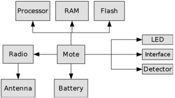
Sensors of the market are generally composed of a core (mote) on which various components are attached (Fig. 1). A sensor is composed of a processor, a memory, a radio, a battery and detectors. [4][17]
Figure 1: General architecture of a wireless sensor
A sensor consists in three elements: an ID card, one or several functions and a communication module (Fig.2). Its ID card consists itself of four elements: a processor, a memory, a battery and an operating system. Communication module consists of a communication mode (for example event communication) client/server communication, and of a communication protocol or a transmission type like WIFI or Bluetooth. Communication module is endowed with a port allowing input/output of messages and events.
Sensor IDCard Func ti on - type Communi cati on P rocessor - manufacturer - type - frequency Batter y - power level Memory - free space OS - name Mode - mode + send() + receive() Protoco l - protocolName - range 1 * 1 1 1 1 1 1 1
For example, the ID card of a Crossbow MICA2 sensor consists of a processor Atmega128 at 4MHz, a 512 KB memory to store the measures, a system memory of 128 KB, a two AA battery and the TinyOS [10] operating system. It communicates in an event oriented way and send messages and events by radio.
A sensor can have several functions by integration of various detectors. It can measure outside temperature, atmospheric pressure, humidity, magnetic field, luminosity, etc. Of course, when it will be integrated into an application, this sensor will play a precise role (see section 5.1.3). This role will use one, some or all the functions of the sensor.
3.2 Messages format
There are several operating systems created for sensors as TinyOS, MantisOS [3], T2, Contiki [7]. Each of them proposes his own messages format. Figure 3 shows the recurrent fields of a sensor message.
This data structure is like a network packet. It defines the address of the destination, the length of the message and the data field. The data field can contain many sorts of data (measurements, video, sound) and also others data structures like commands.
addr length ... data ...
Figure 3: Data structure of a TinyOS message: TOSMsg
4. Presentation of the OSAGAIA model
The OSAGAIA model is mainly dedicated to multimedia applications distributed on the Internet [6]. In this model, components constituting the application are interconnected by data streams. An execution platform supervises their functioning. This platform receives state information from every application component and can send commands to each of them. Besides, it takes care of the application dynamic reorganization by creating/suppressing components and redefining of interconnections between them. To insure the quality of service in such applications which manipulate information with strong temporal dependences supposes to adapt them to user requirements and to environment constraints in real time. OSAGAIA is a model for software components which implements inter-stream synchronization, i.e. synchronization between samples of different streams as for example, sound and image in a video. [6]
4.1 The model
The OSAGAIA model consists in two elements: the Conduit and the Elementary Processor. The Conduit
transports streams synchronously. The Elementary
Processor is a container for Business Components. It takes care to preserve the synchronization between streams and to dialogue with the platform. The Business Component includes the processing of streams. The model accepts two sorts of streams:
- Streams with strong constraints (video, sound, sampled
data)
- Streams with weak constraints (measures on demand,
detectors events).
The used synchronization mechanism consists in attaching a unique time stamp label at every sample at its creation time. The couples sample-label so formed constitute temporal units (TU). To constitute a synchronous sequence of various streams, it is then enough to group together all the Tus corresponding to the same time interval.
4.2 The different components
4.2.1 The Business Component (BC). The BC implements a particular multimedia operation and only one. If, for example, a stream requires an audio acquisition treatment and an audio mixing treatment, it will have to go through an audio acquisition BC and then to an audio mixing BC.
The BC is data driven. It can only run if there are data in the input port of the Elementary Processor (EP) which encapsulates it.
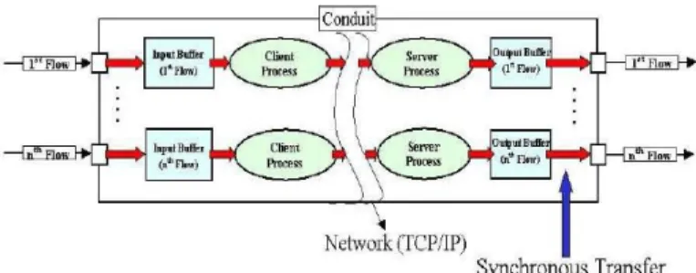
4.2.2 The Conduit. The Conduit transports streams in a synchronous way (Fig. 4). Whatever is the number of streams which it transports, they remain synchronous. Figure 4 describes the path of data within the Conduit. Streams are transferred using a client/server approach. The Conduit has input-output ports to connect to EPs. These ports are connected with buffers which receive the Temporal Units (TUs). Each writing in an output port generates an event used by the EP.
The Conduit has a Control Unit (CU) which allows the platform to know its state at any time and to supervise it.
The CU also ensures that streams are transported locally and by the network in a synchronous way.
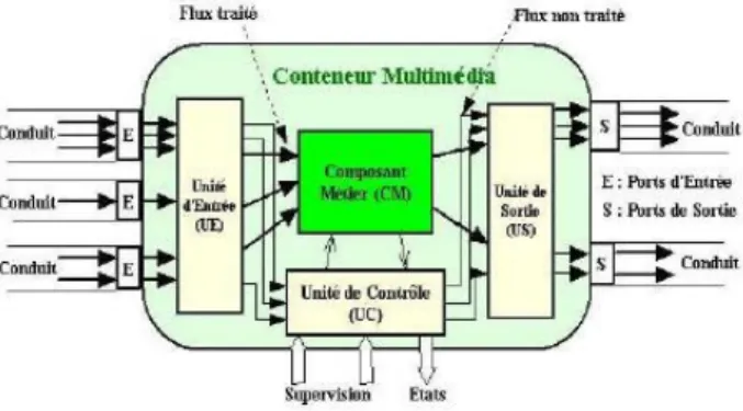
4.2.3 The Elementary Processor (EP). The EP is a container for the BC (Fig.5). Like the Conduit, the EP can be supervised thanks to a Control Unit. The EP also had an Input Unit (IU) and an Output Unit (OU), connected respectively to the input and output ports. The IU and the OU allow the BC to read and write data in the EP input and output ports. They also insure synchronous transfer of streams not handled by the BC.
When the Conduit writes data in its output port, it generates an event which warns the EP that data are present in its input port. The BC can then read the data via the IU, performs its treatment on streams and writes the result in the OU. Writing in the EP output port generates an event which warns the Conduit that it has stream data to transport.
One can find the whole description of the OSAGAIA model in AINA paper [6].
Next paragraph presents what has to be added to sensors to integrate them in this model.
Figure 5: Internal architecture of the Elementary Processor
5. Integration of sensors into the OSAGAIA
model
Whatever the role of sensors is, they produce information flows with hard or soft time constraints. The transport of these flows and their processing using software components services brings us to develop a unique component model able to design such applications based on software and hardware components. Moreover, this model proposes an abstraction of the own nature of each component.
5.1 New functionalities for a sensor
5.1.1 The Control/Input/Output Units. Using the OSAGAIA model, the interconnection of components using their data flows is done thanks to an Input/Output Unit (IU, OU). In addition, the execution platform supervises the Business Component (BC) thanks to a Control Unit (CU) located into the container (the Elementary Processor – EP). In order to inter-connect and to manage the sensor and according to the OSAGAIA model, we add to the sensor a CU, an IU and an OU. The CU allows to send commands to the sensor and to the IU and OU and to get back their state.
This CU is able to communicate with the memory and the battery of the sensor to inform in real-time of the available space for new measures or about the battery level. It can also communicate with the Operating System (OS) in order to supervise the sensor.
5.1.2 The relay function. When an application is modelled with the OSAGAIA model, space is not represented, only the functionalities are. With the aim of integrating sensors in the same way that we integrate software components into an application, it is necessary to ensure that the running platform can supervise each component at any moment and that communication between components is always available. Because a sensor can be mobile, it can be out of reach and induce a faulty running of the application. Nevertheless, if the grid of the network is sufficient, the sensor can be reached provided that there are relays. These relays can be installed by adding a function of relay on the sensors.
The radio of sensors transmits to short way, between 10 and 30 meters (more or less 30/100 feet). On figure 6, a sensor A needs to send a message to a sensor B but the distance is too important between the two sensors. A cannot reach B. The Sensor C located between A and B needs to be a relay. Nevertheless, with a normal execution, when a sensor receives a message which is not designated to itself, it destroys it, that is why we need to add a relay functionality to the sensor in order to allow it to relay a message to another sensor onto the platform. Indeed, in such an application, whatever their location in the network, all the components have to be reachable. This function is essential for the achievement and the supervision of applications in order to make possible to bind all the components.
Adding this functionality allows us to provide a protocol to run the network step by step (hop by hop). It also induces to take into account the sensor limits. The less the sensor has energy, the less it will be able to provide the relay
function. It also may introduce delay and jitter that must be minimized not to disturb the behaviour of the application.
Figure 6: The Relay Function
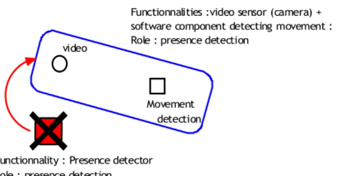
5.1.3. Grouping sensors (notion of role). Let us have an example of presence detection (see Fig.7). An application uses a physical component to detect presence. If this component breaks down, a video sensor located near the detector, associated to a software component of movement detection, can replace it and takes the role of presence detector.
As we can see in this example, a specific role can be achieved by a component alone of by a group of components. We define the role of one or several components as the function into the application insured by the group they constitute [16]. This approach using roles allows ensuring QoS into the application because it offers different ways to obtain a specific role.
video
Movement detection
Functionnality : Presence detector Role : presence detection
Functionnalities :video sensor (camera) + software component detecting movement : Role : presence detection
Figure 7: Notion of role
5.1.4. Model of a EP including a sensor. The addition of these functions induces a new sensor model (see Fig 8.).
As previously defined by the class diagram (Fig. 2), a sensor gets its identity card, its functions and its communication module. Now, we add to it Input and Output Units and a Control Unit in order to communicate with the supervision platform. Input/Output Units provide data flow relay.
Into the OSAGAIA model, the supervision platform is distributed on all sites. Because of memory size and compute power limits it is not possible to locate a part of this platform on each sensor as we do on each computer. That is why we choose to externalize the CU associated to the sensor to the nearest site able to support the platform. The externalisation is not reflected in the UML diagram
Elementary Processor. Actually, the role of the CU is to ensure the link between the component and the platform.
Using this process, the module obtained (Fig. 8) matches the model of the Elementary Processor in the OSAGAIA model. Sensor Communication ID Card Control Unit Function 1 Input Unit Output Unit 1 * 1 1 1 1
Figure 8: Class Diagram of an Elementary Processor
5.2. Software Unified Model
Sensors are able to produce several kinds of data flows. To process the produced information, they communicate with software components able to achieve the specific processing of all information. To integrate sensors among software components, we have to propose a unified component model. This model proposes to integrate a sensor into an Elementary Processor (EP) of the OSAGAIA model. The EP encapsulates the sensor as it would do for a software component. According to OSAGAIA, the Business Component (BC) is used in order to process multimedia flows. A flow enters into the Communication Unit via the Input Unit of the Elementary Processor (EP) and get out through the Output Unit. These units are supervised by the Control Unit of the EP. However, because of the communication mode of sensors, when the EP will integrate a sensor instead of a BC, all information exchange will be done using Input/Output of the Communication Unit (Fig. 9). So, we need to distinguish these flows in order to re-orientate them according to their nature towards the corresponding entity. Sensor Multimedia Container I O E : Input port O : Output port State Flow Commands Flow Flow to relay Data flow IU OU CU Platform Relayed Flow Data Flux States Commands
That is why we use a data flow model including the information of course (data, command) but also an identifier allowing to know if this flow is:
- a data flow; - a state flow;
- a command flow.
The figure 10 shows an application composed of mobile video sensor (V), a mobile sound sensor (S) and a mixing software component (M) located on a non-mobile terminal. On the below part of the schema, a zoom on this non-mobile terminal shows the local part of the platform, the Control Units of the two sensors (V, S) and the Elementary Processor containing the Business Component M. The sensor V sends a video flows to M, but because it is too far, S has to play the role of the relay. S receives this flow, identifies it as a flow to relay and communicates it to its Output Unit in order to transmit it to M. S also sends its own produced flow to M. M reads the two flows received into in Input Unit, identify them as data flows and communicates them to its Business Component. When the platform needs to send a command flow toward V, it sends it to S which relay it to V. This is the same when S and V send state flows to the platform. The relay function allows solving the problem of the mobility of sensors. However, in order to not overload sensors, the platform is distributed on all non-mobile stations; the Control Units of sensors can be moved on another fixed station to be directly reachable to the sensor if possible.
This process allows managing both sensors and software components with a unique way thanks to the generic model.
Now there is a generic model to manage sensors and software components, we have to propose a mechanism facilitating communication between these components. Next paragraph presents such a mechanism.
6. Transformation
Software components usually send and receive data flows whereas sensors send and receive packets whose format is determined by their operating system. In the same way, software components communicate with their UC and the runtime platform with method-calls whereas sensors accept commands using another format (Fig. 3). A network is composed of heterogeneous software components and heterogeneous sensors (different communication protocol and different operating system). We have to set up a mechanism to allow all the elements, whatever their nature, exchanging messages together.
OU IU V S M V : video sensor S : sound sensor
M : mixing software component on a non-mobile terminal
IU OU IU OU IU OU V V S command S command V c o m m a n d V state S st a te V état V CU CU of S CU of V Platform BC V S state S stateV S+V command V command S EP containing M
Figure 10: Example of flows exchanges into an application composed of mobile and non-mobile components
6.1. Data transformation between sensors and
software components
Software components and sensors do not use the same messages format. First use objects, others use packets or events. We have to found a mechanism that acts as a link between such elements.
A first approach consists in introducing a data transformer into the input and output units (IU and OU). First, we can add a data transformer to the OU. When a component wants to send data to another one it has to transform data in the appropriate format. This method implies that the source component must know the type of the destination, which it does not since the application is designed without focusing on the nature of components. If a component has to send information to a sensor and a software component, it should make two sendings, for each destination according to their format. Secondly, we can add a data transformer to the IU. When a component receives a data, it has to identify it in order to transform it in the suitable format. This method implies that the destination component can accept in its entry port any data structure,
but also to know all the data structures of all the components present in the network for carrying out the transformation. In the case of sensors, this method is not applicable due to their small memory. Moreover, each component must know all the possible transformations. When a new transformation is introduce in the application, all components have to be updated what can be difficult to deploy on a real scale.
A second approach consists in using a middleware. [4] describes the characteristics required by a middleware for sensor networks:
- scalable: the application is reduced to essential
components and data types.
- generic: interfaces must be generic to minimize
customization for other applications.
- adaptive: able to change components during runtime.
- reflective: able to change the behaviour of components
instead of changing themselves.
The authors propose a concept of a software-architecture for wireless sensor networks which separates software from hardware and divides the software into three functional blocks (Fig. 11).
Figure 11: Structure of a sensor software [4]
With this architecture, sensors integrate a distributed middleware which is the only way to contact them in order to simplify the development of services for sensor networks. The authors of [8] propose a middleware pattern for sensor networks in order to handle the heterogeneity in sensor applications. It combines services proposed by existing middlewares for sensor networks (see part 2). Services are divided in three categories: Application layer, Data management layer and Network service management layer. They are implemented in separate components in order to make it possible to replace them. Applications indicate their needs to the data management layer which gathers the needed data by sampling the sensors. The same readings are offered to several applications to save sensors energy. The authors mention the usage of standardized interfaces is required in such a middleware.
In our model, we already integrate input and output units in a sensor. Adding a middleware could harm the operation of the sensor due to its low power and its small memory.
Instead of a distributed middleware, we can use a
the data type transformations. Figure 12 shows an application composed of two software components A and B and one sensor C. Instead of sending two messages in two different formats to B and C, A sends its message to the middleware which transforms and sends it to B and C with the appropriate format. However, the use of such a middleware increases networks transfers and add delays because of transaction time with the repository. Our model allows transporting streams synchronously. Is the stream synchronization compatible with the use of a middleware? This question needs to be studied in details.
A
B
C
Middleware Repository
Figure 12: Example of a centralized middleware and its repository
A third approach consists in using software components like in our model. We can define some Elementary Processor of which Business Component would have the conversion processing specific to each type of components (Fig. 13). One component is associated to the conversion component specific to its type. This method limits delay because it only induces some processing time whereas middleware method induces network transfer time. Another advantage is that the synchronization can be preserved. Indeed, the conversion component is a component of our model and consequently contains the properties to keep the synchronization. TC C Platform Useful flow for C Transformed flow Processed flow
Figure 13: Example of conversion component
The disadvantage is that when we reconfigure the application, we have to change the components per pair: the
A fourth approach consists in using the Control Unit (CU) of the Conduit in our model. In the OSAGAIA model, all data streams are transported by Conduits. The Conduit contains synchronization properties that enable to keep the synchronization during the data transport. The purpose is to implement the CU so that it knows all possible data transformations in the network. The Conduit knows the destination and the origin type and recognizes the kind of the flow which it transports. Consequently it can transform data format while transferring them. As the third approach, there is no more network delay, only processing time due to the data transformation.
Obviously, all the methods described in this paragraph require to know all the data types which will be used in the network. They also imply that the application must know the composition of the network constantly in order to recognize the destination type of a message and give it to the appropriate transformation component.
6.2.
Data transformation between sensors and
runtime platform
The platform supervises the components using
commands. However, sensor commands are special structure included in a message packet. The action field value is the action the sensor has to do.
Because the platform knows what kind of sensor it supervises, it can send data in the appropriate format. Then the Control Unit (CU) of the sensor executes commands and transforms the states in the appropriate format.
The name of the method reflects the action field of a command structure. Then the command is integrated in a message packet and sent to the CU of the sensor. The CU uses the inverse mechanism to write the data field value of the response as a state and transmit it to the platform.
7.
Conclusion and perspectives
Sensors become more and more present around us. They have now processing capacities, an important memory and can do measures and capture sound or picture. Our objective is to use them to improve multimedia applications by adding services linked to real world environment.
In order to design such applications easily, we propose a unified component model allowing the developer not to take care of the type (hard/soft) of entities. In this paper, we focused on the OSAGAIA model and show how to extend it to sensors. However, we had to take into account the low capacity and the mobility of sensors. Moreover, we proposed to use Input/Output Units to simply ensure a relay
function in order to avoid the problem of short range of sensors. A prototype implemented with JavaBeans is available and allows simulating the deployment of sensors/software components and their mobility.
This original model allows designing applications using inter-connections of hardware and software components without any particular adaptation of the components involved. The platform is able to supervise these components and can re-organize the circulation of data flows to improve the QoS of the application. It receives states from each of them in order to know how the application runs and sends command to components to drive the execution.
Within sight of the various solutions of data management described in part 2, we can realize that there is a real need with regard to the data transformation and the data management. The majority of the solutions deal with applications specific to sensor networks. Little ones are interested in the problems of integration of the sensors in existing applications. The approach we propose is interested in the problem of components heterogeneity in applications which mix software and hardware components.
Future works will be in the use of the notion of role associated to each component or group of components in order to constitute services and to manage QoS. The re-configuration of the application will be done using the constitution of new services according to the needs of the users, to the available resources to the environment and to the localization of sensors.
As concerns the relay function, we will study how to minimize delay and jitter.
We will also work on data transformation to find an optimal mechanism in term of transfer time, computing time and energy consumption which ensure a sufficient level of quality of service.
References
[1] I.F. Akyildiz, W. Su, Y. Sankarasubramaniam, E. Caryirci, “Wireless Sensor Networks: a survey”, Computer Networks, vol. 38, no. 4, pp. 393–422, April 2002
[2] R. Barr, et al., “On the Need for System-Level Support for Ad hoc and Sensor Networks”, Operating Systems Review, ACM, vol. 36, no. 2, pp. 1-5, April 2002.
[3] Shad Bhatti, James Carlsion, Hui Dai, Jing Deng, Jeff Rose, Anmol Sheth, Brian Shucker, Charles Gruenwald, Adam Torgersonn Richard Han, « MANTIS OS : An Embedded Multithreaded Operating System for Wireless Micro Sensor Platforms », ACMKluwer Mobile Networks & Applications (MONET) Journal, Special Issue on Wireless Sensor Networks, Août 2005.
http://mantis.cs.colorado.edu/index.php/tiki-index.php
[4] J. Blumenthal, M. Handy, F. Golatowski, M. Haase, D. Timmermann, “Wireless Sensor Networks - New Challenges in Software Engineering”, Proc. IEEE Conf. ETFA 03, September 2003, vol. 1, p.p. 551- 556.
[5] P.Bonnet, J. Gehrke, P. Seshadri, “Towards Sensor Database Systems”, Proc. 2nd Int’l Conf. MDM 01, 2001, pp. 314-810. [6] M. Dalmau, P. Roose, E. Bouix, F. Luthon, “A Multimedia
Oriented Component Model”, AINA 2005, The IEEE 19th International Conference on Advanced Information Networkgin et Applications, 28-30 Mars 2005.
[7] Adam Dunkels, Björn Grönvall, Thiermo Voigt, Contiki – a Lightweight and Flexible Operating System for Tiny Networked Sensors. http://www.sics.se/~adam/contiki/ [8] B. Elen, S. Michiels, W. Joosen, P. Verbaeten, “A
Middleware Pattern to Support Complex Sensor Network Applications”, ACM SIGPLAN, OOPSLA '06 Workshop on Building Software for Sensor Networks, 22-26 October 2006. [9] S. Hadim, N. Mohamed, “Middleware: Middleware
Challenges and Approaches for Wireless Sensor Networks”, IEEE Distributed Systems Online, vol 7, March 2006. [10] J. Hill, R. Szewczyk, A. Woo, S. Hollar, D. Culler, K. Pister,
“System Architecture Directions for Network Sensors”, ASPLOS 2000, Cambridge, November 2000.
[11] P. Jacquet, et al., Project Hipercom, INRIA, “Optimized Link State Routing Protocol”, RFC 3626, April 2004.
[12] N. Lee, P. Levis, J. Hill, “Mica High Speed Radio Stack”, 11 Septembre 2002.
[13] P. Levis, D. Culler, “Mate: Tiny Virtual Machine for Sensor Networks”, Proc. 10th Int’l Conf. ASPLOS-X, ACM Press,
2002, pp. 85-95.
[14] S. R. Madden, M. M. Franklin, J. M. Hellerstein, “TinyDB: An Acquisitional Query Processing System for Sensor Networks”, ACM Trans. Database Systems, vol. 30, no. 1, 2005, pp. 122-173.
[15] E. Souto, et al., “A Message-Oriented Middleware for Sensor Networks”, Proc. 2nd Int’l Workshop MPAC 04, ACM Press,
2004, pp. 127-134.
[16] M. S. Voisin Laplace, Conception d'Architectures Logicielles pour intéger la Qualité de Service dans les Applications Multimédias Réparties, PhD Thesis, University of Pau, France, 2006.