HAL Id: in2p3-00802905
http://hal.in2p3.fr/in2p3-00802905
Submitted on 20 Mar 2013
HAL is a multi-disciplinary open access
archive for the deposit and dissemination of
sci-entific research documents, whether they are
pub-lished or not. The documents may come from
teaching and research institutions in France or
abroad, or from public or private research centers.
L’archive ouverte pluridisciplinaire HAL, est
destinée au dépôt et à la diffusion de documents
scientifiques de niveau recherche, publiés ou non,
émanant des établissements d’enseignement et de
recherche français ou étrangers, des laboratoires
publics ou privés.
Preliminary design of the RF systems for the SPIRAL2
LINAC
M. Di Giacomo, B. Ducoudret, J.F. Leyge, J.-F. Denis, M. Desmons, M.
Luong, A. Mosnier
To cite this version:
M. Di Giacomo, B. Ducoudret, J.F. Leyge, J.-F. Denis, M. Desmons, et al.. Preliminary design of the
RF systems for the SPIRAL2 LINAC. 9th European Particle Accelerator Conference (EPAC 2004),
Jul 2004, Lucerne, Switzerland. pp.2017-2019. �in2p3-00802905�
PRELIMINARY DESIGN OF THE RF SYSTEMS FOR
THE SPIRAL 2 LINAC
M. Di Giacomo, B. Ducoudret, J-F. Leyge, GANIL - CEA/IN2P3, France
J-F. Denis, M. Desmons, M. Luong, A. Mosnier, SACM - CEA/Saclay, France
Abstract
In the SPIRAL 2 Linac, a 5 mA, CW, Deuteron beam is accelerated up to 40 MeV, through a normal conducting (NC) RFQ and 26 independent-phase superconducting (SC) quarter wave resonators, working at 88.05 MHz. Tube and solid state amplifiers derived from the standard FM transmitter modules are foreseen while a new digital control system is being designed for the feed-back and feed-forward amplitude and phase control..
The paper presents the power and low level systems for both the NC and SC cavities and results of simulations of the RF system in operating conditions.
INTRODUCTION
SPIRAL 2 [1] is the new GANIL project for a second generation RIB facility . The driver accelerator has to be operated for over 6000 hours/year and to handle a 200 kW ion beam with up to 14 kW CW beam loading per cavity.
High reliability and ease of maintenance are then the strongest design criteria leading to the choice of the solid state technology for power amplifiers, and digital solutions for the low level RF control electronics.
POWER AMPLIFIERS
SC Cavities
The power required by the SC cavities is mainly dominated by the beam loading, which can change by a factor five between the deuteron beam (5mA) and a future ion beam (1mA, q/A = 1/3). The beam loading of each cavity is optimised for the deuteron beam dynamics. It ranges from 1 to 13 kW as shown in figure 1.
Figure 1: Beam loading of the different cavities The corresponding RF power depends on the cavity tuning, which is mainly affected by two factors: the reactive beam loading due to the synchronous phase, and the mechanical vibrations.
The first one can be compensated by a fixed cavity detuning of opposite sign (detuning compensation). The
second one has to be controlled by a fast tuning system or limited by a good cavity stiffness and helium pressure stability, otherwise the RF efficiency decreases dramatically.
Figure 2 : RF Power distribution along the Linac Figure 2 shows the result of a computation assuming a maximal acceptable mechanical detuning, fixed coupling (Qext = 6.6 105 for low-β cavities and Qext= 1.14 106 for
high-β cavities) and detuning compensation. Losses and mismatches in the RF transmission lines require an extra power of about 10% while 5% additional budget is taken into account for the amplitude and phase regulation. In the low-beta section, the maximum allowed cavity detuning is 65 Hz with 10kW RF amplifiers. This detuning is reduced to 55 Hz in the high-beta section, with 20kW RF amplifiers. The RF efficiency (beam power to RF amplifier power ratio) is 84% with perfect reactive compensation and 64% with 55 Hz static cavity detuning. The figure also shows the amount of reflected power to be handled by the circulators or isolators.
In order to reduce the investment cost, it is important to optimise the installed power, trying to fit the amplifier power curve as better as possible. This criterion will also reduce the running costs as the efficiency of the RF amplifiers always decreases when they work far from the maximum power they can deliver.
In the 10 to 20 kW power range, both solid state and vacuum tube amplifiers are available. Their cost is quite the same up to several kilowatts, while at higher power the cost ratio between the two technologies increases and favours tube amplifiers over the other. Taking into account the isolator cost, the crossing point between the two technologies can be situated around 10 kW today. Nevertheless the market is changing very quickly and, only during the last 4 years, the maximum power commercially available in the FM range of frequency has grown from 3 to 30 kW. Several reasons justify this trend : the high cost of the tube which is strongly dependent on the manufacturing process, the much longer life time of Proceedings of EPAC 2004, Lucerne, Switzerland
transistors, the security aspects related to the absence of very high bias voltages and their modular structure which allows an easy and fast trouble-shouting in case of failure.
0 5 10 15 20 25 30 35 1999 2000 2001 2002 2003 2004 2005 Year s
Figure 3: Recent growth of the available power in solid state technology at 88 MHz.
Solid state devices developed for industrial FM emitters are based on power transistor (planar and vertical MosFET) modules with a 50 V power supply. They deliver 300 to 350 W and are assembled in units with 1 to 2 kW capability each.
Figure 4: Example of 1 and 2 kW standard FM units. (Courtesy of R&S and ECRESO)
To obtain higher power levels, these modules are then combined by coupling devices as shown in figure 5.
Figure 5: 88 MHz solid state amplifier structure A control unit monitors all the RF and DC main parameters and localises the possible hardware failure. This organisation leads to a very friendly maintenance procedure as each failure can be recovered in a few minutes by replacing the faulty unit, the control unit information being available in local and remote modes by a simple network link. Combiners to obtain up to 30 kW have been developed during the very recent years, then the very different device to be installed in the chain is the isolator to absorb the reflected power. Unlike the FM
broadcast applications, SC cavities have to be operated frequently with a high voltage standing-wave ratio (VSWR).
The circulator and the dummy load can be put after the amplifier, distributed at the single unit or at each 300 W module. The first solution is more expensive and bulkier but more reliable with regard to the combiner and the feeder. The last one supposes a new design of the printed circuit but should protect the single transistor amplifier more reliably. Intermediate power prototypes of the two distributed solutions are foreseen.
Air-cooled FM amplifiers offer a lifetime of about 20 years. The transformation to water-cooling (much longer life time) charges at least 20% of extra costs. Therefore, a detailed analysis of the amount of power that can be correctly evacuated from the technical gallery by ventilation is being carried out to decide the cooling method.
RFQ
The RFQ cavity requires around 150 kW with a beam loading of few kW for ion operation voltages, or some 70 kW for deuteron operation with a beam loading of less than 10 kW. A total power of 180 to 200 kW has then to be available at the amplifier.
Several possibilities exist to couple the cavity to the amplifier, each one has different advantages and drawbacks.
Figure 6: RFQ driving possibilities
Using a single coupler seems to be the less expensive solution since only one vacuum window and one power amplifier are required. Nevertheless the solution requires a non standard amplifier, concentrates on the coupler all the failure risks and asks for a large aperture on the cavity structure. Using several couplers requires a higher power budget, as the impedance matching at several ports is more complicated, but reduces drastically the coupler complexity and the field asymmetries. Splitting the power of one single amplifier requires expensive power splitters while using different amplifiers requires big ferrite circulators to eliminate coupling between the amplifiers and risk of oscillations. The last solution is very attractive as the output power of each amplifier is not far from Proceedings of EPAC 2004, Lucerne, Switzerland
standard 30 kW FM transmitters. Then, more possible manufacturers exist and the investment cost could be significantly reduced. Maintenance cost would be reduced as well, as the spares for the 4 amplifiers would be less expensive. Considering the progression of the available power in the solid stage technology, the 4 amplifiers could be solid state in few years.
LLRF SYSTEM
Considering that a low level radiofrequency (LLRF) system is required for different types of accelerating structures (normal-conducting RFQ and bunchers, super-conducting QWR) fed by vacuum-tube amplifiers or solid state amplifiers, the flexibility offered by digital techniques makes them ideal candidates for the implementation of the LLRF systems in SPIRAL2. A common hardware design where all the key functions are integrated in a high performance programmable logic chip (FPGA) could fulfil the specific requirements of the different combinations. Furthermore, such a digital implementation with a high level of integration provides a better performance in terms of noise and reliability at a lower cost for manufacturing and maintenance.
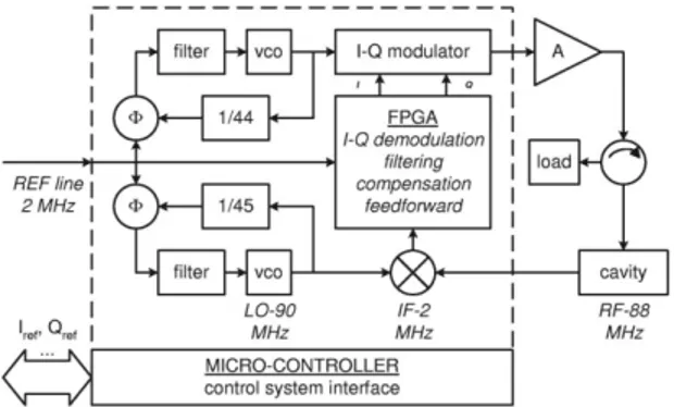
Figure 7 : LLRF system for SPIRAL 2
A sketch of the design is given in figure 7. The reference signal (2 MHz) is conveyed by a coaxial cable with an excellent phase stability while sampling this signal simultaneously with the IF signal realizes a 4-quadrants I-Q demodulation. The dynamic compensation of the feedback loops is implemented as an IIR filter in the same FPGA. A feed-forward functionality is also available through the FPGA or micro-controller. The latter provides a straightforward interface with the accelerator control system without expensive VME ADC-DAC boards. The reference signal distribution could consist in an ultra stable Cesium frequency standard followed by industrial low phase noise RF distribution modules. Flexible phase stable cables (200 PPM variation in the range of 10 to 40 °C) would carry the reference signal from the distribution module to each LLRF unit.
The performances of the amplitude-phase or I-Q regulation have been simulated with a Matlab/Simulink code and the PSTAB code [2]. Perturbations for the SC QWR cavities operation consist mainly in mechanical vibrations (microphonics) and beam gaps created by the
slow chopper necessary in the commissioning stage, while Lorentz forces detuning is negligible. For the analysis, microphonics are modelled by a 40 Hz sine modulation of the QWR resonant frequency. This frequency corresponds to a mechanical resonance. However, only measurement on a QWR prototype could provide the amplitude of the modulation. By default, an amplitude of 50 Hz, compatible to the assumption used for the power distribution calculation, is considered. A conservative choice has been made for the feedback loops parameters, i.e. gains of 100 and delay of 5 µs. Figure 8 shows the amplitude and phase stability at the last QWR with (red curve) and w/o feedforward (blue curve).
Figuer 8: Amplitude and phase at the last QWR
Relative amplitude stability with beam (outside the gap) ranges about 5 10-5. Because of the unpredictable phase of microphonics, a feedforward does not necessary improve the regulation but could require a higher power budget. Accounting for the cumulative errors along the linac, the performances reduce to 10-4 and 0.7°, respectively for the amplitude and phase stability. The energy and phase deviation along the linac are displayed on Figure 9. When the chopper switches on, a short transient about 50 µs could lead to a larger deviation, 3° in phase and more than 50 keV in energy at the end of the linac.
Figure 9 : Energy and phase deviation along the linac
AKNOWLEDGEMENTS
Several people and companies helped us with information and quotations on different items. Among them, we would specially thank Ti Ruan from the SOLEIL group, A. Facco from INFN/LNS, the teams of dB Elettronica, Ecreso, R&S, Thales BM and TED.
REFERENCES
[1] A. Mosnier, Proceedings of Part. Acc. Conf. 20O3, Portland, P195.
[2] A. Mosnier, Proceedings. of Int. Linac 2000, Monterey, P. 815.
Proceedings of EPAC 2004, Lucerne, Switzerland