HAL Id: hal-01900762
https://hal.archives-ouvertes.fr/hal-01900762
Submitted on 22 Oct 2018HAL is a multi-disciplinary open access archive for the deposit and dissemination of sci-entific research documents, whether they are pub-lished or not. The documents may come from teaching and research institutions in France or abroad, or from public or private research centers.
L’archive ouverte pluridisciplinaire HAL, est destinée au dépôt et à la diffusion de documents scientifiques de niveau recherche, publiés ou non, émanant des établissements d’enseignement et de recherche français ou étrangers, des laboratoires publics ou privés.
Dedicated Object-Processor for Mobile Augmented
Reality-Sailor Assistance Case Study
Jean-Philippe Diguet, Neil Bergman, J-C. Morgère
To cite this version:
Jean-Philippe Diguet, Neil Bergman, J-C. Morgère. Dedicated Object-Processor for Mobile Augmented Reality-Sailor Assistance Case Study. EURASIP Journal on Embedded Systems, SpringerOpen, 2015, 2015 (1), �10.1186/s13639-014-0019-6�. �hal-01900762�
Dedicated Object-Processor for Mobile Augmented Reality
Sailor Assistance Case Study
-Jean-Philippe Diguet(1,2), Neil Bergman (2), J-C. Morg`ere (1)
(1) Lab-STICC, CNRS - UBS, Lorient, France, (2) University of Queensland, Brisbane, Australia October 22, 2018
Abstract
This paper addresses the design of embedded systems for outdoor augmented reality (AR) applications integrated to see-through glasses. The set of tasks includes object positioning, graphic computation as well as wireless communications and we consider constraints such as real-time, low power and low footprint. We introduce an original sailor assistance application, as a typical, useful and complex outdoor AR application, where context-dependent virtual objects must be placed in the user field of view according to head motions and ambient information. Our study demonstrates that it is worth working on power optimization, since the embedded system based on a standard GPP+GPU consumes more than high-luminosity see-through glasses. This work presents then three main contributions, the first one is the choice and combinations of position and attitude algorithms that fit with the application context. The second one is the architecture of the embedded system, where is introduced a fast and simple Object Processor (OP) optimized for the domain of mobile AR. Finally the OP implements a new pixel rendering method (IPS), which is implemented in hardware and takes full advantage of Open-GL ES light model. A GP+OP(s) complete architecture is described and prototyped on FPGA. It includes hardware/software partitioning based on the analysis of application requirements and ergonomics.
1
Introduction
Recent breakthroughs in Augmented Reality (AR) display will bring a lot of new applications in the future. However, this also means an emerging challenge, which is the design of cost, low footprint and low-power systems to be embedded in see-through glasses. On the one hand, most of research works in related conferences (e.g. ISMAR), don’t focus on embedded system design but on specific AR issues such as simultaneous localisation and mapping or virtual object handling. On the other hand emerging see-through glasses are considered as a new peripheral connected to smartphones, which can execute AR applications. The contributions of this work are twofold. The first one is an in-depth study of algorithms for the target AR application in the domain of sailor assistance. The second one is the design of an architecture that fits with application requirements. The application domain is outdoor AR without any equipment in the user environment. Such applications require the management and the fusion, at runtime, of multiple information flows (position/attitude sensors, points of interest, ...) and simultaneously the processing of graphical objects. The paper is organized as follows. In section 2 we present our motivations for this research field and the specificities of the target applications. In section 3, we present current technologies for AR and a state of the art of usual implementations. Section 5 describes the main steps of our original approach. Our solution is based on the adaptation of previous positioning solutions to the application context, on algorithmic transformations to improve data reuse and reduce processing load, and on a new architectural solution for object drawing. Section 6 presents our hardware/software architecture based on data-locality and bandwidth optimization. Our architecture is dedicated but flexible and optimized according to AR applications; we come up with a coprocessor-based solution that provide a possible IP for mass market products. In section 7, we present our prototyping results on FPGA and discuss performances estimations. Finally we conclude and draw some overall insights.
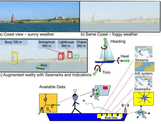
a) Coast view – sunny weather Buoy 700 m Semaphore 800 m Chapel 950 m Lighthouse 900 m Heel Trim Heading 3m/s
b) Same Coast – foggy weather
c) Augmented reality with Seamarks and Indications
GPS So Su Sb Boat Data Available Data AIS system Seamarks Streams
Figure 1: Sailor Assistance AR case study.
2
Outdoor AR applications: case of sailor assistance
AR by itself is not a new topic but many challenges remain unsolved. This is especially true in mobile and outdoor contexts, where field markers are not applicable and video-assisted model-based tracking are difficult to implement in real-life luminosity conditions. The proposed application set is based on the following observations. First, designers already have at their disposal a huge amount of recorded and classified data of geolocalization. Secondly, these data can be added to a user’s field of vision by means of see-though glasses. Third, an embedded system can compute 3D objects that fit with the landscape, if appropriate sensors can provide the user attitude. Fourth, we consider an application based distant objects that don’t require an extremely accurate positioning, so no camera is needed for the pose estimation. Finally basic ergonomics rules for positioning applications, require simple and meaningful objects in the user field of view. In this context many applications, in civilian and military domains, can be designed to improve security and navigation decisions with different hands-free and low footprint devices. In this context, we consider the particular but complicated case study of sailor assistance from which can be derived various requirements for a generic embedded system. This case study is illustrated in Fig.1.
On a boat, the understanding of the position is vital when approaching sensitive environments such as coasts, open sea reefs, high-density navigation zones or harbor channels. These situations are true for small sailing or motorboats but also on large vessels where the navigation crew is limited with respect to boat sizes. In this kind of large ships, it is also recommended to combine visual checking, based on real environment observations, and instrument piloting. Current methods consist of going back and forth between map analysis and visual observations. However matching map indications with a real environment can be tricky and error-prone. It also represents a loss of time that can be precious in case of emergency. Finally, this matching can be simply impossible when the visibility is very bad This is a relevant case study since a ship is a very unstable system. All the continuing motions have various parameters depending on boat speed, user moves and ocean oscillations. Swell periods can vary between 0.05Hz and 0.1Hz. However this is also a domain where a lot of data are available. The first category includes static seamarks objects. The second one is dynamic but can be estimated, in this category we find for instance the ocean streams and the tide-dependent shallow areas. The third one is provided by the Automatic Identification System (AIS) that broadcasts the positions, the heading and the ID of boats or any maritime objects in the surroundings.
All these data can be added to the user fields of vision according to position and attitude estimations. Then we have boat-positioning data, which include GPS measurements, speed, trim, heel, and heading. All these data, which can be encrypted in sensitive or military applications, can be obtained through a wireless network that doesn’t require high bandwidth capacities. However these data are useful but not sufficient since it is necessary to know the user attitude, which is defined with the head angular positions. These data have to be provided by embedded sensors that must be integral with the glasses. Redundancy between boat and user data can also be usefully combined to improve accuracy. For instance the on-glasses accelerometers can be combined with the ship GPS to estimate local moves on a long vessel.
The intensity of the see-through device is also an important constraint in such outdoor applications. It must be compliant with the weather conditions such as rain, fog or intense light reflection in sunny conditions, moreover the system must also be usable at night.
Finally, ergonomics are of the greatest importance in navigation applications where the objective is to provide the user with useful and relevant information. Feedbacks from potential users we are working with, in both civilian and military domains, confirm that the number of objects must be limited and that object forms must be simple. These requirements let us consider that a graphics processing unit (GPU) is actually not necessary, it also means opportunities for implementation optimizations.
3
State of the art
Recent technology breakthroughs are enabling new kinds of applications, hereafter we discuss this evolution in three parts: display, applications and embedded systems.
3.1 AR Technologies
The first breakthrough occurred in the domain of sensors for position, speed, acceleration and attitude (yaw, pitch, roll) measurements. For a long time, the size, and cost of such devices have limited their use to navigation instruments in aircrafts and satellites. However MEMS technologies are now providing integrated and low cost Inertial Measurement Unit (IMU) solutions [13, 19] that make possible the design of mobile consumer systems. The most widespread solution is based on the association of two kinds of MEMS devices: a 3-axis accelerometer sensor and a 3-axis magnetometer sensor. The combination of these sensors can provide the estimation of body translations and attitude, it means 3 axis inclinations and so compass capabilities. ST has introduced in 2010 a new single module solution integrating these two kinds of MEMS sensors, with significant improvements in terms of accuracy and linearity. More recently gyroscopes, that return angular velocities, have also been proposed in integrated versions. Invensense has unveiled in 2010 an IMU including a 3-axis integrated gyroscope (angular speed) combined with a 3-axis accelerometer. In 2011 ST presented the iNemo engine that includes 3-axis linear accelerometers, 3-axis angular speed measures, a magnetometer (heading) and a barometer (altitude). Like the Invensense solution, the whole device uses a 32 bit processor to filter motion sensor data but the access to this processor is very limited. Moreover integrated gyroscopes consume one order of magnitude more power than magnetometers and accelerometer. We present solutions to these issues in section 5, we show that gyroscopes are not needed in our context and that a simple softcore processor synthesized on a FPGA can run motion estimation algorithms. The second key technology that opens new horizons to AR applications comes from the domain of head mounted displays (HMD). New see-through glasses (see Fig. 2), are now affordable. Companies like Vuzix, Optinvent, Laster or Lumus have developed prototypes or already commercialized some products with some limitations. The arrival of Google on this market will also boost AR-related applications. In [17] the authors present an interesting overview that compares the different optic technologies and patents. This type of device paves the way to future AR reality applications on a mass market. Moreover in 2011, the first prototype of a single-pixel lens has been demonstrated [14]. However one of the main issues in our context is the need of high luminosity, Laster proposes a mask with a very important intensity based on a backlight LCD, it offers 5000 cd/m2 whereas usual OLED-based solutions provide intensity around 200-400 cd/m2.
Optical See-Through HMD Pico Projector Computer Virtual 3D objects Real World Optical Combiner / Element
Lumus Laster Optinvent
Vuzix
Figure 2: See-through glasses.
3.2 Outdoor applications
In our outdoor context, efficient markers-based solutions [8] can’t obviously be used. Relevant markerless solutions based on image processing [3, 9] could be proposed instead, the solution described in [24] is for instance promising on mobile platforms. However it is not applicable in our outdoor conditions and other issues such as the important distance of targets and boat motions disqualify this approach. For outdoor positioning and orientation, some solutions based on data have been introduced but are first based on handled devices (e.g. Android and iOS) and secondly are not accurate enough to place an object at the right place. A solution, based on a differential GPS was proposed in [4] with inclinometer and magnetometer to display text information on campus buildings. The authors noticed the acceptable inaccuracy with regards to the application requirements, but they also indicated issues with visibility in sunny conditions and difficulties with the inertial sensors. Sensors and related signal processing have been improved since, but visibility and integration still need to be solved.
3.3 Embedded system architectures
Miniaturization and power consumption are the first constraints for the design self-content mobile AR sys-tems. Object positioning and drawing require computation resources but control capacities are also necessary to handle data acquisition from sensors and communication protocols. The implementation of the first pro-totypes for such applications, were based on backpacked laptops with 3D graphics cards [4, 15]. Advanced mobile multiprocessor architectures are now available (e.g. OMAP5, Snapdragon, Atom N2800, ST-Ericsson Nova, Apple A5, ...), they are typically based on cortex ARM cores or Intel Atoms with specialized Graphics and Video coprocessors. The main advantage of such architectures is the availability of software develop-ment frameworks. This kind of platforms are typically embedded in recent AR systems that also integrate IMU sensors: OMAP3530 for Optinvent and OMAP4430 for Vuzix and Google. However they are mainly used to handle the video stream and the wired or wireless communication with a smartphone that remotely runs the AR application. As a matter of fact, high-resolution video games, video and image processing for object identification and complex online 3D graphics computations would justify such processing resources. However the type of AR applications we are targeting, require simple objects instead. Secondly they do not need cameras and complex pose computation that requires image processing. So we believe and we demon-strate that such General Purpose Processor (GPP)+GPU solutions are actually oversized regarding power autonomy constraints. We present in 4 an implementation of such a solution based on the Nova SoC. An-other possible solution is provided by reconfigurable architectures that enable specifically optimized and low frequency designs. These rely on Hardware / Software design methodologies and recent high-performance FPGAs. These FPGAs are often power-hungry however the roadmap of FPGAs is clearly focused on this power issue with the aim to address the embedded system market. Recent hybrid ARM/FPGA architectures such a Xilinx/Zynq open new perspectives. On-chip memory capacity is also a key issue where significant
progress have been made. For example, the Artix Xilinx low power, low cost family embeds up to 12Mbits of block RAMs. Regarding GPUs on FPGAs, Xylon has added a 3D graphics module to the Logibrick library available under license in an early access version for evaluation. The architecture relies on a 3 stage pipeline. This solution is a simplified version of the usual graphics pipeline and is designed for general purpose Open-GL-ES applications. It shows that low frequency dedicated architectures can be designed for this purpose. In [11] the authors present a GPU-inspired and multi-threaded softcore architecture, which is programmable with the NVIDIA Cg language. The aim is to simplify the use of FPGA-based acceleration boards for High Performance Computing. Our approach is different, it is dedicated and designed for embedded systems and AR applications with a high focus on data locality optimization for minimizing data transfers.
4
Mobile-platform based standard Implementation
We have designed an AR system based on standard platform and software, to evaluate the impact of the embedded system compared to the AR display device.
4.1 AR Display
As presented in section 2, our class of applications require optical see-through displays 2. Considering weather conditions (light reflection, fog, humidity), it turned out that Laster was providing the better solution for our outdoor conditions. The maximum light intensity of the product (ski mask) is about 5000 candela/m2 in color mode and monochrome is even higher. The resolution and the field of view are suitable for a see-through device: 800x600 and 40*30 degrees respectively, which is better for light intensity (x10) and field of view (x2) than other solutions. The display technology is based on a LCD panel with LED backlight to reach expected high luminosity that cannot yet be delivered with AMOLED technologies.
4.2 SoC and development board
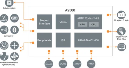
We have implemented a first version of the application on a ST-Ericsson Snowball board, which includes the A9500 SoC (see Fig.3). It is a GPP+GPU architecture that implements a double cortex A9 with a flexible clock frequency between 200MHz and 1.0GHz and a GPU Mali-400 MP. It also includes a wireless communication chip that provides Bluetooth (BT), WiFi and GPS. Head tracking can be performed with the MEMs available on the board, which are an accelerometer / magnetometer 3 axis (LSM303DLHC from ST) and a gyroscope 3 axis (L3G4200D from ST). The GPS data are supposed to be available from the boat or user throughout the low-bandwidth wireless (BT) connexion, so the GPS and the WIFI are switched off.
Table 1: Power measurements: Snowball 1GHz (SB), Laster AR Mask, Andro¨ıd (OS), BT ( 7Kb/10s), No background, Simple Objects.
Power mA
MASK SB SB SB, OS SB, OS SB, OS
uboot OS BT BT, EKF BT, EKF
MEMS MEMS Objects [100-130] 310 350 460 470 500 Voltage (V) / Power (W) 7,2/[0,72-0,94] 5/1,55 5/1,75 5/2,30 5/2,35 5/2,5 4.3 OS and Software
The Mobile OS is Android, it offers a large amount of APIs that simplify GPU programming with openGL ES 2.0 API [18], allows to control and acquire MEMs data (sensorManager) to get position data from a GPS (LocationListener) and some managers to handle wireless connectivity (BT, WiFi). As a proof of portability, we have also implemented the application on a Galaxy S3 smartphone, which is based on the same GPU. In AR applications the main functionality is the graphic service, the system has to draw 2D or 3D objects with different colors and textures. The second service is the attitude computation or head tracking, this step is needed to place right objects in right orientation on the display. A special task with MEMs is implemented, it is mainly based on a standard 7-states Extended Kalman Filter [16], we come back on this type of filter in section 5. The MEMs data rate is set to 50Hz. Finally a wireless service was developed to acquire data from the boat network (GPS, AIS, map sea-marks, wind and stream grids) when those data are available from a PC on the boat. We used the NMEA protocol commonly used in marine electronics and BT for wireless communications, that don’t require high bandwidth.
4.4 Power measurements
We measured the power consumption of the Snowball board and the Laster mask with different configura-tions, the results are given in Table 1. The mask has five levels of luminosity and the highest one consumes 130mA. We then observe that the power consumption of the embedded system is much larger than the AR display, it consumes 310mA with a basic kernel and reaches 500mA with Android, BT, MEMS (without Gyroscope) and the application running with a set of simple objects. Expressed in Watts, the SB board consumed 2.5 times more power than the Mask with the highest luminosity. We note that the Bluetooth con-nexion (version 2.1-EDR) significantly increases the power consumption (110mA), in practice this overhead can be drastically reduced with a low-power version (e.g. 4.0).
4.5 Conclusion and optimization opportunities
We can draw the following conclusions from this experiment. First, contrary to common beliefs the power consumption of the embedded system is dominant even if a high intensity AR LCD display is used. It means that the embedded system represents real opportunities for power optimizations. From a general point of view, 3D graphics represent complex and greedy tasks but optimizations and simplifications are possible if we consider ergonomics constraints and requirements of the most promising AR outdoor applications with see-through glasses. Considering the application context (orientation and notifications), we can point out three of them. First, object distance means that we can relax the accuracy constraint since the size of the objects is decreasing with distance. Secondly there is no background and a limited number of simple objects, the background is the real world and ergonomics impose that a few simple objects can be drawn at the same time. Finally, useful orientation objects are static or move slowly if they are far away. All the previous features provide a rationale for a simplified implementation of 3D graphics that may be usefully exploited to optimize and specialize the design of the embedded system. Our solution follows this approach and is demonstrated on FPGA devices.
5
Application: algorithm and optimizations
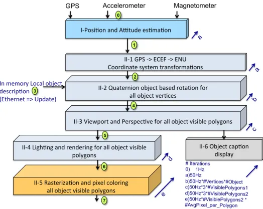
In the following sections we present the design choices to specify and implement the application flow described in Fig.4. We address the three following points: i) Object positioning according to sensors and application context, ii) Object drawing, iii) some optimizations that have been introduced according to the application context.
5.1 User attitude modeling
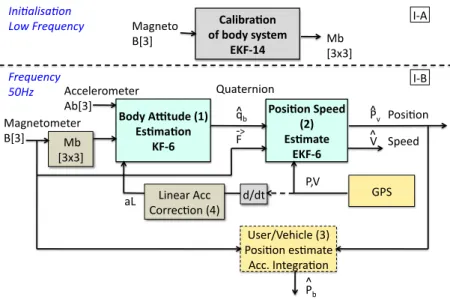
The aim of stage I in Fig.4 is to compute user orientation and position. Our objective was to develop a robust and gyro-free solution based on magnetometer, GPS and accelerometer. The choice of a gyro-free solution is motivated by the cost, the footprint and the power consumption, which is one-order of magnitude larger compared to magnetometers and accelerometers. There were two difficulties. The first one was the state of the art that was mainly related to aircraft, automotive systems or AR applications with computer-based implementation without great concerns about size and power consumption issues [23]. The second point is related to the filtering and estimation problem, actually determining position, speed and attitude from a set of noisy sensors is a non-linear problem that can’t be solved with traditional Kalman filters. We’ve studied various kinds of alternative solutions for non-linear filters, which were based on EKF (extended Kalman filter) [10], UKF (unscented Kalman filter) [20] or UPF (unscented particle filter) [12]. According to the current project environment and constraints, it turned out that applying Wahba’s method can solve the question of the gyroscope. This technique has been applied in aeronautics and avionics domain in [6] and considers gravity and magnetic field as the two required non-collinear vectors. It is based on the quaternion modeling, that also offers interesting properties such as the computation complexity for rotations, the stability in presence of coding and rounding errors and the inherent robustness regarding the gimbal lock problem. Our complete solution for position and attitude estimation is described in Fig.5. It is finally is based on a low complexity 6-states EKF (I-B(2)) algorithm for speed and position estimations. This EKF is loosely coupled with a low frequency GPS and gets the body attitude data, as a quaternion vector, from a 6-states KF algorithm that implements Wahba’s method (I-B(1)) and used a Linear Acceleration derived from the GPS speed (I-B(4)). The proposed EKF-6 algorithm was previously applied in [1] with gyroscope data that are removed in the proposed version. Moreover the acceleration data are combined with data from GPS after filtering. The complete solution also relies on a robust method for the auto calibration of the magnetometer [7]. It leads to a complex 14 states EKF algorithm (I-A) , however it is used only once at start time or with a very low frequency if the environment is changing. Note that the solution can easily be augmented with new data. It means that if gyroscope data are available with reasonable cost and footprint, they can be added to the model.
5.2 Virtual Object: Geometry Stage
The objective is to select only objects of interest in the context of the user. The definition of interest is a real question we study with different categories of users, but it is out of the scope of this paper. In this work we consider three configurable parameters but various rules could be introduced as well. The first one is obvious; this is the position in the user field of view. The second is the minimum size of object after 2D projection. The third one is the choice of accessible objects stored in the object memory. This selection is implemented in software and can be configured according to confidentiality issues or contextual search criterions. Hereafter, we summarize the steps of the geometry stage.
From GPS to ENU Coordinates Given the GPS coordinates, two successive transformations are applied to position and orientation data (stage II-1). The first one is the step from GPS to ECEF (Earth-Centered, Earth-Fixed) and then from ECEF to ENU (East North Up).
Object Rotation based on User Attitude The user attitude, namely the three angles that define user head orientation, is modeled with the quaternion formalism (q = q0 + q1.i + q2.j + q3.k). Then a rotation (from V to V0) is applied in stage II-2 to every point of every visible object according to the
I"Posi'on)and)A-tude)es'ma'on) GPS Accelerometer Magnetometer In)memory)Local)object) descrip'on)) (Ethernet)=>)Update)) II"1)GPS)">)ECEF)">)ENU) Coordinate)system)transforma'ons) II"2)Quaternion)object)based)rota'on)for)) all)object)ver'ces) II"4)Ligh'ng)and)rendering)for)all)object)visible) polygons) II"3)Viewport)and)Perspec've)for)all)object)visible)polygons) II"5)Rasteriza'on)and)pixel)coloring)) all)object)visible)polygons) II"6)Object)cap'on) display) # Iterations 0) 1Hz a) 50Hz b) 50Hz*#Vertices*#Object c) 50Hz*3*#VisiblePolygons1 d) 50Hz*3*#VisiblePolygons2 e) 50Hz*#VisiblePolygons2 * #AvgPixel_per_Polygon e a a b c d 1 2 3 4 5 6 0 7
Figure 4: Global application flow
following operation:
V0 = qV q−1 where q−1 = q0− q1i − q2j − q3k (1)
In-viewing Frustum Test, 3D→2D The objective of the 2D projection step is firstly the selection of visible points and objects within the user field of vision and secondly the computation of 2D coordinates after a perspective projection. An object is considered as visible if it is in the field of vision, which is defined with horizontal and vertical angles. It must also have a size bigger than a minimum sphere, which is defined by a ray R. The viewport operation is based on these bounding values and requires, for every point of all relevant objects, 4 multiplications and 4 tests. Then the projection can be computed with 3 divisions per object and then 4 products for every point of all visible objects.
5.3 Virtual Object Drawing
Three Visibility Tests The two first tests are applied in stage II-3 before drawing any object. The first one has been described in the previous section. The second test addresses the sign of polygon normal vectors. Considering opaque surfaces, if the Y’ value Ny of the polygon normal vector in the user coordinates system is negative, then the polygon isn’t visible. Based on vertices’ coordinates, this value is computed for each polygon and requires 3 multiplications and 4 additions. The third test is the well-known Z-buffer test (Y-buffer with our conventions) in implemented. The aim is to avoid drawing polygons, which are hidden by some closer ones. It is based on an array A[i,j] that stores the smaller Y value of the closer polygon point located at the address (i,j), where i and j correspond to the ith line and jth column of the display. We have implemented this test in stage II-5 with a dedicated module that computes the address and performs the comparison and update, details are given in Section 7.
Light modeling and Optimization Models used in stage II-4 are based on the barycenter method from OpenGL-ES. The light model for each Vertex of the triangle polygon is given in Fig.7. Once the three vertex lights are computed (L1, L2, L3), the barycenter method can be applied to fill the triangle A,B,C and compute each vertex light as follows:
!"#$%&"'()* (+*%(,-*.-./01** 234567* !"#$%&'(( )*+,( !-*+.+,( !"#$%&#'%$(") *(+),-./0."12) ,-./0."12) 3456) /01( /0)( 8(,-*9:/;,0*<6=* 2.'1"'()** 345>* ?(.$'()*@A00,* <B=** 2.'1"/0** 2345>* 122%3%4'5%&%4( 1-*+,( (!-*+.+,( 67"&%4$8'$( 9-( :( ;( 0<( =>( :( ='?8@'$( A( :( BC%%D( E=B(( F?%4GA%H823%(I+J( ='?8@'$(%?@5"&%( 122K(/$&%#4"@'$( =LA( DGD&( "M( M8$%"4(122( N'44%2@'$(IOJ( !"#$%&'5%&%4( )*+,( =-( :(
Figure 5: Position and attitude estimation
x’ z’ RZmax RXmax x o o z’ y’ A(3D) A’: perspective projection of A View Plan x’ A’(2D)
User coordinates [x’,y’,z’] 2D projection
Figure 6: From user 3D coordinates to 2D view plan
where: c = R, G, B, A(x, z) = F23(x,z) F23(x1,z1), B(x, z) = F31(x,z) F31(x2,z2), C(x, z) = F12(x,z) F12(x3,z3) and Fij(x, z) = (zi− zj)x + (xj − xi)z + xi.zj− xjzi.
The implementation of this method has been optimized as follows: Fij can be computed only once for each triangle and Kpx(c) and Kpz(c) can be defined as unique color increments on X and Z axis respectively:
- Kpx(c) = LF1(c)((z23(x12,z−z1))3)+LF2(c)((z31(x23,z−z2))1) +LF3(c)((z12(x31,z−z3))2)
- Kpz(c) = L1F(c)((x23(x13,z−x1))2) +L2F(c)((x31(x21,z−x2))3)+L3F(c)((x12(x32,z−x3))1)
where 1/Fij is computed only once per polygon to remove divisions. Finally we obtain a simple algorithm based on fixed increments on both X and Z axis:
Lc(x + 1, z) = Lc(x, z) + Kpx(c) (3)
Lc(x, z + 1) = Lc(x, z) + Kpz(c) (4)
This reorganization of computation has a strong impact on complexity since 3 DIV, 21 MULT and 12 ADD are required once per visible polygon and then only 3 additions per polygon point
Scan-line and Incremental Pixel Shading The process of rasterization (stage II-5) consists of mapping the real pixel addresses on the discrete display grid. The idea of the method is based on the use of the well-known Bresenham algorithm [2] for line drawing that eliminates divisions. In our particular case, we consider triangles so the algorithm first sorts out the three triangle vertices (yellow point in Fig.8) on the X-axis. Then it simultaneously runs two Bresenham algorithms and draws two of the three segments (Pt1-Pt2 and Pt1-Pt3) and fills the triangle with Kpxand Kpz color increments (dotted lines: pixel coloring order). Once a triangle point is reached, the two remaining segments are considered and the same method
!" !" #" Viewer R N L Data organisation :
Objects Polygons 3 Vertex [xd, y, zd]T Inputs :
Point intensity: 3 colors Diffuse coeff.: Kd Ambient light coeff. Ka Speculor parameters ks,n Light source vector L Viewer vector (known) V Ambient light intensity Ia Source light intensity Id
!
I
R G B"
#
$
%
&
' = Ka
R G B"
#
$
%
&
' Ia
R G B"
#
$
%
&
' + Id
R G B"
#
$
%
&
' Kd
N
!
x y z"
#
$
%
&
'
L
!
x y z"
#
$
%
&
'
(
)
*
+
,
- + Ks
V
!
x y z"
#
$
%
&
'
R
!
x y z"
#
$
%
&
'
(
)
*
+
,
-
n"
#
$
$
%
&
'
'
Figure 7: Light modeling
is applied (Pt3-Pt2 and Pt3-Pt1). The main algorithm is the control of the pixel-shading method that also calls three key procedures. InitDrawPolygon() computes the 3 triangle vertex colors, InitCoeffPolygon() computes Kpx(c) and Kpz(c) color increments and IncDraw() writes the pixel value in the RGB format.
! " #$% #$& #$' ( )!& )!' )(& )(' #$* )(% )% )& )' )!%
Figure 8: Incremental Pixel Shading Principle
6
Embedded system architecture
In this section we present our design choices based on our analysis of the applications requirements.
6.1 Data locality and bandwidth optimization Opportunities
Data transfer optimization The correlation between data-locality or data-reuse and power con-sumption and performance is a well-identified point [21] in the domain of embedded systems and data-flow applications. Data transfers have a major impact on both performances and power optimization. So, the scarcity of on-chip storage compared to off-chip capabilities impose different kinds of optimizations. The first one addresses the problem of algorithm organization and transformation so that the life spans of temporary variables are minimized. The second aspect is related to the architecture, it includes local memory storage capacities, bandwidth and memory access parallelism. The last point is the mapping of data on available
memories and the scheduling of read/write operations. We have developed a precise model of the data trans-fers in the application described in Fig.4. This model is based on a complete set of parameters including the number of object and polygons for instance. Results for a typical case are presented in section 7.1 and shows that the update of the pixel memory represents more than 90% of the data transfers in practice (see Fig.12). It means that the computation of pixels has to be done so that data reuse is optimized. However it doesn’t mean that other transfers can be neglected, the efficiency of computations strongly depends on the availability of data. In the following we detail each step.
Sensor data and coordinates ((0),(1),(2) in Fig.4) Sensor Data (accelerometers and magnetome-ters) as well as computed position and attitude coordinates before and after transformation are read only once at a rate of 50Hz, the amount of data is limited but of major importance since these data are used to compute all visible objects. In the application context the required bandwidth is around 20kB/s.
Access to object definition data (3) A set of typical objects can be stored in a local RAM memory and read when they appear in the user field of view. The content of the memory can be updated from servers, through a wireless network connection with contextual and application-related objects, but this transfer is very punctual and object memory can, in practice, benefit from a very high degree of data-reuse. In this study we consider that data are available in memory. Regarding memory accesses, the objective is to optimize the reuse rate of object data. We will see in the following how object data (position, colors and light vectors of polygons points) are organized, it is depicted in Fig.11.
Transformed, filtered objects (4),(5) The same kind of optimization is applied to object data once they have been transformed in the new coordinates system according to user position and attitude. In our approach all objects are first transformed before pixel computation and drawing, which are then applied to all objects. So the object memory is used to store updated object data, after geometric operations, and reused later. Again the objective is to optimize data reuse and avoid multiple read operations. Another important aspect is object filtering; only visible object and polygons are updated according to object presence in the user field of view and object allowed minimal size.
Rasterization and pixel coloring (6)(7) Pixel computation is the greediest task in term of band-width. Based on polygons values and colors increment described in section 5.3, pixels are updated in a specific video buffer. In our implementation, the data memory is distinct from the memory where this buffer is implemented. Another important point relies on the optimization of write operations to the video buffer; the default value of pixels is transparent and only pixel related to visible objects are updated. In AR application the space occupied by objects is very limited (e.g. 10%) compared to the display size (e.g. 640x480 VGA) and so important savings can be obtained. Another buffer is also required to store depths of objects (usually called Z-buffer), the size of this memory depends on the visibility distance to be considered in the application. In our work, this buffer (called Y-buffer) is implemented in a dedicated memory.
6.2 Design methodology
Considering the mobile AR with distant and simple objects, the project objectives and the optimization opportunities, the first step was the analytical estimation of performances. The second one was a projection on various architecture models on Xilinx FPGA that led to HW/SW partitioning decisions. The next step was the specification of the heterogeneous architecture and VHDL coding at RTL-level. We will see in section 7 that hardware implementations are necessary. In the next section we detail the final heterogeneous architecture model.
6.3 Multiple OP heterogeneous architecture
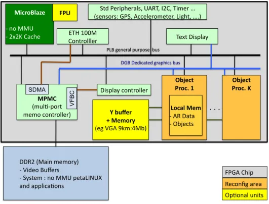
The system architecture is fully specified and tested at a cycle level, the VHDL implementation is completed and synthesized, moreover HW / Linux interfaces have been specified. The architecture, obtained after specialization and hardware/software partitioning, is described in Fig.9. The result is compact and flexible.
The architecture is mainly built around a softcore, which is a MicroBlaze (MB) in this study, running Linux (Petalinux) to simplify the access to standard peripherals (I2C, UART, Ethernet) used for network access and communications with sensors. According to the specific AR context, we made the choice to consider positioning and graphics at the object level. So, the processor is enhanced with some instances of a new accelerator called Object Processor (OP) that handles object positioning and drawing. The complete OP specification represents 16.000 lines of original VHDL code. Each OP is in charge of one or more objects. Video buffers are stored in DDR and memory access is implemented with the MPMC Xilinx fast memory controller. Each OP can access the video buffer through a dedicated VFBC port; each port is connected to a 32bits FIFO. The Xilinx MPMC component allows for 8 ports, which means that up to 4 OPs can be implemented. The Y-buffer may not be necessary; it actually depends on the number of simultaneously visible objects. However if we consider a 8km visibility along the Y-axis with a 1m resolution, which is a very good assumption according to [5] (5km max), then a 4Mbits memory is required. Regarding the Artix low cost, low power device (12Mbits on-chip memory) this solution can be implemented on a single reconfigurable chip. ! ""#$!%&'()!*+*,-./! 0 !1(2+,!345+-6! 0 !7.68+*!9!),!&&:!;+8'<=>:?! ')2!';;@(A'B,)6!! !"#$%&'()*+ 0 !),!&&:! 0 !$C$D!E'AF+! 782!G+-(;F+-'@6H!:I#JH!=$EH!J(*+-!K! %6+)6,-69!LG7H!IAA+@+-,*+8+-H!<(MF8H!KN/! !,!-++ %*4@B0;,-8!! *+*,!A,)8-,@@+-/! O;B,)'@!4)(86! .+/01*$++ 2+!*3%$4+ %+M!1LI!PQ*9R&S/! 5/6*#7++ ,$%#8+9+ N!N!N!! :,;+ #+A,)TM!'-+'! UJV!WXX&! E,)8-,@@@+-! "(6;@'.!A,)8-,@@+-! YGLI!EF(;! VF BC J+C8!"(6;@'.! SDMA 5/6*#7++ ,$%#8+<+ =%#('+!*3+ 0!I#!"'8'!! 0!OSZ+A86! "L3!"+2(A'8+2!M-';F(A6!S46! G<3!M+)+-'@!;4-;,6+!!S46!
Figure 9: Heterogeneous Multi-OP MPSoC Architecture
6.4 OP architecture
Control Unit The OP component is the main architectural contribution of the proposed design, it is described in Fig.11. Given new user attitude and position from the processor where positioning algorithms are implemented, each OP individually updates the position and the drawing of the objects it is in charge of. The CPU stores object initial coordinates and features (polygons geometry, colors and so on) in the OP local memory whose content is detailed in Fig.11. The CPU can decide the load of each OP and the choices of objects to be drawn according to user priorities and field of vision. The OP is a strongly optimized N bits architecture, where N can be decided at design time according to accuracy constraints (e.g. N=16 bits, 11 integer and 5 rational). The design has been focused on data locality and bandwidth optimization, and the whole computation is controlled with a 223 states FSM organized in 5 main stages (see Fig.10): 1) Attitude and position data acquisition and coordinate system transformations, 2) Object scaling and 2D projection, 3) Visibility tests and vertex color computation, 4) Polygon shape tests and color increment computation, 5) Polygon Drawing.
• !"#$%&'(!)*+,-*.! &/$/!/01%,+,-*.!! • !2**3&,./$'! +4+$'5! $3/.+6*35/-*.+! !!!78!+$/$'+!! • !9:;'0$! +0/<,.=!/.&!>?! )3*;'0-*.! !!!>8!+$/$'+!! • !@,+,:,<,$4! $'+$+!/.&! A'3$'B!0*<*3! 0*5)%$/-*.! !!!CD!+$/$'+! • !E*<4=*.! +F/)'!$'+$+! /.&!0*<*3! ,.03'5'.$! 0*5)%$/-*.! !!!GG!+$/$'+!! • !E*<4=*.! ?3/H,.=! !!!I7!+$/$'+!! J!@,+,:<'!
9:;'0$+! 7B!J@,+:<'!E*<4=*.+! *3,'.$'&!E*<4=*.+!!J@,+,:<'!K! 2*<*3'&!E,B'<+!J@,+,:<'!K!!
"0 1% ,+ ,-*. !L/ $' !I DMN!
Figure 10: OP Five Stage FSM
!"#$%&'!()*&%++*)! ,-./! !"#$%&'()*+,-&'.$ 0/$ 01$ 02$ "$ ,-.1! !/$%&'()*+,-&'.$ 0/$ 01$ "$ 345'1! 0/$ 01$ "$ 345'/! 0/$ 01$ "$ 0"$ 01$ 0#$ 02$ 03$ 04$ 0/$ 05$ 06$ 0"7$ 0""$ 0"1$ 0"#$ 08 9$ :% ;8 $!7 <" 3. $ =-*&(8)$ ! ! ! ! ! !!!!!!!!!!!0(6!(78%5!69:;%)!! $$$$$$$$$$$$$$$$$$$$$$$$$$$$$$$$$!"$>??8)$@$4$%&'()*+,-&'.$ "$ A0$$ BC0$ AD$ BCD$ BED$ AF$ BCF$ BEF$ G$ BCG$ BEG$ ()*&%++7<=!.<7'! :HI$!11#$'(J(8'.$ =IK$ H(J(*'$ >*<')*5!.<7'! HL'(8M$$F*'$ "#$%&'!3%?*)@!!?J(J.$ -*&:5!3%?*)@! =IK $ A-+J;$F*'$ 0DF$F*'$ N& (8 )+ -& &8 +($ G$O*P$F*'$ =-MM-&$?J(J$!;%9Q(R$J&9;8'SS.$ T-%&('$$ @ H(J,+$?J(J$!CLER$+-;-)'R$U.$ @ KL&JM%+$KJ(J$!CVLVEVR$+-;-)'VR$SSS.$ T-;L9-&'$'W8+%X+J,-&$ YOZ8+('$'W8+%X+J,-&$ A! >*CS$O*[8)$ A! BE0$
Figure 11: Graphic Object Processor Architecture
Processing unit An OP implements two specific Arithmetic and Logic Units (ALU), which are de-signed according to AR algorithm requirements. The first one has 3 inputs and 13 specific but simple instructions (e.g. fast implementation of division or increment operations), the second one has 2 inputs and 7 instructions (e.g. decrement with zero test). The architecture also includes two multipliers, 13 general-purpose registers and a register file with 16 places. This is an important point regarding data bandwidth and concurrent access requirements. A new component called the Incremental Pixel Shader (IPS) is introduced to apply the final step of the proposed method, which is based on horizontal and vertical color increments jointly with the double Bresenham method. It is mainly composed of registers with X,Y and Z increments, an ALU and a controller. Given Kpx and Kpz, IPS can increment polygon pixel values, this component directly computes RGB values for each pixel with 6 increment or move instructions.
Interconnections and memories The OP architecture is based five concurrent communication buses to face bandwidth requirements. The first bus is 32bits wide; it is connected to the local memory. The size of the memory is flexible according to application requirements (e.g. 5 objects with 20 points and 10 polygons each and N=16bits requires 39Kbits). Moreover the bus controller provides 1x32, 2x16 or 4x8bits accesses. This flexibility is intensively used to concurrently transfer 16 and 8bits data. The local memory is
depicted in Fig.11, it is organized in 5 regions. The first one contains common data including ambient light direction, number of objects and numbers of polygons. The second region contains point positions and light values, the static part stores initial point positions and the dynamic part is used for updated positions in the user coordinate system. The third region contains specification of polygons as a list of point addresses. The fourth region stores the specification of objects as a list of polygon addresses; it also includes some specific coefficients for the object light modeling. Finally the last region is a buffer used for temporary data. The second bus is 16bits wide and connected to the register file that can be accessed simultaneously with processing unit registers. The register file length is 16, it is used for the storage of temporary data produced and reused during processing. The third bus is the access to the Y-buffer, which is interfaced through a specific module designed to optimize the test of pixel depths. It works as follows: during the execution of the 4th stage of the processing flow (polygon shape test, color increments), the Y values of polygons are transferred to the Y-buffer interface that sends back a notification if the tested polygon is hidden by closer ones. In such a case, the current polygon processing is interrupted and a jump is executed to the next polygon processing. Finally, the fourth connexion is a RGB bus (24 bits pixel values), which is provided to access the video buffer.
Security aspects Some applications require the objects information to be kept secrets, if the softcore (CPU) is hacked then the main weakness is the link between the CPU and the OP local memory where objects are stored. So the access must be designed carefully. The local memory can be updated in various ways. First, the memory can be loaded at design time or at configuration time (from a encrypted Flash file), in such cases the architecture doesn’t implement any physical link between the CPU and the local memory, in that case no read or write access are possible from the CPU. When new objects must to be loaded according to the user environment, the Linux solution can provide the required secure network access (SSL), in this case only write operations are physically implemented and no program running on the CPU can read local memory data. If the chip is considered as a secure area, then this solution is efficient since no sensitive data are stored on external memory except the configuration that may be stored in on a encrypted flash memory [22].
H-MPSoC reconfiguration The architecture is such that multiple OPs can run in parallel since each of them works with a given collection of objects. The CPU and OPs are quite independent, since they rely on shared memory communications, so that the CPU can feed the OP local memories with new position data. So the architecture can be dynamically and partially reconfigured according to the number of objects and real-time constraints. If new FPGA devices can implement real low-power modes when the power consumption is negligible for unconfigured areas, then such a solution makes sense in terms of energy efficiency. As described in Fig.9, each OP must be placed in a dynamically reconfigurable area. Technically speaking, this solution is viable, the critical parts lie in the implementation of the two bus interfaces (VFBC, Y-buffer) that must be isolated from the reconfigurable area.
7
Results
In this section we provide and discuss results related to performance estimations, bandwidth use, implemen-tation cost on FPGA and power consumption.
7.1 Performances
First, the whole application flow has been described with a parameterized performance model that enables the counting of operations and transfers according to 25 variables such as the display format, the number and size of objects etc. Then, this model has been validated with some real profilings carried out on the target MB with and without floating point unit (FPU). The performance model of the hardware implementation is straightforward since the number of steps of the FSM is fully specified. Fig.12 gives the results with the following configurations:
!"#$$% !"#$&% !"#$'% !"#$(% !"#!)% I-Position/Attitude
control +Quaternion Rot. II-Coord. Conv. perspectives, line II-Object Proj., II-Polygo Shading, Pixel light Total !"#$%# !"&'()# !"&'()&*(# %+,-./-01#2%345# 67829:;6<4345#
Figure 12: Performance summary considering: 8 objects, 16 vertex/Obj., 13 triangles/Obj., VGA display, average 2D object size: 1/20 VGA, IMU acquisition rate: 50Hz, GPS rate: 5Hz
- ”SW+FPU”: MB with a floating-point unit.
- ”SW+FPU+OP IP”: MB with FPU and one OP unit.
In this example we consider a case, which goes beyond our case study requirements. Thus, in this configu-ration, we consider 8 objects, 16 vertices and 13 polygons per object, a VGA display, an average 2D object size equal to 1/20 VGA and a sensor (IMU MEMs) acquisition rate of 50Hz while the GPS acquisition rate is 5Hz. If we consider a 100MHz clock (100.106 cycles), we observe that the Positioning/Attitude control part of the application requires 70% of available cycles with the SW solution. The margin is too small to be safe within a Linux system where additional user processes are necessary. Moreover a FPU unit is of real value for matrix operations that have high precision requirements. The second solution ”SW+FPU” can also be considered for the Object positioning (steps 1.1,1.2,1.3) that requires around 2M of cycles, but the quaternion-based rotation of objects will be too greedy (66M cycles) and would lead to a total of 80% of CPU use. As expected, the graphic part of the application is definitely out of the scope of any processor-based implementation, except for the 2D projection steps (3.8M). But combined with previous application requirements, this operation cannot be mapped on the processor and the improvement would not make sense in terms of data locality. This means that the OP HW IP will handle all the graphic steps with a clear interface to the software positioning part that can feed the OP with filtered attitude and position data. The OP processor is then in charge of adapting objects drawing according to new data. Fig.13 gives the evolu-tion of performances for the three configuraevolu-tion. They are linear with the number and the size of objects, the size is given as a ratio of VGA frame. We observe that the performances of the OP implementation remain 3 orders of magnitude better than SW ones. These features can also be used to decide the number of OP to be implemented if necessary. Based on the previous assumptions, 40M cycles are required for a complete execution of the graphics part. Tables 2 and 3 give the implementations results of the OP HW IP on different Xilinx devices families: Virtex 5, 6 and Spartan 6. The last one exhibits the lowest clock frequency (73MHz), which means 73M available cycles and consequently a use rate equal to 55%. In the two other cases, the clock frequency is 120MHz and the use rate drops to 33%. As a conclusion we observe that a viable solution is a MB with a FPU, running an embedded Linux OS and enhanced with a HW OP IP. This architecture offers the expected performances to run augmented reality applications. We have also tested the Zynq case, which is different since this is an hybrid device based on a ARM dual-core Cortex A9 combined with FPGA (Artix 7 or Kintex 7) on a single chip. It means that a MB isn’t necessary anymore and only OP IPs are synthesized, moreover high-speed AXI links and a shared L2 cache are available for A9/FPGA communications, finally the processor can handle the video buffer.
Figure 13: Cycle count (Log. Scale) VS a) objet number and b) object size (VGA ratio)
Table 2: MB+FPU and OP implementations: Synthesis Results on FPGA. Number of slices or LUT slices / BRAM blocks / maximum frequency
Slices/Bram/F Virtex 5 Virtex 6 Spartan 6 Zynq (Artix)
Nb/Nb/MHz
MB+FPU 3305 / 20 / 120 2741 / 40 / 150 1842 / 8 / 100 - / - / 866 HW IP OP 1231 / 2 / 120 1048 / 2 / 120 1233 / 2 / 73 4016(LUTs)/ 2 / 88
7.2 Bandwidth use
The main design constraint was the access to storage units as well as the efficient ordering of computation so that data reuse is optimized. Fig.14 shows the use of local memory (RAM) and register file (RF) buses in each of the 5 five control stages. R, W and total means read, write and read+write accesses. 1 corresponds to 100% use, meaning that a transfer occurs every cycle. We observe that the bandwidth use of the register file is over 50% in stages 1 and 2, close to 100% in stages 3 and 4. It is not used in stage 5 anymore and this free slot can be used, if necessary, to update the memory content with new objects. The use of the register file bus demonstrates the efficiency of the implementation, it is very close to 100% in stage 5 and over 50% in all stages. RGB out is close to 100% as well in stage 5, it corresponds to the update of the video buffer, implemented in DDR, with new values of object pixels.
buses.pdf !
Table 3: Device Choice and Opportunities
nb of nb nb used used used Bram nb used
available of of slices Bram +Y-buff of BW
Slices Bram18 MB OP ratio ratio ratio MPMC ratio
Virtex 5 Min(LX30) 4800 64 1 1 0.95 0.34 3.86 1 0.08 LX50 7200 96 1 2 0.80 0.25 2.59 1 0.15 LX85 12960 192 1 4 0.63 0.15 1.32 1 0.30 LX110 17280 256 1 8 0.76 0.14 1.02 2 0.60 17280 256 1 4 0.48 0.11 0.99 1 0.30 LX155 24560 384 1 12 0.74 0.11 0.70 2 0.90 Max(LX330) 51840 576 1 12 0.35 0.08 0.47 2 0.90 Virtex 6 Min(LX75) 11640 312 1 4 0.60 0.15 0.88 1 0.30 LX130 56880 528 1 12 0.27 0.12 0.55 2 0.90 Spartan 6 LX25 3758 52 1 1 0.82 0.19 4.52 1 0.08 LX45 6822 116 1 3 0.81 0.12 2.06 1 0.23 LX75 11662 172 1 6 0.79 0.12 1.42 2 0.45 Max(LX100) 15822 268 1 8 0.74 0.09 0.93 2 0.60 Zynq (Artix) XC7Z010 17600 60 0 2 0.46 0.07 (3.82) (1) (0.15) XC7Z020 53200 140 0 6 0.45 0.09 (1.69) (2) (0.45) 7.3 Implementation Cost
The OP processor is specified as a VHDL code at RTL level. This code has been synthesized, placed and routed for four Xilinx devices. Synthesis results are given in Table 2 and projections on different FPGA devices and families are given in Table 3. The MB configuration implements a 4K I/D cache and usual peripheral controllers (UART, MPMC, Flash, Ethernet, VGA). Table 2 gives the number of slices and BRAM blocks required for MB+FPU and OP implementation and the maximum frequency clock after place and route. Fig.15 shows the required size of local memory that grows linearly with the number of objects and polygons. We observe that a OP is half the cost of a MB+FPU and that all implementations can reach 100MHz except for OP on Spartan 6 (73MHz). Note also that the results don’t include the Y-buffer memory, which are not synthesized on the FPGA in these cases. However it can be implemented as a buffer in the DDR, the consequence is that the computation of hidden polygons may be interrupted a few cycles later. Table 3 gives the number of OP that may be implemented on the different targets according to the number of available Slices and BRAM blocks. It also gives a ratio that includes the Y-buffer size considering a 12 bits depth (e.g.5Km, 1.25m resolution) and a VGA display (3.68Mb). The given ratios represent the used resources divided by the available ones on the chip. The used bandwidth metric takes into account all transfers between OPs and the external DDR memory including Y-buffer accesses, this metric is strongly dominated by pixel write accesses for updates (>99%). Note that we assume a very high video rate equal to the sensor rate, i.e., 50Hz. The Xilinx memory controller (MPMC) can manage up to 8 memory ports with different protocols (FIFO, DDR, cache,...), 4 ports are used by the MB, so 4 remain available for OP accesses to the DDR.
7.4 Implementations discussions
We can draw several conclusions from these results. We first observe that the smallest Virtex 5 could theoretically implements one OP but a usage of 95% of slices puts too much constraint on the routing step. However the next device (LX50) can implement two OPs. A LX110 is required to fully implement the Y-buffer on chip, such a chip can implement 4 OPs. With the next generation of Virtex 6, we note that the smallest device (LX75) is large enough to design a system with 4 OPs with an on-chip Y-buffer. A LX 130 can theoretically implement 48 OPS but is limited to 12 according to the memory bandwidth capacities. Virtex are expensive FPGAs while the Spartan family has been designed for low cost design that fit the context of embedded systems. We observe that a small LX25 Spartan 6 can implement 1 OP,
Figure 15: On-chip Memory Size vs number of Objects (7 polyg. /Obj) and Polygons (3 objects)
a LX45 provides enough resources for 3 OPs. The first solution that allows for an in-chip Y-buffer is the largest Spartan that can implement 12 OP according to bandwidth constraints. So low cost solutions with high performances are possible and more can be expected.
Xilinx has released in 2011 a new device generation that relies on a 28nm technology and brings significant power savings. This is especially true with the low-cost, low-power Artix 7 family that opens interesting perspectives. The positioning/control part of the application can be mapped on one A9 core, while 2 OPs can be synthesized on smallest Zynq device (XC7Z010).
7.5 Power and technologies considerations
Profiling-based power estimation shows that the power consumption of an OP is 100mA on a Zynq Z020 with a maximum activity and a 88 MHz clock frequency. The power consumption of the ARM processor running Linux is 185mA on the same device with the same voltage and a 866 MHz clock frequency. It means that a total power consumption remains lower than 300mA with an OP that fully occupy the available 88 Mcycles. In our case study only 40M are necessary, so about 50% of power savings could be obtained if power gating was efficiently applied.
If we compare with the Snowball implementation, we can consider that the BT and MEMS power consumption remain identical. So, the power difference is mainly due the Zynq and GPP+GPU (A9+Mali) implementations and corresponds to 95mA, it leads to power gains larger than 200mW.
We also made an estimation about a full implementation of the application on the Zynq ARM processor, with the best conditions, including no cache miss and no pipeline stall, we obtain to 600 Mcycles to be compared with the 40Mcycles of the OP co-processor, if we consider the relative clock frequencies (866/88 MHz) and computation only during computation, the OP energy efficiency si finally 15 times better.
This short study show that FPGA offer credible solutions. The power consumption of the OP coprocessor synthesized on a small Spartan LX25 is 85mA (0,111W) for instance while the MB with FPU consumes 1,12W. However in case of mass product devices, the OP coprocessor will be delivered as an IP available in an ASIC library. Then the final architecture can be based on a standard ARM A9 processor with one or more OP coprocessors. Without the overhead of reconfiguration capabilities and the possibility to take advantage of power gating a gain of one order of magnitude can be expected compared to GPP+GPU solutions. Such a solution would become viable in case of an exploding demand of chips to design self-content and energy efficient embedded systems for AR applications.
8
Conclusion
Few research work has been conducted in the domain of embedded system design for mobile augmented reality applications in the context of emerging light see-through HMD. In this project we have conducted an in depth algorithm/architecture study and designed a complete system according to strong footprint constraints. The solution that has been developed is dedicated but flexible. The approach has deliberately been focused on standard protocols and interfaces; it can be interconnected with usual inertial sensor and communication peripherals. This work results in a new approach for the design of AR-specific embedded and reconfigurable systems with three main contributions. The first one is the choice and the full specification of
a gyroscope-free set of algorithms for position and attitude estimation, this solution relies on the association and the adaptation, to the AR domain, of different previous contributions. The second one is the embedded system architecture, where is introduced a fast and simple Object Processor (OP) optimized for the domain of mobile AR. The architecture is especially optimized for data-reuse and flexible since objects can be distributed on a given number of OPs. Finally the OP implements a new pixel rendering method (IPS) implemented in hardware and that takes full advantage of Open-GL ES light model recommendations. The whole architecture has been implemented on various FPGA targets. The results demonstrate that expected performances can be reached and that a low-cost FPGA can implement multiple OPs. This solution is viable when reconfigurable architectures make sense but the ultimate solution for mass market products would be a chip including a GPP and multiple OPs with power gating capabilities. Current undergoing work focuses on the choice of objects to be displayed in the user field of view. This study is made jointly with ergonomists and based on user feedbacks. The choice of objects to display will be implemented as a software service that will be in charge of the local memory content.
Acknowledgments
This work has been supported by the DGA (french defense department) and has greatly benefited from discussions with Dr. John Williams about system architecture and Linux implementation on FPGA.
References
[1] J. Bijker and W. Steyn. Kalman filter configurations for a low-cost loosely integrated inertial navigation system on an airship. Control Engineering Practice, 16(12):1509 – 1518, 2008.
[2] J. Bresenham. Algorithm for computer control of a digital plotter. IBM Systems Journal, 4(1):25–30, 1965. [3] A. I. Comport, E. Marchand, M. Pressigout, and F. Chaumette. Real-time markerless tracking for augmented
reality: The virtual visual servoing framework. IEEE Trans. on Visualization and Comp. Graphics, 12(4), 2006. [4] S. Feiner, B. MacIntyre, T. Hollerer, and A. Webster. A touring machine: prototyping 3d mobile augmented reality systems for exploring the urban environment. In Wearable Computers, 1997. Digest of Papers., First International Symposium on, pages 74–81, 1997.
[5] M. Franklin. The lessons learned in the application of augmented reality. In RTO Human Factors and Medicine Panel (HFM) Workshop, West Point, NY, USA, june 2006. NATO.
[6] D. Gebre-Egziabher, G. H. Elkaim, J. D. Powell, and B. W. Parkinson. A gyro-free quaternion-based attitude determination system suitable for implementation using low cost sensors. Position Location and Navigation Symposium, IEEE 2000, pages 185–192, 2000.
[7] P.-F. Guo, H. Qiu, Y. Yang, and Z. Ren. The soft iron and hard iron calibration method using extended kalman filter for attitude and heading reference system. In Position Location and Navigation Symposium (PLANS), 2008. [8] A. Herout, M. Zacharias, M. Dubska, and J. Havel. Fractal marker fields: No more scale limitations for fiduciary
markers. In Mixed and Augmented Reality (ISMAR), 2012 IEEE Int. Symp. on, pages 285–286, 2012.
[9] J. Karlekar, S. Zhou, W. Lu, Z. C. Loh, Y. Nakayama, and D. Hii. Positioning, tracking and mapping for outdoor augmentation. In Mixed and Augmented Reality (ISMAR), 2010 9th IEEE International Symposium on, pages 175–184, 2010.
[10] K. H. Kim, J. G. Lee, and C. G. Park. Adaptive two-stage extended kalman filter for a fault-tolerant ins-gps loosely coupled system. Aerospace and Electronic Systems, IEEE Transactions on, 45(1):125–137, Jan. 2009. [11] J. Kingyens and J. G. Steffan. The potential for a gpu-like overlay architecture for fpgas. International Journal
of Reconfigurable Computing, 2011, 2011.
[12] W. Koo, S. Chun, S. Sung, Y. J. Lee, and T. Kang. In-flight heading estimation of strapdown magnetometers using particle filters. In National aerospace & electronics IEEE conference (NAECON), 2009.
[13] D. Li, R. J. Landry, and P. Lavoie. Low-cost mems sensor-based attitude determination system by integration of magnetometers and gps: A real-data test and performance evaluation. In IEEE Position Location and Navigation Symposium, 2008.
[14] A. Lingley, M. Ali, Y. Liao, R. Mirjalili, M. Klonner, M. Sopanen, S. Suihkonen, T. Shen, B. P. Otis, H. Lipsanen, and B. A. Parviz. A single-pixel wireless contact lens display. Journal of Micromechanics and Microengineering, 21(12):125014, 2011.
[15] M. A. Livingston, L. J. Rosenblum, S. J. Julier, D. Brown, Y. Baillot, J. Edward, S. Ii, J. L. Gabbard, and D. Hix. An augmented reality system for military . . . In In Interservice/Industry Training, Simulation, and Education Conference, page 89, 2002.
[16] J. Marins, X. Yun, E. Bachmann, R. Mcghee, and M. Zyda. An extended kalman filter for quaternion-based orientation estimation using marg sensors. In Intelligent Robots and Systems, 2001. Proceedings. 2001 IEEE/RSJ International Conference on, volume 4, pages 2003–2011 vol.4, 2001.
[17] K. Mirza and K. Sarayeddine. Key challenges to affordable see through wearable displays: The missing link for mobilearmass deployment. Technical report, 2012.
[18] A. Munshi, D. Ginsburg, and D. Shreiner. OpenGL(R) ES 2.0 Programming Guide. Addison-Wesley, 2008. [19] S. Nasiri. A critical review of mems gyroscopes technology and commercialization status. Technical report,
InvenSense, http://invensense.com/, 2010.
[20] E.-H. Shin and N. El-Sheimy. An unscented kalman filter for in-motion alignment of low-cost imus. In Position Location and Navigation Symposium, 2004. PLANS 2004, pages 273–279, April 2004.
[21] S.Wuytack, J-Ph.Diguet, F.Catthoor, and H. man. Formalized methodology for data reuse exploration for low-power hierarchical memory mappings. IEEE Trans. on VLSI Systems, 6(4):529–537, Dec. 1998.
[22] R. Vaslin, G. Gogniat, J.-P. Diguet, E. Wanderley, R. Tessier, and W. Burleson. A security approach for off-chip memory in embedded microprocessor systems. Microprocess. Microsyst., 33(1):37–45, Feb. 2009.
[23] A. Waegli, J. Skaloud, P. Tome, and J.-M. Bonnaz. Assessment of the Integration Strategy between GPS and Body-Worn MEMS Sensors with Application to Sports. In ION-GNSS 2007, 2007.
[24] X. Yang and K.-T. T. Cheng. Ldb: An ultra-fast feature for scalable augmened reality on mobile devices. In International Symposium on Mixed and Augmented Reality (ISMAR), 2012.