HAL Id: hal-01225771
https://hal.archives-ouvertes.fr/hal-01225771
Submitted on 7 Jun 2018
HAL is a multi-disciplinary open access
archive for the deposit and dissemination of
sci-entific research documents, whether they are
pub-lished or not. The documents may come from
teaching and research institutions in France or
abroad, or from public or private research centers.
L’archive ouverte pluridisciplinaire HAL, est
destinée au dépôt et à la diffusion de documents
scientifiques de niveau recherche, publiés ou non,
émanant des établissements d’enseignement et de
recherche français ou étrangers, des laboratoires
publics ou privés.
Split of Composite Components for Distributed
Applications
Ansgar Radermacher, Arnaud Cuccuru, Sébastien Gérard, Brahim Hamid
To cite this version:
Ansgar Radermacher, Arnaud Cuccuru, Sébastien Gérard, Brahim Hamid. Split of Composite
Com-ponents for Distributed Applications. Forum on Specification & Design Languages (FDL 2013), Sep
2013, Paris, France. pp. 1-6. �hal-01225771�
O
pen
A
rchive
T
OULOUSE
A
rchive
O
uverte (
OATAO
)
OATAO is an open access repository that collects the work of Toulouse researchers and
makes it freely available over the web where possible.
This is an author-deposited version published in :
http://oatao.univ-toulouse.fr/
Eprints ID : 12687
Official URL:
http://ieeexplore.ieee.org/xpl/mostRecentIssue.jsp?punumber=6636145
To cite this version :
Radermacher, Ansgar and Cuccuru, Arnaud and Gérard,
Sébastien and Hamid, Brahim Split of Composite Components for Distributed
Applications. (2013) In: Forum on Specification & Design Languages (FDL
2013), 24 September 2013 - 26 September 2013 (Paris, France).
Any correspondance concerning this service should be sent to the repository
administrator:
[email protected]
Split of Composite Components for Distributed
Applications
Ansgar Radermacher, Arnaud Cuccuru, S´ebastien G´erard
CEA, LIST,
Laboratory of Model driven engineering for embedded systems Point Courrier 174, Gif-sur-Yvette, F-91191 France
Email:{ansgar.radermacher, arnaud.cuccuru, sebastien.gerard}@cea.fr
Brahim Hamid
IRIT
University of Toulouse, France Email: [email protected]
Keywords : composite components, UML, distribution
Abstract—Composite structures as in UML are a way to ease the development of complex applications. Composite classes contain sub-components that are instantiated, interconnected and configured along with the composite. Composites may also contain operations and further attributes. Their deployment on distributed platforms is not trivial, since their sub-components might be allocated to different computing nodes. In this case, the deployment implies a split of the composite. In this paper, we will motivate why composites need to be allocated to different nodes in some cases by examining the particular case of interaction components. We will also discuss several options to achieve the separation and their advantages and disadvantages including modeling restrictions for the classes.
I. INTRODUCTION
The basic idea behind any component-oriented approach is that elementary application pieces (i.e. components) can be composed together in order to achieve the functionality of a more complex system. Component-oriented approaches are usually grounded on a design process including component development or reuse, assembly and deployment.
In the component assembly step, the system under design is itself considered as a component. It is hierarchically defined by an assembly of existing components using an Architec-ture Description Language (ADL), where the assembly is concretely specified by connections expressed between sub-components (parts). In the context of this paper, we focus on UML as modeling language. Sub-components can themselves be defined as assemblies, resulting in hierarchical systems of arbitrary depth.
In the deployment specification step, the target execution platform for the application is considered. The model of the execution platform usually consists, at least, of an identifi-cation of the various execution nodes, as well as available communication paths between them. The deployment specifi-cation consists of allocating the components of the applispecifi-cation model to execution nodes of the platform (often indirectly by allocating them to processes or threads which in turn are allocated to execution nodes, but we simplify this aspect in the context of this paper). Allocation is usually done taking into account non-functional requirements of the system under design, such as execution time constraints, memory footprint, communication throughput, etc.
It is sometimes necessary to allocate sub-components to dif-ferent execution nodes which requires a split of the associated composite. The next section illustrates this problem by means of a small example, section III provides multiple options how to split composites. Section IV examines how existing component frameworks split composites. An evaluation and comparison of these options is given in section V. Section VI concludes this article.
II. MOTIVATINGEXAMPLE
In this section, we motivate why some composites need to be split by examining interaction components.
Consider a very simple application with two components, A and B as shown in Fig. 1. A has a port q with a required interface MyIntf, B has a port p with a provided interface MyIntf.
Figure 1. Simple example system
Now consider that the communication between A and B is realized by a component that implements the interaction on top of the operating system’s socket API. We call such a component an interaction component (also called connector in the context of the DDS-for-CCM specification [8]). On a logical level, this component is a single entity that may contain configuration data such as a port number, connection policies or a unique identifier (object reference).
If we want to distribute the application onto two nodes, a and b are allocated to different nodes. Fig. 2 shows the archi-tecture of the example system. Please note that the composite structure diagram distinguishes between a role (corresponding to a kind of instance) and its type, i.e. the socket is not a nested classifier within the system but a part of the system on an instance level. Thus, the first component that is split is the component representing the system itself. However, the
Figure 2. Simple example system with socket and allocation
system component is a particular case, since there exists only one instance, it has no behavior of its own and there are no connections from the system boundary to inner parts (called delegation connectors in UML). Thus, it is a pure assembly component and basically used to define the instances of a system and their interconnections.
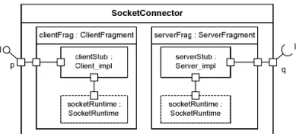
Fig. 3 shows the internal structure of the socket connector. It consists of a client and server stub which both access a socket run-time. The dashed outline of the latter indicates that this component is shared: it is not instantiated along with the socket connector but exists independently. The access to a shared resource within a composite corresponds to a kind of vertical connection: the communication of the stubs with the run-time is a communication between different layers, pre-assembled within the composite.
Since the communication with the interaction component is a simple local communication, the interaction component itself needs to be separated. We can further follow local connections within the connector to determine the allocation of the internal parts of the connector. The allocations within the socket connector can thus be derived from the allocations of the application components: the client fragment of the connector needs to be co-located with A and the server fragment with B. An interesting aspect is the socket run-time that is shared by client and by server fragment. Whereas it exists only once from a logical viewpoint, it must be present on each node and thus be allocated to NodeA and to NodeB. Fig. 4 shows the resulting split of the socket connector.
Figure 3. Internal structure of socket connector
Since a composite can enable distribution, its split should
be authorized under the condition that this split does not modify the component’s semantics. This is the case, if a composite does not have a behavior of its own (only delegation to parts), nor any configuration data. Since the latter is too strict, the composite may offer virtual configuration attributes that are effectively realized by its parts. This means that the configuration attributes of the composite are linked with configuration attributes in the parts. The same attribute might appear in multiple parts.
Figure 4. Splitting a composite during distribution
Now consider a slight extension of the example: B also talks to A, using the same interface, A has an additional port p, B an additional port q and both are connected, as shown in Fig. 5.
In this case two parts (connAB and connBA) are typed with the SocketConnector. But, the allocation of the sub-part is different for the two instances (parts):
Since a is on NodeA, the clientStub part of the instance
connAB must be on NodeA as well to satisfy the co-localization constraint caused by the assumption of insepa-rable simple connections. But with the same argument, the clientStub of instance connBA must be on NodeB, co-localized with b. Thus, allocation is instance based and it might happen that two different instances of a composite have different allocation specifications for their parts. Thus, the split is not trivial and we will study multiple options how to split the composite in case of the example in section III.
Figure 5. Bidirectional communication
III. DIFFERENT WAYS TO SPLIT COMPOSITES
In the sequel, two different options to split composites are shown by means of the simple example from section II.
a) Option 1 – keep composites: The first option is to keep a modified variant of the composite that only contains the subset of parts which are deployed on a certain node. Fig. 6 shows the result for the uni-directional variant of the example: SocketConnector’ is the variant of the original SocketConnec-tor. It contains the subset of parts that are allocated on NodeA, the clientStub and the socketRuntime. Note that splitting is in general not trivial, since the split must also consider super-classes. In our case, the ports of the socket are inherited by an abstract interaction component (aka connector type). Depending on how the super-class is organized, the composite only inherits from a subset of super-classes or super-classes need to be split as well which complicates the design.
Figure 6. Option 1: keep composite, uni-directional example
Please note that it is not the part which is allocated on a certain node, but the (sub-) instance that is associated with a part. If there is a second instance whose sub-instances are allocated in a different way, a second variant of the composite with a part subset must be created. This is shown in Fig. 7. The creation of multiple variants implies a certain overhead which –although small– may be non-acceptable on resource constraints systems.
Figure 7. Option 1: keep composite, bi-directional example
b) Option 2 – Flatten composite: A composite compo-nent may disappear in the deployment model, i.e. it is replaced by its internal structure. The internal assembly connections of a composite become assembly connections of the containing composite (the System class in case of the example). The delegation connections1 refine the final targets of existing assembly connections in the containing composite.
Fig. 8 shows the example system for NodeA, in which the socket composite has been flattened. The two parts in the system typed by a socket implementation have been replaced by parts that are directly typed with elements of the socket implementation. The original composition hierarchy may still be visible via a suitable naming convention for these new parts
1Assembly connectors are connections between inner parts, delegation
connectors connections from the composite to an inner part.
by prefixing them with the original part name, as done in the example with the prefixes connAB and connBA.
Whereas the transformation towards a model having only monolithic components and assembly connections2 is rather straight forward, the resulting system is different, as internal connections become visible in the system. This may be an-noying, if the same composite is instantiated more than once in the original model, e.g. if we have more than one socket connector. Also note that the internal structure of an interaction component might be more complex than the simplified socket connector used for illustration purposes.
This makes it a bit difficult to link it with the original model, for instance when debugging is done on the level of the deployed model, but fixes must be made in the original design model. Other tasks that are affected by this difference are for instance trace mechanisms (which must translate a trace specification for a composite into suitable specifications for the inner parts) and the replacement of a composite implementa-tion with another one (e.g. in the context of different system configurations). The advantage is a slightly reduced footprint and a resolution for the splitting problem.
Figure 8. Option 2: Flatten composite
c) Option 3 – Flatten composite, require explicit frag-ment sub-components: The third option is a variation of the second solution. We also flatten the Socket composite, but require that the composite must contains exclusively specific sub-components that we call fragments. A fragment encapsu-lates the parts of a composite that are allocated on the same node, conversely each fragment within a composite is typically allocated on a different node. The latter implies a restriction that is verified by a validation rule: fragments may not be connected by UML assembly connectors. The modeling of the socket connector with fragments is shown in Fig. 9.
The resulting system is shown in Fig. 10. The composite has been flattened; the fragments have become top-level elements. The result looks very similar as the solution in Fig. 7, ef-fectively the explicitly modeled fragments replace the derived subsets of the composite.
The advantage of this solution is that a possible split is anticipated and explicitly defined by the developer. Since the
2In UML-like languages, connectors are always owned by a composite, i.e.
Figure 9. Option 3: Socket connector with explicit fragments
Figure 10. Option 3: Flatten split composites, require fragments
composite may not have assembly connectors, no additional connectors are added to the system class (the composite that contains the split composite).
IV. BACKGROUND ANDRELATEDWORK
In the sequel, we sketch existing component frameworks that have a specific support for interaction components, since these need to address the composite split in a systematic way. We then show how these frameworks handle composite splitting.
A. Component models with dedicated interaction components (connectors)
The connector element that we have used in the motivating example is supported in multiple component models. As already mentioned, it has been standardized within the context of the OMG (Object Management Group) standard CCM (CORBA component model [6]. More specifically, it is part of the DDS for CCM [8] specification, enabling component interactions via OMG’s Data Distribution Service. Within this specification, the term GIS (generic interaction support) is introduced. GIS will be part of the upcoming OMG unified component model [9]. The underlying connector extension for CCM has been proposed in [11]. Deployment with CCM is based on the specification deployment and configuration (D&C) of distributed component-based applications [7]. This standard describes a so-called deployment plan, a specification of instances that refer to component implementations, the interconnections between these instances, their configuration and their allocation to a node.
Connectors have also been introduced in the context of Fractal [2]: a binding is defined as a communication path between component interfaces. Bindings can be primitive or
composite. A primitive binding (direct connector) binds one client interface and one server interface in the same address space. A composite binding is a communication path between
an arbitrary number of distributed component interfaces and is represented as a set of primitive bindings and binding com-ponents. Binding components are called Fractal connectors, and are normal Fractal components, whose role is dedicated to communication.
In SOFA [3], [1], connectors are used to support transparent distribution of applications. A connector might support a transport mechanism such as CORBA or bare sockets. In this context, they are responsible for marshalling and unmar-shalling and interfacing with the transport layer. But they can also be used for synchronization or interception. Connectors are automatically generated.
The FCM [4] (Flex-eWare component model) component model has the objective to unify the component models of Fractal and CCM. It extends the UML composite structures with dedicated interaction components – as the for instance the socket connector presented in the example – flexible ports and container services. This component model is supported by an add-on to the Papyrus3 UML modeler called Qompass designer. This add-on was first introduced as eC3M (embedded Component Container Connector Model/Middleware) [10]. Upon deployment, the tool chain executes a model trans-formation that replaces annotated UML connectors with the associated interaction components, as shown in the example. This transformation includes an instantiation of the interaction component to the context in which it is used (similar to the generation of in SOFA). A further model transformation pro-duces a model per node. During the latter, composites within FCM models are split. The composites that are concerned are mainly interaction components and the dedicated system component.
B. Support for splitting composites in existing frameworks
In this section, we study how existing component frame-work support splitting, mainly in the context of interaction components.
In the DDS for CCM specification, DDS interaction compo-nents are not identified as composites, since there are separate writer and consumer components. This is useful in case of DDS in which connections are implicitly created by sharing the same topic, i.e. there is no single component that represents an interaction. But the generic interaction support enables explicit point-to-point interactions for which composites would be useful. D&C supports two kinds of implementations of software components:
• Monolithic implementations, where the code of the com-posite component is compiled as a single block. • Assembly (composite) implementations, including the set
of implementation of all the parts that the composite component includes. There must eventually be monolithic implementations at the “leaves” of the hierarchical imple-mentation. Assembly allows dependent packages to be deployed on distinct target nodes, enabling flexibility in composite component instantiation.
While the specification allows composites, the composites have no identity and cannot be reused. This has been ana-lyzed in [5]. In this article, the authors review and compare the ability of 13 component models of handling component composition. They identify the development with D&C as a “deposit only” repository for composites: a composite com-ponent that results from the comcom-ponent assembly step can be deposited in a repository but cannot be retrieved from it, because it does not have an identity of its own. In the end, only monolithic components are deployed, i.e. the component hierarchy is flattened. Note that this does not only apply to interaction components but to all composite components, even if they deployed on the same node, i.e. a stronger variant of the flatten option in section III.
In SOFA, the connector plugging is performed after com-ponent instantiation using a split of the connector into two parts: server and client connector units (fragments). Whenever component interfaces query a connector reference, the corre-sponding server connector unit is returned (instead of returning a reference directly to an interface). Similarly, whenever an interface is being connected to another component, a client connector unit is created and bound. The connector composite specifies the parts, into which it is later split explicitly, corresponding to the fragment option.
In Qompass, interaction components with explicitly identi-fied fragments are flattened, i.e. the fragment option. Being based on UML, Qompass must handle the specific case of a dedicated system component. Such a component is required, since connections can only be defined in the context of an enclosing composite (unlike for instance in D&C). Thus, Qom-pass must also split the system component, if the contained components are deployed on different nodes. The approach that has been chosen is to create a specific variant of the system component on each node, i.e. the keep option. Note that it is not possible to flatten the system component, since the UML component model requires an enclosing composite for defining connections.
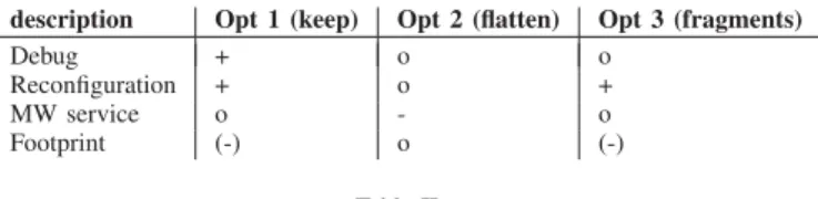
V. PRO AND CONS OF EACH SPLIT OPTION
The different options to split composites have different prerequisites and implications. For instance, flatten is evidently not possible for a top-level component, as shown in the preceding section. Splitting is problematic, if a composite is within an inheritance hierarchy, since it would require splitting super-classes as well (and thus likely producing a large number of variants of these classes). In this case, flattening is an alternative, if all super classes are component types, i.e. only adding ports and attributes.
An implication of splitting is that it increases the number of classes whereas flattening makes top-level composites bigger, since these have to incorporate the contents of a flattened component (sub-components and their connections) instead of the component itself.
A measurable implication is the footprint associated with the different ways to split. The code size of a complete application
code size (bytes) Opt 1 (keep) Opt 2 (flatten) Opt 3 (fragments) Simple example 13904 12233 13936
Simple bi-direct 14668 13754 14710 Table I
FOOTPRINT OF DIFFERENT DEPLOYMENT OPTIONS
description Opt 1 (keep) Opt 2 (flatten) Opt 3 (fragments)
Debug + o o
Reconfiguration + o +
MW service o - o
Footprint (-) o (-)
Table II
PROS ANDCONS OF DIFFERENT DEPLOYMENT OPTIONS
has been measured in case of the simple example and the bi-directional variant for options 1, 2 and 3, as shown in table I. The results were obtained on a Linux machine with gcc 4.7 (optimizations disabled). As expected, flattening results in a slightly smaller footprint compared to the other two.
Table II shows the advantages and disadvantages of the different options, As said earlier, keeping the original com-position hierarchy has the advantage that the deployed model is closer to the original architecture and thus a bit easier to debug. Re-configuration is also easier: if we want to replace the socket connector with another interaction component, we don’t need to remove additional assembly connections from the system.
VI. CONCLUSION
We have shown that the deployment of composite instances which are partly allocated on one node and partly on another can be tackled in several ways with different advantages and disadvantages. The choice of a suitable split option depends on properties of the composite that should be split. For instance, in Qompass designer we keep the composite of the System component, since this particular component (no inheritance, single instance) can be split easily and since flattening would result in multiple top-level components. On the other hand, we flatten interaction components and require the explicit use of fragments, since we want to avoid the problems that come with multiple instances (creating potentially multiple variants of a split component). The choice depends also on the deployment goals, e.g. whether an optimized application compared to a debug-enabled application should be delivered. The options are rather evident, but –to our knowledge– the task had not been examined systematically earlier.
The interest of deploying composites with complex alloca-tion properties is not artificial: a composite definialloca-tion is a suit-able choice for interaction components enabling distribution. In this context, the raised issues concern principally framework and tool developers, i.e. developers of interaction components and developers of model transformations associated with the split of composites. However, the results also apply to a sub-system modeled by composite classes that need to be allocated
on multiple execution nodes. In this case, system modellers or designers are concerned since they need to respect restrictions associated with the split of a composite and should know the consequences of different split options.
REFERENCES
[1] D. B´alek. Connectors in Software Architectures. PhD thesis, Charles University Prague, Faculty of Mathematics and Physics; Department of Software Engineering, Feruary 2002.
[2] E. Bruneton, T. Coupaye, and J.B. Stefani. The Fractal Component
Model, 2004. http://fractal.objectweb.org/specification/.
[3] Tom´aˇs Bureˇs and F. Plasil. Communication style driven connector configurations. In Lecture Notes in Computer Science, volume 3026, page 102–116, 2004.
[4] M. Jan, C. Jouvray, F. Kordon, A. Kung, J. Lalande, F. Loiret, J. Navas, L. Pautet, J. Pulou, A. Radermacher, and L. Seinturier. Flex-eWare: a flexible model driven solution for designing and implementing em-bedded distributed systems. Software: Practice and Experience, 42(6), 2011.
[5] K.-K. Lau and Z. Wang. Software component models. IEEE Trans. on
Software Engineering, 33(10):709–724, October 2007.
[6] OMG. CORBA Component Model Specification, Version 4.0, 2006. OMG Document formal/2006-04-01.
[7] OMG. Deployment and Configuration of Component Based Distributed
Applications, v4.0, 2006. OMG document formal/2006-04-02. [8] OMG. DDS for Lightweight CCM, v1.1, 2011. OMG document
ptc/2011-01-14.
[9] OMG. Unified Component Model for Distributed, Real-Time and Embedded Systems, Request For Proposal Draft, 2013. OMG document mars/13-05-03.
[10] A. Radermacher, A. Cuccuru, S. Gerard, and F. Terrier. Generating Execution Infrastructures for Component-oriented Specifications With a Model Driven Toolchain – A case study for MARTE’s GCM and real-time annotation. In Eighth International Conference on Generative
Programming and Component Engineering (GPCE’09), pages 127–136. ACM press, 2009.
[11] Sylvain Robert, Ansgar Radermacher, Vincent Seignole, S´ebastien G´erard, Virginie Watine, and Franc¸ois Terrier. Enhancing Interaction Support in the CORBA Component Model. In Achim Rettberg, Mauro C. Zanella, and Franz J. Rammig, editors, From Specification
to Embedded Systems Application, IFIP TC10 Working Conference: International Embedded Systems Symposium (IESS). Springer, 2005.