HAL Id: hal-01599392
https://hal.archives-ouvertes.fr/hal-01599392
Submitted on 6 Oct 2017
HAL is a multi-disciplinary open access
archive for the deposit and dissemination of
sci-entific research documents, whether they are
pub-lished or not. The documents may come from
teaching and research institutions in France or
abroad, or from public or private research centers.
L’archive ouverte pluridisciplinaire HAL, est
destinée au dépôt et à la diffusion de documents
scientifiques de niveau recherche, publiés ou non,
émanant des établissements d’enseignement et de
recherche français ou étrangers, des laboratoires
publics ou privés.
Using Power-Hardware-in-the-Loop Experiments
together with Co-simulation for the Holistic Validation
of Cyber-Physical Energy Systems
van Hoa Nguyen, Yvon Besanger, Quoc Tran, Cédric Boudinnet, Tung Lam
Nguyen, Ron Brandl, Thomas Strasser
To cite this version:
van Hoa Nguyen, Yvon Besanger, Quoc Tran, Cédric Boudinnet, Tung Lam Nguyen, et al.. Using
Power-Hardware-in-the-Loop Experiments together with Co-simulation for the Holistic Validation
of Cyber-Physical Energy Systems. IEEE PES International conference of Innovative Smart Grid
Technologies ISGT Europe 2017, Sep 2017, Torino, Italy. �hal-01599392�
Using Power-Hardware-in-the-Loop Experiments
together with Co-simulation for the Holistic
Validation of Cyber-Physical Energy Systems
Van Hoa NGUYEN1, Yvon BESANGER1, Quoc Tuan TRAN2, Cédric BOUDINNET1, Tung Lam NGUYEN1,2, Ron BRANDL3, Thomas I. STRASSER4
1
University Grenoble Alpes, G2Elab, F-38000 Grenoble, France CNRS, G2Elab, F-38000 Grenoble, France
2
CEA-INES, 50 Avenue du Lac Léman, 73370 Le Bourget-du-lac, France
3
Fraunhofer Institute of Wind Energy and Energy System Technology, Kassel, Germany
4
AIT Austrian Institute of Technology, A-1210 Vienna, Austria Email: [email protected]
Abstract—Composed of a large variety of technologies and ap-plications with unprecedented complexity, the smart grid, as a cyber-physical energy system, needs careful investigation of the in-teractions between the various domains involved, especially the coupling between the power and information systems. In this pa-per, two modern ways of modeling and simulating complex cyber-physical energy systems are considered: Co-simulation and Power-Hardware-in-the-Loop experiments. An analysis of these two ap-proaches shows that a complementary and joint setup with realistic behaviors of hardware equipment under a variety of complex envi-ronments, co-simulated by several simulators from different do-mains, create a complete and high performance environment to achieve a holistic approach for smart grid validation and roll out. In the scope of coupling these two techniques, major technical chal-lenges are identified and advanced solutions are outlined.
Index Terms—Co-simulation, Cyber-Physical Energy Sys-tem, Holistic Validation Approach, Power-Hardware-in-the-Loop, Smart Grid Systems Testing.
I. INTRODUCTION
A variety of changes and developments have been carried out during the past, presenting a portfolio of initiatives and perspectives of different smart grid solutions on European but also on international level [1]–[3]. In general, an increased consumption of electricity, with important peak loading due to electrification of transport is expected [1]. The decarbonized scenario requires a high penetration of distributed and renew-able energy resources, over levels of 15% to 20%, leading to an increasingly difficulty to ensure the reliable and stable management of electricity systems [3]. The integration of In-formation and Communication Technology (ICT) into the electrical energy infrastructure, along with smart metering is shifting from demonstration phase to large scale deployment. This will have a strong impact on system architectures as well as it raises concerns about cyber-security issue. The electric power grid integrated with communication systems and dis-tributed energy resources (solar, heat, etc.) has become a
cyber-physical energy system (smart grid) nowadays.
A general framework for smart grid validation and roll out, which takes into account their mutual interactions and
interde-pendencies, is required. One of the main barriers to this has been the lack of design and validation tools that are capable of analyz-ing power and communication systems in a holistic manner.
Extending power system simulation tools for the ICT do-main, or vice versa, demands a lot of effort and collaboration among experts of both areas, because the life cycle and tech-nical specifications of the electrical and communication equipment (in terms of reliability requirements, round trip time, determinism, temporal consistency and hierarchy) are signifi-cantly different. By creating a so-called co-simulation envi-ronment for the integrated analysis of both domains, via means of ad-hoc connections or in a master/slave fashion, one can un-derstand the impacts of different communication solutions used for the operation of power systems much better. Although sim-ulation architectures may vary, a co-simsim-ulation framework al-lows in general the joint and simultaneous investigation of models developed with different tools, in which the intermedi-ate results are exchanged during the execution of the simula-tions. However, the sub-systems are usually solved inde-pendently by their corresponding domain-specific simulators [4]. Co-simulation allows to have a complete view of both network behavior and the physical energy system states, while power system and communication networks are simulated with the most suitable solver and the calculation loads are shared.
Power-Hardware-the-Loop (PHIL) technology is in-creasingly used by the industry and the research community for testing hardware components, devices or systems in real conditions and scale, where a part of the whole test compo-nents are simulated in a Digital Real-Time Simulator (DRTS) [5]. The PHIL approach allows a safe and repeatedly testing of a device also in faulty and extreme conditions without damag-ing lab equipment, while providdamag-ing also flexibility in settdamag-ing up the test setup in transient and steady state operation [5], [6]. In the European ERIGrid project, a survey was addressed to the experts in 12 top European power and energy systems re-search institutions about mandatory future improvements of PHIL technology1. 63.6% of the experts stated that the power and software interfaces in PHIL technology should be
181.8% have PHIL testing capacity, in which 54.5% are in
proved to enable the capacity of remote/distributed testing and integration with co-simulation.
In this paper, we explore the possibilities of integrating PHIL in co-simulation in order to enable a holistic evaluation of smart grid solutions (addressing mainly power and ICT domains). By offering experiments very closed to real situa-tions, this approach provides an important tool during the de-sign, implementation and roll out of smart grid technologies, solutions and corresponding products. Beyond the added value to testing methods, this approach would also offer internation-al and multi-laboratory cooperation, which in turn, have a pos-itive impact to interoperability and confidence in the applica-bility of the researches under different grid conditions.
The main parts of the paper are structured as follows: The fundamental points of PHIL and co-simulation relevant for this investigation are outlined in Section II. A general archi-tecture is also proposed in this section. Major technical obsta-cles towards a seamless integration of PHIL and co-simulation are discussed in Section III together with possible solutions. The paper is concluded with a discussion and an outlook about future research in Section IV.
II. INTEGRATION OF PHIL AND CO-SIMULATION
In this section, we outline the principal elements of the co-simulation and the PHIL approaches followed by a generic ar-chitecture for an integration of them.
A. Co-simulation of Power and ICT Systems
Most of the work related to co-simulation in the field of smart grid solutions is mainly related to the necessity of inter-connecting power system and communication network simula-tions. As the traditional passive electric power grid (with uni-directional power flows) evolves towards and active power sys-tem (with bi-directional power flows), the existing energy in-frastructure suffer from several drawbacks (fragmented archi-tecture, lack of adequate bandwidth for two-way communica-tion, in-ability to handle the increasing amount of data from smart devices, etc.) [7]. It is therefore crucial to take the com-munication network in the development of smart grids – in terms of efficient topology, latency and security – into account. Usually, communication networks used in the context of lab experiments have very low latency due to short geographi-cal distances. This does not reflect real scenarios whereas the long geographic distance between different, networked devic-es may cause unexpected delays and signal lossdevic-es rdevic-esulting in an unexpected and faulty control behavior. Therefore, the communication network is usually separately analyzed using dedicated software tools in order to study the effect of realistic latencies, packet losses or failures in the ICT/automation sys-tem [8]. Communication simulators facilitate also cyber-security related investigations, such as denial-of-service pro-tection, confidentiality and integrity testing.
Co-simulation of the power and the communication system for an integrated analysis of both domains is however, not an easy task since the synchronizing of both simulation packages during runtime is required. Moreover, existing simulation tools are usually provided limited coupling possibilities with external tools; an adequate and suitable Application Programming
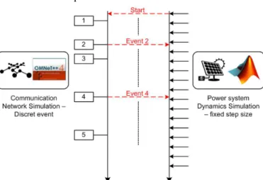
Inter-face (API) is often missing. On top of that, the fundamentally different concepts behind power and communication systems are also a challenge; detecting, linking, and handling related events in both domains can be a complex task (cf. Fig. 1)2:
• Power system simulation is usually continuous with the possibility of detecting events associated to values cross-ing a certain threshold.
• Communication network simulation is based on discrete events whose occurrence usually unevenly distributed with respect to time. Corresponding domain-specific sim-ulators provide an event scheduler to record current sys-tem time and process the events in an event list.
Fig. 1. Time synchronization between power and communication simulation.
Once an event occurs, the associated information is passed to the other domain where the other simulator will create the reaction. A co-simulation framework then has to execute some algorithms to ensure the synchronous and deterministic execu-tion of both domains simultaneously. Scientists have come up with various methods and techniques to deal with the synchro-nization issue. We can classify them into four main synchroni-zation techniques:
• “Offline” Co-simulation or “Model Exchange”: In this approach, the model of power system is exported to C-codes and then be compiled and imported to the network simulator for co-simulation. This is usually used as an al-ternative when direct co-simulation is hard to achieve.
• Master-Slave: In this approach, one simulator (usually the communication simulator, due to discrete timeline) is given higher priority and will coordinate the co-simulation steps.
• Point-based or time-stepped method: The individual sim-ulators run their simulations independently but pause at fixed synchronization points where information is ex-changed between simulators. In this approach, a middle-ware is normally needed.
• Global Event-Driven: In this approach, a global event list is created by mixing up the power system iteration steps with the communication network events according to their timestamps. Then only one simulator is allowed to
2
The software mentioned in the figures is representative and serves only for illustration purpose, to aide with reader comprehension. They are, by no mean, suggestion or recommendation from the authors for simulator selection.
ceed at a time and the other will halt. This structure leads to a limited speed of co-simulation.
A quite general review of existed works on the co-simulation of power and communication systems can be found in [7]–[9]. Generally, one can acknowledge two different structures of co-simulation:
• Ad-hoc Co-simulation: Most of the work in the literature falls into this category (usually coupling directly one power system simulator and one communication network simulator).
• Co-simulation with Master Algorithm: In this approach, a master algorithm (e.g., HLA [10]) or a co-simulation frame-work (e.g., mosaik3, Ptolemy4) will orchestrate the process. This master algorithm is responsible for synchronizing dif-ferent timelines of involved simulators and for directing the information exchange among simulator’s inputs/outputs. In order to improve interoperability and reusability of the models developed in co-simulation frameworks mainly two major standards have been issued: Functional Mockup
Inter-face5 (FMI) and High Level Architecture framework (HLA)
[10]. While FMI is oriented towards model exchange and the coupling of simulators for co-simulation, HLA provides a kind of master algorithm to orchestrate the co-simulated processes (which is addressed as “federate”). It appears that while both standards serve for co-simulation, FMI and HLA are not ex-actly at the same level of abstraction. Individually, HLA al-lows highly parallelized simulations of large-scale systems, but introduces additional time-synchronization issues [8].
B. Power-Hardware-in-the-Loop Experiments
The high ratio of Distributed Energy Resources (DER) in-tegration in a decarbonized scenario leads also to technical dif-ficulty to preserve the security and reliability of the network operation and to ensure the fulfilment of the established volt-age quality standards [11]. The Hardware-in-the-Loop (HIL) approach used in the power and energy systems domain is an efficient testing method for DER devices, for manufacturers to adapt their products to the increasingly demanding require-ments, as well as for network operators and regulation authori-ties to establish new testing and certification procedures [6], [11]. In this approach, a real hardware setup for a domain (or part of a domain) is coupled with a simulation tool to allow testing of hardware or software components under realistic conditions. The execution of the simulator in that case requires strictly small simulation time steps in accordance to the real time constraint of the physical target. Since the HIL approach usually involve coupling of different domains, it deals with quite similar challenges as co-simulation. On the other hand, HIL provides the advantage of replacing error-prone or in-complete models with real-world counterparts and the possi-bility of scalable testing in faulty and extreme conditions.
HIL in smart grids is generally classified into Controller Hardware-in-the-loop (CHIL) and
3 http://mosaik.offis.de/
4 http://ptolemy.eecs.berkeley.edu/ 5 https://www.fmi-standard.org/
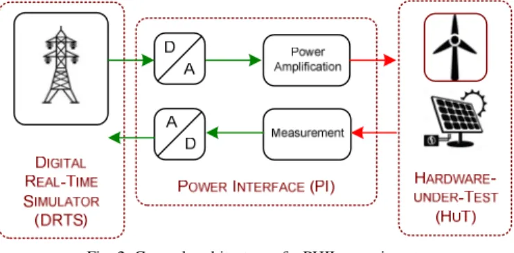
loop (PHIL) experiments [5], [6], [11]. CHIL involves in test-ing of a device (usually a controller) where signals are ex-changed between a DRTS and the device under test via its in-formation ports. The interface consists most of the time only Analogue to Digital and Digital to Analogue converters. In contrary, PHIL involves in testing a device which absorbs or generates power (e.g., inverter-based DER). A power interface is therefore necessary (see Fig. 2). In this paper, the focus is mainly on the PHIL approach.
Fig. 2. General architecture of a PHIL experiment.
A general PHIL setup consists of three main elements: (i) the DRTS, (ii) the Hardware-under-Test (HuT), and (iii) the Power Interface (PI):
• The DRTS computes the simulation model and offer I/O capacities. As aforementioned, the simulation time-step of the DRTS must be small enough to reproduce the behav-ior of the simulated system under dynamic condition (Fig. 3). The simulator allows designing and performing vari-ous test scenarios with a great flexibility.
• The HuT is usually a wide variety of different DER de-vices and networks (e.g., inverter-based DER, electric ve-hicles, smart transformers) or a whole microgrid can also be tested in a realistic environment.
• A PI generally consists of a power amplifier and sensors that transmit measurements in feedback. It allows the in-teraction of the virtual simulated system with the HuT.
Fig. 3. Time step restriction of a real-time simulation.
While offering a great flexibility of testing, PHIL requires serious consideration on stability and accuracy [11]. The in-troduction of power interface to the test setup creates an addi-tional close loop, which possibly injects errors, time delay, and distortion that may cause severe instability issues or inac-curate results [12]. Generally, the power amplifier also affects the magnitude and phase of the signal under amplification. However, the inserted time delay is the main obstacle that lim-its the current capacity of PHIL over a large geographical area or remote PHIL.
The two principal characteristics of a PI in PHIL experi-ments are the power amplification unit and the interface
diverse performance characteristics. A review on power am-plification units and their topologies can be found in [6]. Comparison of different types of amplifier, as well as recom-mendations for selection can be found in [13]. In general, the following three types of power amplifiers are common in PHIL experiments:
• Switched-mode Power Amplification: Commonly used for small scale PHIL simulation in megawatt range. It is less expensive but represents a higher level of time-delay and lower accuracy than the others.
• Generator Type Power Amplification: Is used extensively for interfacing of balanced three phase grid simulations at low and medium power range.
• Linear Power Amplification: Is the most suitable aggre-gate for PHIL applications in small to medium power range. The linear amplifier has very high dynamic per-formance, short time delay and less stability issues. Configuration and impact of the power amplifier (I/O boundaries, galvanic isolation, short circuit behavior, slew-rate, etc.) must be addressed and evaluated to match the spe-cific requirement for each PHIL setup as it strongly influence the determination of system stability, bandwidth, and the ex-pected accuracy.
The interface algorithm between the DRTS and the hard-ware part in a PHIL experiment may be either voltage type (for voltage amplifier) or current type (for current amplifier). Three commonly employed interface algorithms are:
• Ideal Transformer Method (ITM)
• Partial circuit duplication method (PCD)
• Damping impedance method (DIM)
A complete review of various interface algorithms and recommendations for selection in PHIL experiments can be found in [11] and [12].
Offering a wide range of possibilities for validation and test-ing of smart grid solutions, PHIL simulations still be restricted by some limitations, mostly due to the technical challenges re-lated to the introduction of a power interface (e.g., simulation of nonlinearities, studies of high harmonics, stability and power level of amplifier, accuracy of measurements in transient phase, bandwidth limitation). The main difficulty towards integration of PHIL into a holistic validation framework is, inter alia, the is-sue of signal latency, compensation of loop delay and time syn-chronization. Besides, the issue of time synchronization also limits the capacity of PHIL simulation of complex systems. Due to the aforementioned obstacles, especially the stability issue, there does not exist any interface or standard which enables in-teroperable PHIL applications. The harmonization and standard-ization of PHIL testing is therefore also a topic of common in-terest to the power and energy domain.
C. Integration of PHIL and Co-simulation
We investigate in this section the possibility of integrating PHIL technology in a co-simulation framework in a holistic approach for cyber-physical energy systems. Combining the strong points of both approaches, we can study multi-domain experiments with realistic behaviors from hardware equipment
under a variety of complex environments, co-simulated by several simulators from different domains. It will enable a complete consideration of electrical grid interconnected with other domains and is an important contribution to a holistic approach for smart grid system validation and roll out. A gen-eral architecture for this integration is proposed in
Fig. 4.
Fig. 4. General architecture for the integration of PHIL and co-simulation.
This architecture also enables the possibility to cooperate multiple research infrastructures’ resources to actualize col-laborated experiments and provides a way to include valuable knowledge and intelligence of researcher from different do-mains to study, in a holistic manner, the cyber-physical energy system (i.e., smart grid). This desired scenario requires how-ever a strong interoperability among partner’s platforms in various levels.
Most of the current works involving the integration of the HIL approach into a co-simulation framework use only a di-rect coupling with the DRTS [14] or a kind of CHIL setup [15]. Only until recently, scientists have investigated the pos-sibility of extending PHIL beyond laboratory geographical boundaries, and mostly, for latency tolerant applications, i.e. monitoring [16]. These developments, along with deeper stud-ies on impact of latency in distributed DRTS [17], would cre-ate a technical base to enable the integration of PHIL to co-simulation framework.
III. TECHNICAL CHALLENGES AND PROPOSED SOLUTIONS
In order to run the holistic experiment correctly and seam-lessly, the following major technical challenges arise.
A. Data Flow and Concurrency
Within the process of integrating PHIL into co-simulation, it is crucial to ensure a synchronous data flow among the indi-vidual components, as well as the concurrency of the different simulators. In the general architecture from
Fig. 4, three spots should be considered:
1) Power Interface
Basically, the challenge here is to synchronize and com-pensate the loop delay in order to stabilize the system and in-crease the accuracy of the test. The first step should be the se-lection of an appropriated interface algorithms and corre-sponding power amplification where recommendations from [11] and [12] should be considered.
Secondly, a time delay compensation method could be ap-plied, such as introducing phase shifting, low-pass filter to the feedback signal [18], extrapolation prediction to compensate for time delays [19], phase advance calibration [20] or multi-rate real-time simulation [21].
2) Co-simulation Interface
The issue at the co-simulation interface was already ad-dressed in Section II.A. Besides synchronizing time steps of different simulators using the aforementioned techniques, the master algorithm or the co-simulation framework has to deal with the harmonization of the continuous/discrete event time-lines of the power/communication interface.
3) Software Interface
On top of that, when integrating with real-time simulation and PHIL, it is necessary to ensure that the harmonized time steps should be small enough to be coupled in real-time. Therefore, the interfacing of real-time and offline simulations needs to be taken into consideration.
The principle of real-time simulation is presented in Fig. 3. Offline simulation, on the other hand, may have a simulation clock speed different to real time clock. Two kinds of non-real-time simulations are classified (i) slow, and (ii) fast as de-picted in Fig. 5.
Fig. 5. Non-real-time simulation types.
The non real-time simulations step, in case of coupling, has to be adapted to the real-time simulation step, either by de-laying the step in case of fast simulation, or increasing the computation speed in case of slow simulation.
B. Interoperability, Data Model, and System Topology
Besides the above technical challenges, when the experi-ments involve multiple domains or multi-laboratory, it is re-quired to have a certain degree of interoperability among the different actors as well as among different elements of the ex-periments. A common information model or at least a conver-sion interface is necessary.
In a power system simulation, the exact and proper repre-sentation of a system’s topology is critical, proportionally with scale and complexity. The information model should be capa-ble to represent, encapsulate and exchange static and dynamic data, as well as, to inform any modification in topology and current state of the network in real-time and in a standardized way. It is suggested in [22] that IEC 61970/61968 (CIM/XML/RDF) and OPC UA could be combined to provide a seamless and meaningful communication among applica-tions and a strong support for multiplatform experiment, which is capable of transmitting static and dynamic data of system’s topology in real-time. This combination, however,
does not cover the ICT domain, an interface with the commu-nication simulators must be provided as well.
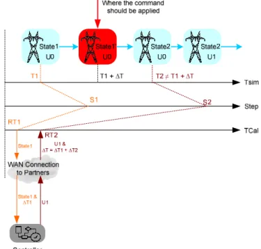
C. Remote coupling PHIL/Cosimulation
In the context of coupling PHIL and co-simulation for multi-laboratory experiments, there are scenarios where the DRTS and offline simulation are geographically separated. In that case, the latency may accumulate and surpass the limita-tion of the time synchronizalimita-tion algorithm (see Fig. 6). More-over, random packet loss due to network congestion outside of a communication network (e.g., LAN) may alter the infor-mation and cause malfunction to the DRTS, as well as any connected hardware.
Fig. 6. Delayed application of command due to unexpected latency.
Therefore, in case of coupling PHIL together with co-simulation in geographically distributed experiments, the time synchronization algorithm must be adapted. The PI compensa-tion has to take into account communicacompensa-tion latency.
IV. DISCUSSION AND OUTLOOK
Two modern ways of modeling and simulating complex cyber-physical energy systems were presented. While co-simulation includes and combines knowledges in various do-mains in order to consider the system in a holistic manner, PHIL provides users with the advantage of replacing error-prone or incomplete models with real-world counterparts and the possibility of scalable testing in faulty and extreme condi-tions. An analysis of these two tools shows that it will make sense to combine the strong points of both approaches to study multi-domain experiments. The advantage is a complementary and joint setup, benefited from realistic behaviors of hardware equipment under a variety of complex environments, co-simulated by several simulators from different domains. The goal is to create a complete and high performance environ-ment to achieve a holistic approach for smart grid validation and roll out.
Major technical challenges have been identified and some solutions were suggested. This contribution gives way for fur-ther proposals in future developments of coupling PHIL and co-simulation.
ACKNOWLEDGEMENT
This work is supported by the European Community's Horizon 2020 Programme (H2020/2014-2020) under project “ERIGrid” (Grant Agreement No. 654113, www.erigrid.eu).
The work of G2Elab and CEA-INES is also partially sup-ported by the Carnot Institute “Energies du Futur” under the PPInterop II project (www.energiesdufutur.eu).
REFERENCES
[1] International Energy Agency, “Smart Grids in Distribution Network - Roadmap development and Implementation,” 2015.
[2] European Network of Transmission System Operators for Electricity, “Research and development roadmap 2013-2022,” 2013.
[3] European Commission, “Energy Roadmap 2050,” Smart Grid Task Force, Brussels, Communication from the commission to the european parliament, the council, the european economic and social committee and the committee of the regions, 2011.
[4] M. Faschang, F. Kupzog, E. Widl, S. Rohjans, and S. Lehnhoff, “Re-quirements for Real-Time Hardware Integration into Cyber-Physical Energy System Simulation,” presented at the Workshop on Modeling and Simulation of Cyber-Physical Energy Systems (MSCPES), Seat-tle, WA, USA, 2015.
[5] M. D. O. Faruque, T. Strasser, G. Lauss, V. Jalili-Marandi, P. Forsyth, and C. Dufour, “Real-Time Simulation Technologies for Power Sys-tems Design, Testing, and Analysis,” IEEE Power Energy Technol.
Syst. J., vol. 2, no. 2, pp. 63–73, Jun. 2015.
[6] G. Lauss, M. D. O. Faruque, K. Schoder, C. Dufour, A. Viehweider, and J. Langston, “Characteristics and Design of Power Hardware-in-the-Loop Simulations for Electrical Power Systems,” IEEE Trans.
Ind. Electron., vol. 63, no. 1, pp. 406–417, Jan. 2016.
[7] K. Mets, J. . Ojea, and C. Develder, “Combining Power and Commu-nication Network Simulation for Cost-Effective Smart Grid Analysis,”
IEEE Commun. Surv. Tutor., vol. 16, no. 3, pp. 1771–1796, Mar.
2014.
[8] S. C. Mueller et al., “Interfacing Power System and ICT Simulators: Challenges, State-of-the-Art, and Case Studies,” IEEE Trans. Smart
Grid, vol. PP, no. 99, pp. 1–1, 2016.
[9] L. Weilin and Z. Xiaobin, “Simulation of the smart grid communica-tions: Challenges, techniques, and future trends,” Comput. Electr.
Eng., vol. 40, no. 1, pp. 270–288, Jan. 2014.
[10] IEEE Computer Society, “IEEE SA - 1516-2010 - IEEE Standard for Modeling and Simulation (M&S) High Level Architecture (HLA)-- Framework and Rules.” 2010.
[11] E. De Jong et al., “European White Book on Real-Time Power Hard-ware in the Loop Testing,” DERlab Report R-005.0, 2012.
[12] W. Ren, M. Steurer, and T. L. Baldwin, “Improve the Stability and the Accuracy of Power Hardware-in-the-Loop Simulation by Selecting Appropriate Interface Algorithms,” in 2007 IEEE/IAS Industrial
Commercial Power Systems Technical Conference, 2007, pp. 1–7.
[13] F. Lehfuss, G. Lauss, P. Kotsampopoulos, N. Hatziargyriou, P. Crolla, and A. Roscoe, “Comparison of multiple power amplification types for power Hardware-in-the-Loop applications,” in 2012 Complexity in
Engineering (COMPENG). Proceedings, 2012, pp. 1–6.
[14] D. Bian, M. Kuzlu, M. Pipattanasomporn, S. Rahman, and Y. Wu, “Real-time co-simulation platform using OPAL-RT and OPNET for analyzing smart grid performance,” in 2015 IEEE Power Energy
Soci-ety General Meeting, 2015, pp. 1–5.
[15] S. Rotger-Griful, S. Chatzivasileiadis, R. H. Jacobsen, E. M. Stewart, J. M. Domingo, and M. Wetter, “Hardware-in-the-Loop co-simulation of distribution Grid for demand response,” in 2016 Power Systems
Computation Conference (PSCC), 2016, pp. 1–7.
[16] B. Palmintier, B. Lundstrom, S. Chakraborty, T. Williams, K. Schnei-der, and D. Chassin, “A Power Hardware-in-the-Loop Platform With Remote Distribution Circuit Cosimulation,” IEEE Trans. Ind.
Elec-tron., vol. 62, no. 4, pp. 2236–2245, Apr. 2015.
[17] R. Liu, M. Mohanpurkar, M. Panwar, R. Hovsapian, A. Srivastava, and S. Suryanarayanan, “Geographically distributed real-time digital simulations using linear prediction,” Int. J. Electr. Power Energy
Syst., vol. 84, pp. 308–317, Jan. 2017.
[18] P. Kotsampopoulos, V. Kleftakis, G. Messinis, and N. Hatziargyriou, “Design, development and operation of a PHIL environment for Dis-tributed Energy Resources,” in IECON 2012 - 38th Annual
Confer-ence on IEEE Industrial Electronics Society, 2012, pp. 4765–4770.
[19] W. Ren et al., “Interfacing Issues in Real-Time Digital Simulators,”
IEEE Trans. Power Deliv., vol. 26, no. 2, pp. 1221–1230, Apr. 2011.
[20] A. J. Roscoe, A. Mackay, G. M. Burt, and J. R. McDonald, “Architec-ture of a Network-in-the-Loop Environment for Characterizing AC Power-System Behavior,” IEEE Trans. Ind. Electron., vol. 57, no. 4, pp. 1245–1253, Apr. 2010.
[21] A. Viehweider, G. Lauss, and L. Felix, “Stabilization of Power Hard-ware-in-the-Loop simulations of electric energy systems,” Simul.
Model. Pract. Theory, vol. 19, no. 7, pp. 1699–1708, Aug. 2011.
[22] V. H. Nguyen, Q. T. Tran, and Y. Besanger, “SCADA as a service approach for interoperability of micro-grid platforms,” Sustain.