Publisher’s version / Version de l'éditeur:
Vous avez des questions? Nous pouvons vous aider. Pour communiquer directement avec un auteur, consultez la
première page de la revue dans laquelle son article a été publié afin de trouver ses coordonnées. Si vous n’arrivez
Questions? Contact the NRC Publications Archive team at
[email protected]. If you wish to email the authors directly, please see the first page of the publication for their contact information.
https://publications-cnrc.canada.ca/fra/droits
L’accès à ce site Web et l’utilisation de son contenu sont assujettis aux conditions présentées dans le site LISEZ CES CONDITIONS ATTENTIVEMENT AVANT D’UTILISER CE SITE WEB.
Research Report (National Research Council of Canada. Institute for Research in
Construction), 2006-03-01
READ THESE TERMS AND CONDITIONS CAREFULLY BEFORE USING THIS WEBSITE. https://nrc-publications.canada.ca/eng/copyright
NRC Publications Archive Record / Notice des Archives des publications du CNRC : https://nrc-publications.canada.ca/eng/view/object/?id=6ff33ad9-2d98-4438-87e2-fa386d61cdb0 https://publications-cnrc.canada.ca/fra/voir/objet/?id=6ff33ad9-2d98-4438-87e2-fa386d61cdb0
NRC Publications Archive
Archives des publications du CNRC
For the publisher’s version, please access the DOI link below./ Pour consulter la version de l’éditeur, utilisez le lien DOI ci-dessous.
https://doi.org/10.4224/20377048
Access and use of this website and the material on it are subject to the Terms and Conditions set forth at
Guide for Sound Insulation in Wood Frame Construction
Preamble and Acknowledgement
This Guide addresses flanking transmission of sound through wood framed construction. Continuous structural elements and connections at the junctions of partition walls and floors provide transmission paths that by-pass the separating partition between two noise-sensitive spaces.
Flanking transmission is sound transmission between two rooms by paths other
than directly through the nominally separating wall or floor assembly. Flanking exists in all buildings and its importance in determining the apparent sound insulation (that perceived by the occupants) depends on of the construction details of the walls, the floors and their junctions.
This Guide is the derivative of four industry-sponsored research projects conducted at IRC/NRC. The focus and construction details were decided by a Steering Committee of technical representatives from each of the supporting partners. Partners included Canada Mortgage and Housing Corporation, Forintek Canada Corporation, Marriott International, National Research Council Canada, Owens Corning, Trus Joist, and USG.
This Guide supersedes the version published in 2005. This version includes estimates of the flanking due to directly attached gypsum board on ceilings, corridor walls, and exterior walls. (The first version assumed that these surfaces were mounted on resilient channels, and thus had negligible effect.)
Overview of Content and Intended Application
The intent of this guide is to present the findings from a substantial experimental research study, in a form that can be used as a framework for design. The guide focuses on wood-framed assemblies because that was the priority of the study on which it is based. Other types of walls and floors with concrete or steel structural assemblies also have significant reduction of sound isolation due to flanking, but they are outside the scope of this guide.
The experimental study included only a limited set of constructions. Specific constraints imposed on the research specimens are discussed further in the section on performance of typical assemblies. Many materials and many construction details were kept constant, to avoid masking the effect of the systematic modifications. As a result, clear and consistent trends could be associated with specific construction changes, but it must be recognized that the results may not capture the effect of all significant variants.
To show trends clearly, and to provide a framework for design estimates,
expected sound transmission ratings are presented for each construction. For a number of specific cases, detail drawings and specifications including
identification of specific proprietary materials are presented, and these are documented further in a detailed report [1]. Although it is not repeated at every step of this guide, it should be understood that some variation is to be expected in practice due to changing specific design details, or poor workmanship, or substitution of “generic equivalents”, or simply rebuilding the construction. Despite this caveat, the authors believe that trends shown here do provide a good estimate of the flanking in typical wood-framed constructions.
Organization of this Guide
After a brief presentation of the basic concepts for transmission of flanking sound in buildings, and a general design approach, this Guide divides into two main parts focusing in more detail on transmission of sound from airborne sources, and impact sound from footsteps.
Basic Concepts ... 3
Basic Concepts for Airborne Sound Sources ... 4
Basic Concepts for Impact Sound Sources ... 6
Basic Concepts for Impact Transmission on Joist Floors ... 8
Design Approach ... 9
Step 1 – Select possible partitions ... 10
Step 2 – Establish basic framing details... 10
Step 2a – Horizontally separated rooms... 11
Step 2b – Vertically separated rooms ... 12
Step 2c – Diagonally separated rooms ... 13
Step 3 – Optimize surface treatments ... 14
Step 4 – Establish the topping and floor covering ... 15
Sound from Airborne Sources... 16
Vertical Flanking in Basic Wood-framed Constructions (One apartment above the other, airborne sound source) ... 18
Changes to Control Vertical Flanking between Apartments (One apartment above another, Airborne Sound Source) ... 23
Table of Change in Vertical Flanking due to Toppings ... 24
Horizontal Flanking in Wood-framed Constructions One apartment beside the other, airborne sound source)... 25
Changes to Control Horizontal Flanking (One apartment beside another, Airborne Sound Source) ... 34
Flanking between Row Housing Units (Side-by-side Row Housing, Airborne Sound Source) ... 41
Sound from Impact Sources ... 46
Vertical Flanking in Basic Wood-framed Constructions (One apartment above the other, Impact sound source)... 48
Estimating Apparent-IIC for Combined Paths (Vertical Transmission) .. 50
Table of Typical Vertical Flanking (Impact)... 51
Changes to Control Vertical Flanking (One apartment above another, Impact sound source) ... 53
Table of Change in Vertical Flanking due to Toppings (Impact) ... 54
Horizontal Flanking in Wood-framed Constructions (One apartment beside the other, Impact sound source) ... 56
Changes to Control Horizontal Flanking (One apartment beside another, Impact sound source) ... 65
Flanking between Row Housing Units (Side-by-side Row Housing, Impact Sound Source)... 72
Appendix – Construction drawings... 76
Basic Concepts
Basic Concepts for Structure-borne Transmission of Sound
Because all types of construction have some transmission of structure-borne vibration, the sound isolation between rooms in buildings is systematically less than the sound transmission class (STC) for the separating wall or floor.
This section introduces the basic concepts for describing structure-borne sound, and explains the terminology.
For adjacent rooms in a building, the sound isolation is often much less than would be expected from the rated STC of the separating wall or floor.
This happens because, in addition to direct transmission through the separating construction (which is what the STC indicates), the sound causes structure-borne vibration in all surfaces of the source room. Some of this vibration is transmitted across the surfaces (walls, floors or ceiling), through the junctions where these surfaces connect, and is radiated as sound into the receiving room.
he following diagrams show transmission at the floor/wall junction, in more s
e most important paths for this structure-borne of Transmission via floor surfaces Transmission via ceiling surfaces Sound
source
Transmissionthrough wallTransmission via floor surfaces Transmission via
ceiling surfaces Sound
source
Transmissionthrough wallT
detail. Vibration can be transmitted via many paths, but in practice a few path transmit most of the energy.
In wood-framed construction, th
transmission usually involve the wall/floor junction, so this is the focus for most the following discussion.
Basic Concepts for Airborne Sound Sources
Sound in a room may come from many sources – someone talking, or the loudspeakers of a TV or stereo sound system. In the following drawings a red loudspeaker is used to indicate such sound sources, referred to as airborne sound sources.
The following section deals with the transmission of impact noise due to footsteps.
Some of the sound energy may be transmitted directly across the wall and floor assemblies and some via the floor/wall junction, as indicated by the arrows. In addition to the Direct Transmission through the separating wall (the STC for the wall describes this), there are other paths involving structure-borne transmission across the floor and wall surfaces, which acoustical standards call “Flanking Transmission” because they transmit vibration around the partition nominally separating the two rooms.
Direct Transmission Flanking paths via other surfaces
Apparent Transmission Direct
Transmission Flanking paths via other surfaces
Apparent Transmission Apparent Transmission
The Apparent Transmission includes both the Direct Transmission through the wall and the additional energy transmitted by Flanking Transmission via structure-borne paths, so the resulting Apparent-STC is lower than the STC rating for direct transmission through the wall.
From the occupants’ perspective, all that matters is the overall sound isolation between the adjacent spaces, including the effect of all transmission paths. For airborne sound, the Apparent-STC provides a standardized estimate of this sound isolation.
For sound transmission between rooms separated by a floor, flanking
transmission tends to reduce the Apparent-STC relative to the value for direct transmission through the floor assembly. As indicated by the arrows, there are generally a number of structure-borne flanking transmission paths in addition to direct transmission through the separating floor assembly.
Direct Transmission Apparent Transmission Flanking Path Transmission Direct Transmission Apparent Transmission Flanking Path Transmission
Which paths are most significant depends on details of the wall and floor
assemblies. Discussion of typical constructions later in this guide will show only the most important paths, but it should be remembered that changing some of the details could add other significant paths that reduce the overall sound isolation.
Whether for transmission from the room above to the room below, or vice versa, the Apparent-STC is the same (and the same transmission paths are important) for airborne sound.
Summary – Basic Concepts for Airborne Sources
Because all types of construction have some flanking transmission, the Apparent-STC between rooms in buildings is systematically less than the STC for the separating wall or floor.
Flanking significantly reduces the apparent sound isolation for some constructions, but it can be systematically controlled.
Basic Concepts for Impact Sound Sources
The impact noise of primary concern is that due to footsteps. In the following drawings a small person is used to represent impact sound sources. This figure is sized to fit on the drawings; in the later drawings, scaling considerations would suggest a very small person, which is quite suitable because young children running and jumping pose some of the most severe tests of impact insulation for lightweight wood framed construction.
The preceding section deals with the parallel problem of controlling noise from airborne sound sources such as someone talking, or the loudspeakers of a TV or stereo sound system.
Flanking via other surfaces Apparent Transmission Direct Transmission Flanking via other surfaces Apparent Transmission Direct Transmission
As indicated by the arrows, some of the impact sound energy may be transmitted directly through the floor assemblies (the laboratory impact insulation class (IIC) for the floor rates this) and some is structure-borne transmission (flanking) across the floor assembly and via the floor/wall junction into attached surfaces that radiate the sound. From the occupants’ perspective, all that matters is the overall sound insulation between the adjacent spaces, including the effect of all transmission paths.
When the receiving room is below the impact source, the Apparent Transmission includes both the Direct Transmission through the floor and the additional
Flanking Transmission via structure-borne paths, so the resulting Apparent-IIC1 tends to be lower than the IIC rating for direct transmission.
1
For consistency with terminology in the section on airborne sources, the term “Apparent Impact Insulation Class (Apparent-IIC)” is used here. The pertinent ASTM standard (E1007-04) calls this quantity Field Impact Insulation Class, but only applies to the case of vertical transmission.
For side-by side rooms, flanking may also cause serious impact sound transmission, despite the absence of direct transmission. As indicated by the arrows, there are generally a number of structure-borne flanking transmission paths.
• Only flanking transmission
• All paths involve the
floor surfaces
• Only flanking transmission
• All paths start from
floor surface
• Only flanking transmission
• All paths involve the
floor surfaces
• Only flanking transmission
• All paths start from
floor surface
Which transmission paths are most significant depends on details of the wall and floor assemblies. Discussion of typical constructions later in this guide will show only the most important paths, but it should be remembered that changing some of the details could add other significant paths that reduce the overall sound insulation.
Note that vibration transmitted across the floor can be radiated from several surfaces both in the room horizontally adjacent and on the diagonal.
Summary – Basic Concepts for Impact Sources
Flanking transmission of impact sound is a concern both for rooms beside and below the one where footsteps are creating impact sound.
Because all types of construction have some flanking transmission, the Apparent-IIC to the room below is systematically less than the IIC for the separating floor.
Flanking significantly reduces the apparent sound insulation for some constructions, but it can be systematically controlled.
Basic Concepts for Impact Transmission on Joist Floors
For lightweight wood framed construction, the transmission of structure-borne sound is quite complicated, because several factors can change the strength of the transmitted footstep sound.
One obvious factor is the floor surface. Toppings that increase surface weight reduce impact sound at low frequencies, but hard surfaces increase the high frequency sound. Adding flooring such as carpet over the basic floor assembly gives a softer surface that reduces the impact energy injected into the underlying floor, especially for high frequencies.
Direct Transmission Flanking Transmission Flanking Transmission Flooring (carpet, etc.) Flanking Transmission Direct Transmission Flanking Transmission Flanking Transmission Flooring (carpet, etc.) Flanking Transmission
Some of the impact energy is transmitted as structure-borne vibration across the floor assembly and via the floor/wall junction into attached surfaces that radiate the flanking sound into adjacent rooms, as indicated by the arrows.
For lightweight joist floors, the vibration energy at the point of impact is not the same as at floor/wall junction because vibration energy is reduced as it
propagates across the floor. There is a greater vibration reduction perpendicular to the joists than in the direction parallel to the joists, and adding a topping to the floor changes this reduction.
Summary – Concepts for Impact Sound on Joist Floors
The strength of the structure-borne impact sound reaching adjacent rooms depends on:
• the floor surface,
• the direction of floor joists relative to the floor/wall junction, • how far the impact source is from the floor/wall junction.
Design Approach
This section begins with a brief listing of some important findings for flanking involving the wall/floor junction that may influence the sound insulation achieved by a wood frame building.
Key Factors for Flanking:
Except where required for wind and seismic loads, building elements (such as OSB, gypsum board, joists, etc.) should not be continuous across or under a partition because they can introduce strong flanking paths.
Whether the room pairs are separated by a partition floor or a wall, unless the floor has a massive and resiliently isolated topping, the dominant flanking path typically involves the top surface of the floor and the flanking junction formed by intersection of the wall and floor. One of the most important factors in determining the magnitude of the floor flanking path(s) is joist orientation (parallel versus perpendicular to the flanking junction).
In comparison to the effects associated with continuity and joist orientation, other details (junction blocking details at the wall/floor junction, solid lumber versus wood-I joists, oriented strand board versus plywood subfloor) were not particularly important. Wall type (single versus double stud) was important for horizontally (side-by-side) and diagonally separated rooms, but not as important for one room above the other.
Flanking paths involving the floor can be significantly suppressed by adding a floor topping, but joist orientation remains a factor because the effectiveness of a topping depends on the floor to which it is applied. In general, a topping affects airborne and impact sources differently, and affects direct and flanking transmission paths differently:
> For airborne sound insulation, the most important factor is the mass of the applied topping. Topping installation (bonded, placed, or floating on a resilient material) is also significant but less important.
> For impact sound insulation, there are three important factors – topping mass, topping installation and, hardness of the exposed topping surface. A significant increase in mass is required to improve low frequency impact sound insulation. Resilient support of a topping tends to improve performance. A hard subfloor or topping surface (such as concrete) tends to worsen impact noise and lower the (Apparent-)IIC, but addition of a floor covering tends to mask this in practice
Floor coverings can significantly improve the apparent impact sound
insulation when the floor covering reduces the hardness of the floor surface. Thus, carpet will be more effective than vinyl and both tend to be more effective when applied over hard concrete or gypsum concrete surfaces than over comparatively soft surfaces like OSB.
Flanking paths involving gypsum board surfaces can be significantly suppressed by mounting the gypsum board on resilient channels. Adding resilient channels is more effective than directly attaching another layer of
The preceding observations are limited to constructions examined in the supporting study [1] and are not necessarily applicable to an arbitrary
construction, so the results should be used with care. However, they should be sufficient to identify the most important parameters when considering the acoustical design of a wood frame construction for noise sources other than plumbing or HVAC.
It should also be noted that there are factors such as room dimension (which determines the relative length of the junctions), and typical location for impact sources, that cannot be adequately addressed in a simple design approach like that presented here. Such factors may be important, but their effect can only be estimated using a more detailed calculation.
The following discussion assumes that the use for the rooms – and hence the apparent airborne and impact sound insulation needed between them – has been chosen.
There are basically four steps in the design approach. However, several iterations may be required to arrive at a design that satisfies requirements for sound insulation, fire resistance and structural integrity.
Step 1 – Select possible partitions
Possible partitions (wall and floor assemblies) must have a direct sound
insulation rating (STC, and IIC if relevant) that is at least as great as the required apparent sound insulation between rooms.
Step 2 – Establish basic framing details
While basic framing details typically will not change which flanking path is dominant for a particular junction, they can change the magnitude of flanking transmission. Thus, the next step is to take the wall and floor assemblies chosen in Step 1, and to decide the configuration that will minimise flanking transmission and hence provide the greatest apparent sound insulation.
The tables below provide a listing of the factors and their effect on the dominant flanking path for horizontally, vertically, and diagonally separated rooms.
Because results from the supporting study indicated that flanking is most severe for horizontally separated rooms, the design should begin by considering design details for horizontally separated rooms.
Step 2a – Horizontally separated rooms
The dominant flanking path for this room pair is from the floor in one room to the floor in the other. Other paths (floor-wall and wall-floor) are relatively unimportant except when a floor topping is applied.
Particular attention should be paid to floor and wall details that will affect transmission from one floor to the other.
The table indicates that – with or without a topping – the preferred joist
orientation is parallel to the flanking junction when the partition wall is single stud construction. However, if the partition wall is double stud construction the
preferred joist orientation is perpendicular, if there is no topping. (There are no data to indicate the trend when the partition wall is double stud and there is a topping).
Horizontally Separated
Rooms
Flanking paths via other surfaces
Wall Type (double stud best) 2 Floor Element and Choices
Single Stud Double Stud Orientation Parallel better than
Perpendicular
Perpendicular better than Parallel
Continuity Avoid3 Avoid
Joist
Wood-I vs Lumber Minimal difference Minimal difference
Continuity Minimal difference Discontinuous much better
Subfloor
OSB vs plywood Minimal difference Minimal difference
OSB overlay Improvement Improvement
Bonded concrete Improves more Improves more
Topping
Floating concrete Improves most Improves most
It is recognised that the preferred joist orientation cannot be used at the junction with all noise sensitive spaces, so the preferred joist orientation should be reserved for the junction between those of greatest concern.
2
When the rooms are horizontally separated by a partition wall, there is less flanking involving the subfloor when the wall is of double stud construction
Step 2b – Vertically separated rooms
The dominant flanking path is from the floor in the room above to the wall(s) in the room below when the gypsum board ceiling is mounted on resilient channels. Other paths (wall-wall and wall-ceiling) are relatively unimportant except when a very effective floor topping is applied.
For vertically separated rooms, there will typically be four wall floor junctions contributing to the flanking transmission. This paradoxically makes the design process simpler. If the same wall type is used at each junction, then there is no advantage to a particular joist orientation, because the joists are parallel to two junctions and perpendicular to the other two.
Vertically Separated
Rooms
Flanking Path Transmission Wall Type (minimal difference)4 Floor Element and ChoicesSingle Stud Double Stud Orientation Parallel better than
Perpendicular
Perpendicular better than Parallel
Continuity N/A N/A
Joist
Wood-I vs Lumber Minimal difference Minimal difference
Continuity N/A N/A
Subfloor
OSB vs plywood Minimal difference Minimal difference
OSB overlay Improvement Improvement
Bonded concrete Improves more Improves more
Topping
Floating concrete Improves most Improves most
The table suggests the only major advantage that can be gained from framing orientation occurs if two opposite walls are single stud and two are double stud, and joists are oriented parallel to the former (and hence perpendicular to the latter).
4
When the rooms are vertically separated by a partition floor, the flanking involving the subfloor is not particularly sensitive to the type of wall
Step 2c – Diagonally separated rooms
The dominant flanking path is from the floor in the room above to the wall(s) in the room diagonally below when the gypsum board ceiling is mounted on resilient channels. However, when the gypsum board ceiling is fastened directly to the joists then the dominant path involves the ceiling.
For diagonally separated rooms,
Diagonally Separated
Rooms
Flanking paths via room surfaces
Flanking paths via room surfaces
Wall Type (double stud best)5 Floor Element and Choices
Single Stud Double Stud Orientation Parallel better than
Perpendicular
Perpendicular better than Parallel
Continuity Avoid6 Avoid
Joist
Wood-I vs Lumber Minimal difference Minimal difference
Continuity Minimal difference Discontinuous much better
Subfloor
OSB vs plywood Minimal difference Minimal difference
Resilient vs Direct mounting Very significant difference Very significant difference Ceiling
Layers 1 vs 2 Small difference Small difference
OSB overlay Improvement Improvement
Bonded concrete Improves more Improves more
Topping
Floating concrete Improves most Improves most
The table suggests that the most effective approach would be to treat the ceiling of the receiving room by mounting the gypsum board on resilient channels. However, a floor topping in the source room will treat both horizontal and diagonal flanking paths.
5
When the rooms are horizontally separated by a partition wall, there is less flanking involving the subfloor when the wall is of double stud construction
Step 3 – Decide on gypsum board treatments
As a general rule, the gypsum board of a wall should not be continuous across the end of a partition.
Locate extra surface layers where they provide most benefit. Increase the weight of direct attached gypsum board surfaces expected to involve a significant flanking path, or resiliently mount the gypsum board.
Whether it is necessary to resiliently mount the gypsum board of a sidewall depends on the design target for sound insulation.
> For horizontally separated rooms, a resilient mounting should be used when the desired Apparent-STC exceeds 55.
> For diagonally separated rooms, a resilient mounting should be used when the desired Apparent-STC exceeds 60.
> For vertically separated rooms, consider both the number of layers and location of resilient channels, because all surfaces of the supporting walls are potential flanking paths for airborne and impact sound.
An example for vertical transmission is given to illustrate the point.
The example has a single stud wall with resilient channels on one side of the partition wall, in apartment construction. The dominant vertical flanking path involves the supporting wall(s) below, and the same wall(s) must adequately suppress direct transmission between horizontally separated rooms. As shown in the sketches, layers of gypsum board should be placed to maximize the number of direct attached layers, while meeting the sound insulation and fire resistance requirements for the wall.
Apparent STC 52
with four flanking walls Apparent STC 50
with four flanking walls
Direct STC 55 plus flanking Direct STC 55 plus
flanking DirectSTC 55DirectSTC 55 flankingflankingplus plus
Better for Flanking
Two layers on flanking surface
Worse for Flanking
One layer on flanking surface
Best for Flanking:
Mounting the gypsum board on both sides of the wall on resilient channels minimises flanking for all paths, but requirements for racking resistance of the wall may prevent this.
Vertical insulation between the rooms to the right of the wall should approach the direct STC of 55 in all cases, because the resilient channels on the walls reduce flanking to an insignificant amount.
Adding more layers of material is effective only if they are properly positioned. In general, it is most effective to increase the mass of the subfloor, which attenuates all the flanking paths (vertical and horizontal) as well as the direct path for vertical transmission.
The final task is to estimate the apparent airborne and apparent impact sound insulation and determine whether the chosen joist orientation and basic wall type will meet the design goals.
If the apparent airborne or impact sound insulation is deficient, then Steps 1 to 3 must be repeated with some changes, or one must accept that a topping will be required and go to Step 4.
Step 4 – Establish the topping and floor covering
Because the dominant flanking path involves the floor for both horizontally and vertically separated rooms, a floor topping can be a very effective treatment to make-up for any deficiencies remaining after Step 3.
Tables of changes in apparent airborne and changes in apparent impact sound insulation for specific toppings can be used to select a possible topping. Using softer floor covering (carpet instead of vinyl) in the source room can be used to improve the impact sound insulation, but this will not significantly improve the airborne sound insulation because these coverings are relatively lightweight.
Sound from Airborne Sources
This section gives information on flanking transmission for some common wood-frame constructions. It deals with sound transmission from airborne sound sources such as loudspeakers or people speaking. A similar section on Impact Sound Transmission presents the corresponding cases with noise from footsteps.
This section is divided into three parts, considering the apparent sound transmission between two adjacent occupancies that are:
1. one apartment above another (separated by a floor) 2. one apartment beside another (separated by a wall)
3. side-by-side “row housing” (multiple stories with no requirement for sound insulation between stories) where the gypsum board of the ceiling is applied directly to the bottom of the floor joists.
As noted in the introduction, the experimental study included only a limited set of constructions, all of them wood-framed with wood-I (or dimensional) joists 406 mm on centre, and a subfloor surface of 19 mm OSB or plywood. Other specific constraints on the research specimens included the following:
• Two ceiling options were evaluated. For “apartments”, the ceilings had 2 layers of 15.9 mm fire-rated gypsum board, installed on resilient metal channels, spaced 406 mm on centre. For “row housing” (multiple stories with no requirement for sound insulation between stories) the ceiling of single-layer 12.7 mm regular gypsum board was applied directly to the bottom of the floor joists.
• Wall-wall paths were evaluated for a subset of the constructions with one or two layers of gypsum board either screwed directly to the studs or mounted on resilient metal channels:
> For horizontally separated rooms sharing a common sidewall (exterior wall or corridor wall), transmission via the wall-wall path was insignificant when the gypsum board was mounted on resilient channels. However, when the gypsum board was screwed directly to the sidewall studs, Apparent-STC due to the wall-wall path was 54 to 58, depending on junction details and the number of layers. The wall-wall path for horizontally separated rooms is considered in this Guide.
> For vertically separated rooms (one above the other), transmission via the wall-wall path was insignificant when the gypsum board was mounted on resilient channels. With directly attached gypsum board the Flanking-STC was consistently over 60. This Guide ignores such wall-wall paths.
> For diagonally separated rooms sharing a common sidewall (exterior or corridor wall), transmission via the wall-wall path was insignificant when the gypsum board was either directly attached or resiliently mounted to the studs.
Many of the materials were specific proprietary products, which are identified in individual assembly specifications. It should be understood that significant variations must be expected if “generic equivalents” are incorrectly chosen, or details are changed.
An earlier NRC study [2] showed a range of 5 in STC values among a set of floor assemblies when all materials and component dimensions were consistent, except that the wood-I joists were from different manufacturers. Presumably, joist depth is insufficient to establish “equivalence” because of differences in
materials, flange dimensions, etc. Thus, large variations can be expected when the basis of deciding “equivalence” does not completely define the vibration and acoustic performance. While the variation due to other construction materials like gypsum board, fibrous batt insulation, has been much smaller, the example highlights the magnitude of possible errors due to assessing “generic
equivalence” on an inappropriate physical property.
It must also be recognized that the values given in this Guide are design
estimates representative of typical constructions using the construction materials indicated. Variation in sound transmission for wood frame wall and floors is significant [1] and it must be realized that individual values for “exactly replicated” constructions may differ from those indicated in this Guide. Any deviation will be a function of the exact construction, but Apparent-STC or Apparent-IIC changes of two, or more, should not be surprising.
Complete construction details are included at the end of this Guide so that the assemblies can be replicated exactly, or detailed technical information can be obtained from the manufacturer to refine selection of “generic equivalents”.
Vertical Flanking in Basic Wood-framed Constructions
(One apartment above the other, airborne sound source)
For the case of two apartments verticallyseparated by a floor/ceiling assembly, there are two key issues:
1. The main flanking path is consistently from the subfloor of the room above to the walls of the room below or vice versa, if the floor surface is a layer of oriented strand board (OSB) or of plywood directly fastened to the top of the floor joists.
2. Reduction of Apparent-STC by flanking depends on the flanking transmission via all walls of the room below. Airborne Sound Source Direct Transmission through floor Airborne Sound Source Airborne Sound Source Direct Transmission through floor Airborne Sound Source Direct Transmission through floor Airborne Sound Source
The discussion starts with flanking via just one wall (to explain relative significance of specific aspects of the constructions), and then shows the combined effect of flanking via all wall surfaces in the room below.
Sound transmission paths are shown in the figure below, for the case where floor joists are parallel to the flanking wall and that wall has double wood stud framing. The dominant flanking path is via the subfloor of the room above and wall of the room below.
plus flanking
Apparent STC 54 with one flanking wall
Direct STC 55
Floor joists parallel to flanking wall
(non-loadbearing wall)
plus flanking
Apparent STC 54 with one flanking wall
Direct STC 55 Direct STC 55
Floor joists parallel to flanking wall
(non-loadbearing wall)
The STC of 55 for direct sound transmission through the floor/ceiling system would be good enough to satisfy most occupants most of the time. The
Apparent-STC was 1 or 2 lower than Direct-STC in all cases studied, even including only the flanking by one wall.
Changes in the construction can alter the flanking transmission and hence the Apparent-STC, and a number of specific variants are listed in the table below, with their typical effect.
Change in Construction
Typical Effect due to one flanking wall
Resulting Apparent-STC Changing Floor Materials
OSB subfloor ⇒ plywood, or dimensional wood floor joists ⇒ wood-I joists not significant 53-55 Changing Framing of floors, or of walls, or of floor/wall junction may be significant
(see next case) 53-55
Changing Walls Below
On walls below, 1 layer ⇒ 2 layers of gypsum board
less flanking 54-55
On walls below, mount gypsum
board on resilient metal channels negligible flanking 55
Note 1: Apparent-STC values in this table include only the direct transmission via the floor (STC 55) and flanking via one wall – how to include flanking via all significant walls of the room below is explained later.
Note 2: All cases shown in the table above assume a floor assembly with 19 mm OSB subfloor attached over joists spaced 400 mm on centre, and a ceiling with two layers of fire-rated gypsum board supported on resilient metal channels, spaced 400 mm apart (typical STC=55 for direct transmission). With changes to the floor/ceiling system, the direct transmission through the ceiling and hence the significance of the flanking could change appreciably, as illustrated in the next table.
In practice, the Apparent-STC may vary depending on the specific products used and the details of installation as noted above, but this table (like similar tables in later sections) shows explicit values to clarify the trends to be expected with the listed individual changes.
Changing the orientation of the floor joists relative to the wall of concern (from parallel to the wall to perpendicular to the wall), or changing the wall framing from double row of studs to single studs or to staggered studs with a common plate, or changing the construction at the floor/wall junction all have some effect on the flanking transmission from the upper room to the one below, or vice versa. Most of these changes in vertical flanking transmission due to framing variations are small enough so they can be ignored in practice.
There seems to be slightly more vertical flanking when the floor joists are perpendicular to the wall (i.e., for a load-bearing wall) than when joists are parallel. However, the difference is small and floor joists are normally parallel to some walls in the room below and perpendicular to others, so an average value can be used with reasonable confidence.
Vertical flanking has been found to be significantly worse only for the case with a shear wall where the joists are parallel to the wall and the plates at top/bottom of the wall framing are directly connected to the subfloor, as illustrated below.
Floor joists parallel to flanking shearwall (non-loadbearing wall)
plus flanking
Apparent STC 53 with one flanking wall
Direct STC 55
Floor joists parallel to flanking shearwall (non-loadbearing wall) plus flanking Apparent STC 53 with one Direct STC 55 Direct STC 55 flanking wall
In this case, the Apparent-STC of 53 was consistently lower than for other cases tested. Hence this case is treated differently in the following table showing the combined effect of flanking paths via all the significant walls in the room below.
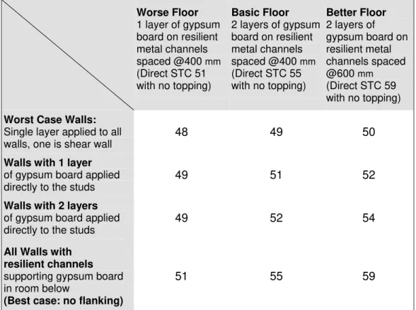
Table of Typical Vertical Flanking (basic floor)
The following table gives Apparent-STC due to the combined effect of direct transmission through the basic floor/ceiling, plus total flanking transmission via four walls of the room below, for four specific cases.
Worse Floor 1 layer of gypsum board on resilient metal channels spaced @400 mm (Direct STC 51 with no topping) Basic Floor 2 layers of gypsum board on resilient metal channels spaced @400 mm (Direct STC 55 with no topping) Better Floor 2 layers of gypsum board on resilient metal channels spaced @600 mm (Direct STC 59 with no topping)
Worst Case Walls:
Single layer applied to all walls, one is shear wall
48 49 50
Walls with 1 layer
of gypsum board applied directly to the studs
49 51 52
Walls with 2 layers
of gypsum board applied directly to the studs
49 52 54
All Walls with resilient channels
supporting gypsum board in room below
(Best case: no flanking)
51 55 59
Note1: This table presents Apparent-STC expected with a basic OSB or plywood subfloor. The corresponding Table of Change in Vertical Flanking due to Toppings gives the effect of modifying the floor surface.
Note2: Results will be about the same for one or two layers of resiliently mounting the gypsum board because in either case flanking paths do not contribute significantly relative to the direct path.
For intermediate situations where walls are a mix of these cases, a weighted linear average should be used. For example, when the gypsum board of one wall in the lower room is on resilient channels, two walls have 2 layers directly attached to the studs, and the fourth wall has a single layer directly attached gypsum board, the weighted linear average of the values for the “Better Floor” would be [(59+2x54+52)/4], giving Apparent-STC 55.
The Apparent-STC expected due to all paths was calculated from the best estimates for direct transmission plus flanking paths for all significant walls in the room below. The latter were based on an average of the flanking transmission with floor joists parallel or perpendicular to the wall, for single stud or double stud walls. As noted above, the difference among these configurations is small and floor joists are normally parallel to some walls in the room below and
perpendicular to others, so an average value can be used with reasonable confidence.
Summary – Vertical Flanking in Typical Constructions
For the case of two apartments vertically separated by a floor/ceiling
assembly, the Apparent-STC between the two occupancies is systematically less than the STC for direct transmission through the separating floor.
There are three main issues:
1. The main flanking path is
consistently from the subfloor of the room above to the walls of the room below or vice versa, if the subfloor is a layer of oriented strand board (OSB) or of plywood directly
fastened to the top of the floor joists. 2. Some changes in the wall below can
significantly reduce transmission via a specific wall surface. Adding a second layer of gypsum board reduces flanking. Mounting gypsum board on resilient channels should reduce flanking to insignificance for most practical floor assemblies. 3. Reduction of Apparent-STC by
flanking depends on the flanking transmission via all walls of the room below. Airborne Sound Source Direct Transmission through floor Airborne Sound Source Airborne Sound Source Direct Transmission through floor Airborne Sound Source Direct Transmission through floor Airborne Sound Source
As discussed in the detailed report [1], the estimates in this section should be applied only for cases where wall and floor details are within the range of the tested specimens (links to specifications are in section on Changes to Control Horizontal Flanking)
This Guide ignores the vertical sound transmission between stories within a single occupancy where the gypsum board ceiling is screwed directly to the floor joists (called “row housing” in later sections)
Changes to Control Vertical Flanking between Apartments (One apartment above another, Airborne Sound Source)
For the case of two apartments vertically separated by a floor/ceiling assembly (vertical transmission):
1. Changes to control flanking must be focused on the elements of the dominant flanking path.
2. The two surfaces that can be modified to reduce flanking transmission are the walls in the room below, and the floor surface in the room above.
3. Effects of some common changes are presented in this section
Airborne Sound Source Direct Transmission through floor Airborne Sound Source Airborne Sound Source Direct Transmission through floor Airborne Sound Source Direct Transmission through floor Airborne Sound Source
The effects of simple changes to the walls of the room below are presented in detail in the earlier section on flanking in typical basic constructions. The combined flanking transmission via all walls of the room below must be considered. Typical Apparent-STC values are listed in the Table of Typical Vertical Flanking
• The worst case is with a single layer of gypsum board directly attached to the studs of all the walls below.
• Adding a second layer of directly attached gypsum board provides slight reduction in the flanking transmission.
• If the gypsum board is mounted on resilient metal channels, the flanking via that surface is reduced enough so that it can be ignored. Any such walls need not be included as significant when assessing flanking transmission.
Note that resilient channels must be mounted between the studs and the gypsum board, not between two layers of gypsum board.
In addition to the effect of specific gypsum board treatment of the walls in the room below, the Apparent-STC can also be improved by changing the floor surface.
• Adding a topping over a basic plywood or OSB subfloor gives more attenuation both for direct transmission through the floor and for the dominant flanking transmission paths.
• The change in flanking due to adding a topping depends on the type of topping and on the orientation of the floor joists relative to the flanking wall. However, an average value can be used as a slightly conservative design estimate because the floor joists are normally parallel to some walls in the room below and perpendicular to others.
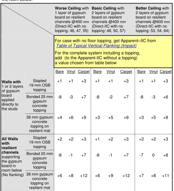
Table of Change in Vertical Flanking due to Toppings
The following Table shows the change in Apparent-STC expected from adding a topping, including both direct transmission through the floor/ceiling and flanking transmission via the walls of the room below.
Worse Ceiling 1 layer of gypsum board on resilient metal channels @400mm (Direct STC 51 with no topping) Basic Ceiling 2 layers of gypsum board on resilient metal channels @400mm (Direct STC 55 with no topping) Better Ceiling 2 layers of gypsum board on resilient metal channels @600 mm (Direct STC 59 with no topping) Walls in room below Floor Topping
For case with no floor topping, get Apparent-STC from the Table of Typical Vertical Flanking
For the complete system including a topping, add (to the Apparent-STC without a topping) a value chosen from table below
Stapled 19 mm OSB topping +5 +6 +7 Bonded 25 mm gypsum concrete topping +10 +9 +9 All Walls with
1 or 2 layers of gypsum board applied directly to the studs in room below 38 mm gypsum concrete topping on resilient mat +14 +13 +12 Stapled 19 mm OSB topping +4 +5 +5 Bonded 25 mm gypsum concrete topping +11 +11 +11 All Walls with resilient channels supporting gypsum board in room below (No flanking) 38 mm gypsum concrete topping on resilient mat +15 +15 +15
Note1: Specifications and detail drawings for the basic assemblies and added toppings are given in the following section on Changes to Control Horizontal Flanking. Values in this table were obtained from evaluation of a limited set of specimens built with specific products that are identified in the detailed descriptions. Using “generic equivalents” may change results.
Note2: Results will be about the same for one or two layers of resiliently mounting the gypsum board because in either case flanking paths do not contribute significantly relative to the direct path.
Horizontal Flanking in Wood-framed Constructions
One apartment beside the other, airborne sound source)
For the case of two apartments horizontally separated by a partition wall assembly, there are two key issues:Transmission via floor surfaces (Ceiling surfaces isolated)
Transmission through wall Airborne Sound Source Transmission via floor surfaces (Ceiling surfaces isolated)
Transmission through wall Airborne
Sound Source
1. The main flanking path is consistently from the floor of one room to the floor of the room beside, if the subfloor is a continuous layer of oriented strand board (OSB) or of plywood directly fastened to the top of the floor joists.
2. Reduction of Apparent-STC may be affected by details of the floor assembly, the wall assembly, and the continuity of structural elements across the floor/wall junction.
Note that the above assumes that other horizontal paths (wall-wall and ceiling-ceiling paths) are not significant. This will be the case if there are resilient channels or other vibration breaks in such paths.
Several “row housing” cases, where the ceiling is not on resilient channels, are presented in a later section; with a basic subfloor, they exhibit very similar horizontal flanking to the cases in this section.
To highlight the key factors influencing horizontal flanking across floor/wall junctions, a number of typical configurations are presented, proceeding from cases where the flanking effect is rather small to cases where flanking drastically reduces the sound isolation.
With the subfloor continuous across the junction at a double stud wall, Apparent-STC is appreciably below the Apparent-STC 55 for direct transmission through the
separating wall.
Link to Corresponding Impact
Apparent
STC
50 to 51
Flanking
via subfloor
Direct
Transmission
STC 55
Floor joists
perpendicular to
separating wall
(loadbearing wall)
Apparent
STC
50 to 51
Flanking
via subfloor
Direct
Transmission
STC 55
STC 55
Floor joists
perpendicular to
separating wall
(loadbearing wall)
The Apparent-STC may be changed by specific changes in the floor assembly, or the wall assembly, or the fire block at floor/wall junction.
Change in Construction Typical Effect
Apparent STC Changing Floor
16 mm OSB subfloor
⇒ plywood subfloor not significant 50 — 51
Changing Wall
Double gypsum board on each side and insulation on each side (Direct STC 66) Improvement depends on fire block 52 — 66 depends on fire block
Changing Floor/Wall Junction
Subfloor break at wall cavity
Improvement depends on fire block 50 — 50 depends on fire block
Some of the changes listed in the table are inter-dependent. As well, flanking via sidewalls (such as an exterior wall or corridor wall perpendicular to the
separating wall shown) can cause further reduction of the Apparent-STC.
The effects of these combined flanking paths are presented on the following page, for some typical generic fire blocks.
Fire blocks are required to stop the spread of fire through concealed cavities such as that between the two rows of studs in the wall illustrated above. The performance of such systems is discussed in an IRC/NRC publication [3]. As noted in that publication, as well as performing their intended function of
controlling fire, these treatments at the floor/wall junction can significantly worsen flanking transmission.
The effect of fire blocks depends on the associated constructions. Two separating walls are considered – basic (as shown above in the figure) that provides Direct-STC 55, and a better wall (with double gypsum board on each side, and cavity insulation on each side) that provides Direct-STC 66. The table also presents two alternatives for the sidewall – with the gypsum board either directly screwed to the studs and continuous across the partition wall or mounted on resilient channels and discontinuous across the partition wall. For each of these construction cases, the table presents the Apparent –STC for four variants of fire block at the floor/wall junction.
Separating wall Basic Wall (STC 55) Better Wall (STC 66)
Sidewall gypsum board Direct or resilient Direct Resilient
Fire Block Alternatives (Apparent-STC)
Continuous OSB or Plywood 49 51 52
0.38 mm sheet steel 50 54 57
Coreboard (between joist headers)
50 54 57
Fibrous material (glass fibre or rock fibre of suitable density)
50 54 66
No material in gap N/A N/A 66
The performance of fire blocks (for both sound and fire) is addressed further in References 3 and 4.
The tabulated values show that to attain Apparent-STC 55 or better with the basic OSB subfloor, it may be necessary to select an appropriate fire block and an improved separating wall and adequately treat flanking paths involving the sidewalls.
In practice, a fire block formed by continuous OSB or plywood subfloor may be required to provide structural support, especially in regions where strong lateral loading from winds or seismic activity is expected.
For row housing this may be a lesser concern. The fibrous fire blocks that cause negligible flanking transmission across the cavity of the separating double stud wall offer an effective solution in those cases. Continuous OSB or plywood subfloor is the typical solution for multi-storey apartment construction. In such cases, the use of a topping may be required, and this is addressed in later sections.
With the subfloor continuous across the junction at a double stud wall, and floor joists parallel to the wall, the Apparent-STC is even farther below the STC 55 for direct transmission through the separating wall.
Link to Corresponding Impact
Apparent
STC
46 to 47
STC 55
Direct
Transmission
Flanking
via subfloor
Floor joists parallel
to separating wall
(non-loadbearing wall)
Apparent
STC
46 to 47
STC 55
Direct
Transmission
Flanking
via subfloor
Floor joists parallel
to separating wall
(non-loadbearing wall)
The Apparent-STC may be changed by specific changes in the floor assembly, or the wall assembly, or the fire block at floor/wall junction.
Change in Construction Typical Effect Apparent STC Changing Floor 16 mm OSB subfloor ⇒ plywood subfloor dimensional wood floor joists
⇒ wood-I joists
not significant 46 — 47
Changing Wall
Double gypsum board on each side and insulation on each side (Direct STC 66) Improvement depends on fire block 45 — 62 depends on fire block
Changing Floor/Wall Junction
Subfloor break at wall cavity
Improvement depends on fire block 45 — 49 depends on fire block
Some of the changes listed in the table are inter-dependent. As well, flanking via sidewalls (such as an exterior wall or corridor wall perpendicular to the
The effect of fire blocks depends on the associated constructions. Two separating walls are considered – basic (as shown above in the figure) that provides Direct-STC 55, and a better wall (with double gypsum board on each side, and cavity insulation on each side) that provides Direct-STC 66.
The table also presents two alternatives for the sidewall – with the gypsum board either directly screwed to the studs and continuous across the separating wall or mounted on resilient channels and discontinuous across the separating wall. For each of these construction cases, the table presents the Apparent-STC for four variants of fire block at the floor/wall junction.
Separating wall Basic Wall (STC 55) Better Wall (STC 66)
Sidewall gypsum board Direct or resilient Direct Resilient
Fire Block Alternatives (Apparent–STC)
Continuous OSB or Plywood 45 47 48
None, or fibrous material -- 54 62
The tabulated values show that it is not possible to attain Apparent-STC 50 or better with the continuous basic OSB subfloor, regardless of the separating wall, or the mounting and continuity of the sidewall gypsum board.
Not all of the fire blocking materials were examined when the joists are parallel to the wall/floor junction. However, comparing the case of the continuous OSB of this case (parallel) to the previous (perpendicular) suggests that the Apparent-STC will be lower when the joists are parallel to the junction.
As with the case where the joists are perpendicular to the wall/floor junction (previous case), attaining an Apparent-STC of 55 or better can only be done through attention to an appropriate fire block and an improved separating wall and adequate treatment of flanking paths involving the sidewalls.
In practice, a fire block formed by continuous OSB or plywood subfloor may be required to provide structural support, especially in regions where strong lateral loading from winds or seismic activity is expected.
For row housing this may be a lesser concern. The fibrous fire blocks that cause negligible flanking transmission across the cavity of the separating double stud wall offer an effective solution in those cases. Continuous OSB or plywood subfloor is the typical solution for multi-storey apartment construction. In such cases, the use of a topping may be required, and this is addressed in later sections.
With the floor joists parallel to the separating wall, changing from the double stud wall to a simpler single stud wall assembly permits more transfer of structural vibration across the junction, and hence lowers the Apparent-STC to about 45.
Link to Corresponding Impact
STC 52
Apparent
STC
42 to 45
Alternate
junction
details
Direct
Transmission
Flanking
via subfloor
Floor joists parallel
to separating wall
(non-loadbearing wall)
STC 52
Apparent
STC
42 to 45
Alternate
junction
details
Direct
Transmission
Flanking
via subfloor
Floor joists parallel
to separating wall
(non-loadbearing wall)
Changing the wall assembly has only slight effect on the Apparent-STC, except that the shear wall lowers the Apparent-STC to 42.
Separating wall Basic Wall
(STC 52)
Better Wall (STC 57) Change in Construction Effect (Apparent–STC)
Changing Floor/Wall Junction
Subfloor break at wall or alternate fire block details
slightly worse (shear wall is
worst)
42 — 45 43 — 46
Sidewall Gypsum Board
Directly attached ⇒ Resiliently mounted
not
significant* 44 46
Note * Directly attaching the gypsum board of the sidewall is not significant when the subfloor is continuous and bare, as shown here. When a topping is applied, however, sidewall paths become important and can limit the Apparent-STC to 54, as shown later.
With the single stud wall assembly, changing orientation of the floor joists from parallel to the separating wall to perpendicular gives more transfer of structural vibration across the floor and alters the junction; this lowers the Apparent-STC even further, to about 43.
Link to Corresponding Impact
STC 52
Direct
Transmission
Apparent
STC
43
Flanking via
subfloor & joists
Floor joists
perpendicular to
separating wall
(loadbearing wall)
In this case, the transmission from floor to floor is clearly dominant, so improving the separating wall to Direct STC 57 does not affect the overall Apparent-STC (and greater improvements in the wall would have the same minimal benefit.)
Separating wall Basic Wall
(STC 52)
Better Wall (STC 57)
Change in Construction Effect (Apparent–STC) Changing Floor/Wall Junction
Subfloor break at wall
not
significant 43 43
Sidewall Gypsum Board
Directly attached ⇒ Resiliently mounted
not
significant* 43 43
Note * Directly attaching the gypsum board of the sidewall is not significant when the subfloor is continuous and bare, as shown here. When a topping is applied, however, sidewall paths become important and can limit the Apparent-STC to 54, as shown later.
With the subfloor and the joists continuous across the floor/wall junction, but the same single stud wall assembly and floor details, there is more transfer of structural vibration across the junction. This lowers Apparent-STC below 40.
Link to Corresponding Impact STC 52 Direct Transmission Apparent STC 37 Flanking via subfloor & joists
Floor joists continuous and perpendicular to separating wall (loadbearing wall)
In this case, the transmission from floor to floor is so dominant that improving the separating wall to a Direct STC of 57 has negligible effect on the overall
Apparent-STC.
Separating wall Basic Wall
(STC 52)
Better Wall (STC 57) Change in Construction Effect (Apparent–STC)
Changing Floor/Wall Junction
Subfloor break at wall
not
significant 37 37
Sidewall Gypsum Board
Directly attached ⇒ Resiliently mounted
not
significant* 37 37
Note * Directly attaching the gypsum board of the sidewall is not significant when the subfloor is continuous and bare, as shown here. When a topping is applied, however, sidewall paths become important and can limit the Apparent-STC to 54, as shown later.
Summary – Horizontal Flanking in Typical Apartment Constructions
For the case of two apartments horizontally separated by a partition wall assembly, the Apparent-STC between two rooms is systematically less than the STC for direct transmission through the separating wall.
Transmission via floor surfaces (Ceiling surfaces isolated)
Transmission through wall Airborne Sound Source Transmission via floor surfaces (Ceiling surfaces isolated)
Transmission through wall Airborne
Sound Source
There are four main issues:
1. The main flanking path is consistently from the floor of one room to the floor of the other, if the subfloor is a layer of oriented strand board (OSB) or of plywood directly fastened to the top of the floor joists. 2. Reduction of Apparent-STC by flanking is mainly due to the continuity
of floor components across the floor/wall junction.
3. Changes in the orientation of the floor joists, or the details of the floor/wall junction can significantly alter the flanking transmission. 4. In the worst cases, the flanking transmission can be much stronger
than direct transmission through the nominally separating wall, so that improvements to the separating wall, and/or sidewalls, have negligible effect on the Apparent-STC.
Changes to Control Horizontal Flanking
(One apartment beside another, Airborne Sound Source)
For the case of two apartments horizontally separated by a partition wall assembly (horizontal transmission), there are four key issues:
Transmission via floor surfaces (Ceiling surfaces isolated)
Transmission through wall Airborne Sound Source Transmission via floor surfaces (Ceiling surfaces isolated)
Transmission through wall Airborne
Sound Source
1. The main horizontal flanking path is consistently from the floor of one room to the floor of the room beside, if the basic floor surface is a layer of oriented strand board (OSB) or of plywood directly fastened to the top of the floor joists.
2. The only surfaces that can be modified to significantly reduce flanking transmission are the floors in the two rooms.
3. The incremental effect of adding a floor topping depends not just on the topping but also on the floor over which it is applied. In particular, the improvement due to a topping may depend strongly on the
orientation of the floor joists relative to the floor/wall junction.
4. In some cases, the change in the flanking transmission is substantial, and coupled with improvements to the wall itself may provide a very high Apparent-STC.
Note that the data and analysis in this section are only suitable if ceiling-ceiling paths are not significant. This will be the case if there are resilient channels supporting the ceiling, which is assumed to be characteristic for “apartment” construction – the focus of this section.
“Row housing” cases, where the ceiling is not on resilient channels, are presented in a later section.
Because the effect of toppings depends quite strongly on the supporting floor assembly, the effect is shown for each of the basic floor assemblies in turn, in the same order as the preceding section presenting performance with the basic subfloor.
With a double stud wall, the horizontal flanking depends strongly on the fire block details at the floor/wall junction. The worst flanking occurs when the subfloor is continuous across the junction. Even in that case, the Apparent-STC between the side-by-side rooms can be improved by installing a floor topping over the basic OSB or plywood subfloor. Direct transmission through the separating wall (or flanking via the sidewalls) can limit Apparent-STC.
Link to Corresponding Impact
Apparent
STC
49 to 51
STC 55
Direct
Transmission
Changed flanking via floor surfacesFinishing details at
the junction depend
on the topping
Topping over the
subfloor changes
flanking transmission
(Various toppings)
STC 55
Direct
Transmission
Apparent
STC
49 to 51
Changed flanking via floor surfacesFinishing details at
the junction depend
on the topping
Topping over the
subfloor changes
flanking transmission
(Various toppings)
Topping over the
subfloor changes
flanking transmission
(Various toppings)
Finishing details at
the junction depend
on the topping
The table lists Apparent–STC for cases with two variants of the separating wall (the illustrated basic wall with STC 55 and a better wall with STC 66 that has double gypsum board on each face and insulation in both stud cavities) and two sidewall cases (with gypsum board screwed directly to the studs, or mounted on resilient channels).
Separating wall Basic Wall (STC 55) Better Wall (STC 66)
Sidewall gypsum board Direct or resilient Direct Resilient
Floor Surface (Apparent–STC)
No topping (basic subfloor) 49 51 52
19 mm OSB stapled to subfloor
51 54 60
Note: These estimates were obtained from evaluation of a limited set of specimens built with specific products that are identified in the descriptions. [See detail drawings] Using “generic equivalents” may change results.