Blind Transmembrane Puncture Access: Design and
Development of a Novel Laparoscopic Trocar and Blade
Retraction Mechanism.
MASSACHUSET
by OF TEcHN
Nikolai David Michael Begg
B.S. Mechanical Engineering LIBRA
Massachusetts Institute of Technology, 2009 Submitted to the Department of Mechanical Engineering in Partial
Requirements for the Degree of
Master of Science in Mechanical Engineering at the
Massachusetts Institute of Technology
Fulfillment of the
ARCMES
June 2011
@ 2011 Massachusetts Institute of Technology. All rights reserved.
Signature of Author: ... ...- . - .
Nikolai Begg Department of Mechanical Engineering May 6, 2011
Certified by: ... -... - -. - - - -.-- .. - - - -. Alexander H. Slocum Pappalardo Professor of Mechanical Engineering Thesis Supervisor
Accepted by: ... .--- "---David E. Hardt Ralph E. and Eloise F. Cross Professor of Mechanical Engineering Graduate Officer, Department of Mechanical Engineering
TS INSTlUTE OLOGY
Blind Transmembrane Puncture Access: Design and Development of a Novel Laparoscopic Trocar and Blade Retraction Mechanism.
by
Nikolai David Michael Begg
Submitted to the Department of Mechanical Engineering on May 6, 2011 in Partial Fulfillment of the Requirements for the Degree of Master of Science in Mechanical
Engineering
ABSTRACT
Blind puncture access procedures are frequent in medicine but can lead to complications due to over-puncture. When tissue membranes yield under applied stress, the device suddenly
accelerates forward into the patient. Clinical background for puncture access procedures and specifically trocar insertion during laparoscopic surgery is presented. A design method is outlined and applied, with functional requirements defined and strategies and concepts detailed. The chosen mechanism concept is developed through geometric analysis. A cost-effective flexure-based mechanism is proposed as an improvement, and flexure mechanics analysis is performed. Flexure samples were manufactured and tested to validate theoretical work and fabrication technique. Prototypes were constructed, revealing the need for further design for assembly and flexure design considerations. Potential solutions are proposed and future steps outlined. The proposed device has the potential to improve safety during blind puncture access procedures by actively opposing forward acceleration of the device upon break-through thus reducing over-puncture incidents.
Table of Contents A b s tra c t... 2 List of Figures... - .... 7 List of Tables...-- . - - 9 Nomenclature... .. 11 Technical Background... 13
Clinical Background: Laparoscopic Surgery... 15
Current Practices...18
Problem Statement... ... 29
Design Process...29
Mechanism Analysis...37
Alpha Prototype Design...40
Design Refinement: Flexure...43
Flexure Manufacturing...53
Flexure Testing... ... 59
Alpha Prototype Construction...61
Alpha Prototype Observations and Proposed Design Modifications...63
Future W ork... .. 71
Other Applications of Mechanism... 72
C o nclusio ns ... ,,... . 73
Acknowledgements... ... 74
References... ... 77
A ppendix ... 83
Appendix C...89
List of Figures
Figure 1: Standard configuration of instruments during laparoscopic surgery... 16
Figure 2: Veress needle ... 17
Figure 3: Standard laparoscopic trocar... 17
Figure 4: Force output of blades with high and low draft angles... 20
Figure 5: Various puncture access devices...21
Figure 6: High speed video frames showing shielded trocar driven through tissue...23
Figure 7: Simple mechanism schematic ... 33
Figure 8a: Tip end of mechanism under load from device tip... 34
Figure 8b: Upper end of mechanism under load from spring... 35
Figure 9: Mechanism tissue penetration sequence... 36
Figure 10: Proof of concept model of mechanism... 36
Figure 11: Mechanism geometric parameters...37
Figure 12: Mechanism under load with resultant forces shown...39
Figure 13a: Alpha prototype first design iteration... 40
Figure 13b: Exploded view of alpha prototype first design iteration...16
Figure 14: Device casing... 42
Figure 15: Mechanism view... 43
Figure 16: Monolithic flexure mechanism... 44
Figure 17: Pin-joint and flexure mechanisms... 44
Figure 18: Corner-filleted flexure hinge and relevant geometric parameters... 46
Figure 19: Sensitivity analysis of flexure parameters... 47
Figure 21: Theoretical axial flexure load vs. displacement plot ... 50
Figure 22: Schematic of right half of mechanism... 51
Figure 23: Theoretical normal flexure stiffness plot...53
Figure 24: Illustration of water-jet taper effect...55
Figure 25: Four flexure samples...56
Figure 26: Flexure being measured with optical comparator... 56
Figure 27: Theoretical stiffnesses of flexure samples... 58
Figure 28: Measured stiffnesses of flexure samples...59
Figures 29a-29f: Measured and theoretical stiffnesses of flexure samples...60
Figure 30a: Alpha prototypes...61
Figure 30b: Assembled pin-joint mechanism... 62
Figure 30c: Blade attached to connecting rod... 63
Figure 31: Interference between spring and bearing feature... 64
Figure 32: Additional assembly step ... 64
Figure 33: Bearing feature modification... 65
Figure 34: Mechanism in inverted position... 66
Figure 35: Mechanism with added hard stop... 66
Figure 36: Proposed mechanism redesign ... 67
Figure 37: Blade in exposed position... 68
Figure 38: Flexure twisting as device casing is separated...69
List of Tables
Nomenclature
Ft force applied to device tip in axial direction
FL force applied to mechanism wall by lower mechanism links
FLx x component of FL
FLy y component of FL
Fs force applied to upper end of mechanism in axial direction Fu force applied to mechanism wall by upper mechanism links Fux x component of Fu
Fuy y component of Fu
01 angle between upper mechanism link and normal axis
02 angle between lower mechanism link and normal axis w horizontal distance between two walls of device body
si half of normal distance between linkage pin joints at the upper end of mechanism
S2 half of normal distance between linkage pin joints at the lower end of mechanism
11 length of upper links
12 length of lower links
EFN net normal force applied to each wall by mechanism
Ff static friction force acting in axial direction at each wall coefficient of static friction between mechanism and wall
FNr residual normal force applied to wall by flexure mechanism 1 length of flexure hinge leg
r flexure hinge fillet radius t in-plane flexure hinge thickness
b out-of-plane flexure hinge thickness
KO in-plane bending stiffness for one comer-filleted flexure hinge
E young's modulus
T system kinetic energy
V system potential energy Fy generalized axial force
y axial flexure deflection
OA interior angle between upper link and upper mechanism bar at flexure hinge A
OB interior angle between upper link and lower link at flexure hinge B OB interior angle between lower link and axial direction at flexure hinge C
AOy angular displacement of flexure hinge due to deflection y Fx generalized normal force
x normal flexure deflection
AOx angular displacement of flexure hinge due to deflection x te effective in-plane flexure thickness
I area moment of inertia of flexure cross section a measured in-plane flexure thickness at front face
Technical Background:
A variety of devices exist for procedures in which one or more tissue layers must be punctured
without direct visualization of the instrument tip, in order to gain access to a body cavity, duct, or blood vessel. These devices are generally long and slender and are designed to be stiff in the axial direction. The user applies force in the axial direction to cause the device to penetrate axially into the tissue by cutting, tearing or separating tissue fibers.
In the human body, tissue is organized into layers that contain and protect anatomical structures from environmental factors and foreign bodies. Each of these layers has an inherent stiffness that allows it to remain continuous as the body changes position and interacts with various
objects. When a puncture access device is pressed against a layer of tissue, the layer will deform to a certain degree before failing and allowing the device to penetrate. In this pre-puncture deformation stage, a balance of forces is present in which the axial force applied to the device by the user balances the tension in the tissue layer. Since these forces are of equal magnitude and opposite direction, the net force on the device is zero and the system is static.
At point of puncture, or the instant when the tissue fails (yields) at the tip of the instrument, the force applied to the device by tissue tension goes to zero. However, the force applied by the user remains. In order for this user-applied force to change, sensory stimuli, either the tactile loss of opposing force, or the visual observation of tissue failure, must travel to the user's brain. The brain must process this information and output a reduction of muscle activity, which must then travel back to the muscle applying the insertion force. This neurologic loop takes about 0.3 seconds to complete [1]. During this time, there is a force imbalance in the system in which the net force on the device is equal to the insertion force at the time of tissue failure, pointing in the direction of puncture. This net force causes the device to accelerate into the patient for the time it takes the user to react to the change in force. Since the mass of the device is often relatively
small (on the order of several ounces) for the amount of force being applied by the user (on the order of 20 lbf), the resulting acceleration is considerable and the device may travel to a significant depth into the patient before the user can stop its motion. The greater the insertion force at time of puncture, the greater the resulting acceleration and final penetration depth. This
creates a dangerous and potentially deadly situation for the patient in which the tip of the instrument may puncture or damage delicate organs or structures. In a comprehensive report on laparoscopic trocar injuries, the U.S. Food and Drug Administration confirmed that the amount of force required to puncture the abdomen may correlate with chance of injury, and that trocars that require higher amounts of force to insert may result in twice as many patient injuries [2]. This danger is further amplified by the fact that these procedures are conducted with limited or no visualization, sometimes causing potentially life-threatening problems to go unnoticed. Although not previously generally addressed in the literature, this "over-puncture" effect has been recognized and attempted to be addressed in various medical disciplines. Device designers have attempted to make safer instruments by offering dynamic blade covers, blunt-tipped
devices, and other claimed improvements detailed in the following sections of this study.
Although these solutions indirectly address the problem of over-puncture by attempting to reduce its potentially harmful effects, they do not reduce the sudden acceleration into the patient at the point of puncture and in some cases, even exacerbate over-puncture.
Medical professionals have also developed solutions to reduce over-puncture with the devices that are available to them. Often, physicians will use a modified insertion motion, such as twisting the device as is it inserted to weaken tissue and reduce the force required for tissue failure, or applying short controlled bursts of force, described as "controlled jabs" [2] to pre-empt tissue failure and device acceleration. Some doctors will lift a tissue layer away from underlying structures to increase the space in which the device can accelerate after puncture before it causes damage. Although these solutions improve the safety of these procedures and reduce over-puncture, it is not befitting of the engineering discipline to rely on users to solve problems rather than delivering better devices. A great opportunity exists within medical device design to reduce over-puncture during blind trans-membrane access procedures.
Clinical Background: Laparoscopic Surgery:
In traditional surgery, one or more incisions are created in the skin and superficial tissues of a patient to access anatomical structures and treat medical conditions. Although surgery saves the lives of many people who would otherwise have no hope of survival, it carries with it countless serious risks. Simply creating an incision carries chances of infection, hernias and other damage to the connective tissues, and significant post-operative pain. Other risks include accidental organ or vessel puncture, incorrect reconnection of tubes or ducts, or even the possibility of leaving instruments inside the patient or performing the wrong operation on a patient. One solution to the dangers associated with surgical incisions that gained immense popularity in the early 1990's and is now the gold standard for many surgical procedures is laparoscopy.
Laparoscopic procedures replace the standard large surgical incision with three or more "ports," small incisions on the order of 1 cm long. The patient's abdomen is inflated to create a space between the abdominal wall and the underlying organs, and long slender instruments are inserted
through the ports to manipulate tissues. A camera is inserted through one port to provide a view of the surgical field. Figure 1 shows the configuration of ports in a patient's abdomen during a standard laparoscopic procedure.
Laparoscopic Procedure
Figure 1: Standard configuration of instruments, patient, and surgeon during laparoscopic surgery.
Note that the abdomen remains intact except for small instrument ports.
A standard abdominal laparoscopic procedure begins by opening a single incision, often directly
through or adjacent to the navel to minimize visible scarring. The skin, fat, and muscle are dissected, exposing the fascia and peritoneum, the tough tissue layer protecting the abdominal organs [3]. A Veress needle is used to carefully puncture the peritoneum and inject air into the abdomen to a pressure of 14 mmHg. The Veress needle is a puncture-access device that includes a thin-walled large bore hypodermic needle that acts as an outer sheath. A spring-loaded blunt-tipped hollow shaft lies in the sheath and when in neutral position, extends past the tip of the outer sheath, protecting its sharp edges. When the tip of the needle is pressed against tissue, the inner shaft compresses backwards, exposing the sharp edge of the needle and allowing it to penetrate tissue. When the tip of the needle breaks through a layer of tissue, the inner shaft springs forward to protect underlying structures from accidental puncture. The hollow inner
shaft is connected to an air line that delivers and regulates insufflation pressure. Figure 2 shows a standard verress needle.
Figure 2: Standard Veress needle used in laparoscopic surgery [4].
Pressurized air causes the patient's abdominal wall to distend upwards, creating a space in which the surgeon will be able to manupulate instruments and anatomical structures. Once the
abdomen is fully insufflated, the Veress needle is removed and a standard laparoscopic trocar is inserted through the same incision. A trocar is a device used to create points of access through the patient's abdominal wall. It consists of a rigid outer sheath called a cannula, and an inner rod called a trocar insert whose distal tip is designed to separate and penetrate tissue. Once a trocar is inserted into the patient, the insert is removed, leaving the rigid cannula through which various instruments or cameras can be inserted and operated. Standard laparoscopic trocars come in 3, 4,
5, 7, 8, 10, 11, 12, and 15 mm inner diameters. The most commonly used sizes are 5 and 12 mm. All inner diameter sizes come in a variety of lengths for use with patients who have abdominal
walls of various thicknesses. Figure 3 shows a standard laparoscopic trocar, both assembled and separated into cannula and insert.
Figure 3: Standard laparoscopic trocar. From top: cannula, trocar insert, and cannula and insert
assembledfor use [5]. ...........- .............. ---------
-Next, a camera is placed into the patient through this first trocar, and the operating field is surveyed and examined for defects, injuries, imperfections, or adhesions that may affect the course of the procedure. Once the surgical field has been visualized, two or more additional ports are created by opening a 1 cm incision through the skin and fat to expose the peritoneum and puncturing the peritoneum with a trocar. Laparoscopic instruments are inserted through the ports and the procedure is performed. At the end of the procedure, the instruments and cannulas are removed from the patient's abdomen. The peritoneum is first sutured closed, and the skin is either sutured or bandaged closed if the incision is small enough.
Laparoscopic surgery has several important benefits over open surgery that have contributed to its becoming the gold standard for a variety of procedures. First, the reduction in the size of the incision leads to faster recovery, less pain, and fewer lasting cosmetic effects. Faster recovery times lead to shorter hospital stays and lower cost of care, as well as shorter absences from work and a subsequently reduced negative economic impact. In addition, the closed environment of laparoscopic surgery creates a significantly lower risk of infection.
Although laparoscopic surgery carries many important benefits, it is limited by the risk of over-puncture inherent to over-puncture-access procedures. The peritoneum is a very strong membrane that requires a significant amount of insertion force to puncture. This creates a high risk of over-puncture, and abdominal organs are often at risk of laceration or blunt trauma. In fact, it is widely acknowledged that trocar insertions account for the greatest number of complications in laparoscopic procedures [2], [6].
Current Practice:
Current solutions to the problem of blind transmembrane access can be grouped into four distinct strategies for penetrating tissue. These include cutting blades, blunt tissue separation,
I. Bladed Devices:
Bladed devices use one or more sharpened edge to cut and separate tissue layers. The force required to drive a bladed device through a layer of tissue is determined by several properties of the blade.
Pressing a sharp flat blade against a surface causes shear stress in that surface. A sharper blade will contact the surface over less area than a dull blade. If the same amount of force is applied to both blades, the sharp blade will apply more pressure. The tissue contacting the sharp blade will therefore experience higher shear stress and is more likely to fail. In general, blades that are sharper, or whose cutting surface area is smaller, require less insertion force to penetrate a tissue layer.
Often, to even further lower the force required to penetrate tissue, the blade is given a triangular or angled profile with two sharpened edges that meet at a point. This point has a much lower cutting surface area than a flat blade and requires significantly less force to penetrate tissue. Once the tip of the blade has penetrated, the angled edges of the blade continue cutting through the tissue layer. The draft angle between the edges of the blade affects the insertion force in two ways.
Since they are neither normal nor parallel to the tissue layer these edges apply force to the tissue in both the axial and radial directions. The axial component of force causes shear stress in the tissue. The radial component of force is applied in the direction of cut and is responsible for enlarging the incision as the blade advances. Therefore the blade that applies the greatest radial component of force will penetrate most easily. The blade with the smallest draft angle between its edges will apply the greatest radial component of force and will therefore require the least penetration force. Figure 4 illustrates this principle.
High Draft Angle y (axial) Insertion Force x (radial) Insertion Force
I
Force applied to tissue
Tissue Layr
Force applied to tissue
Figure 4: Blades with high and low draft angles andforces applied to tissue during axial penetration.
Note that the blade with the low draft angle applies force to the tissue in primarily the radial direction.
Device tips often have a larger cross sectional area than that of their cutting edge. Once a tissue layer is penetrated by the sharp edge of a blade, the tissue must expand to allow the entire device tip to penetrate. The distance in which the tip expands from its cutting edge to its full cross sectional area, corresponding to its length-averaged draft angle, greatly affects the force required to penetrate tissue. In order to expand tissue, the device must apply a force radially outwards from the axial direction. However, force is only applied to the device in the axial direction. As with angled blades, the angle of the plane of contact between the device and the tissue
determines how much force is transferred to the tissue in the axial direction and how much in the radial direction. Devices with the lowest average taper angle, or those that expand to their full footprint over the largest length, apply the greatest force outwards to the tissue and generally require the lowest insertion force to expand and penetrate tissue.
In some cases, multiple blades are employed. In general, adding cutting surfaces increases the area over which cutting force is applied and increases the necessary force to penetrate. However,
if a single flat blade is substituted with multiple pointed blades, the cutting surface area may even be lowered.
Bladed devices are certainly the oldest and most common type of puncture access device. They are the gold standard for venous access; hypodermic needles are ubiquitous in medical practice.
A variety of bladed laparoscopic trocars have been used in medical practice, but have recently
become less prevalent due to growing concern over accidental puncture injuries leading to significant complications during procedures. Although bladed access devices require low insertion force and are greatly effective in puncturing tissue layers, they pose significant risk to patients because they do not discriminate in what tissues they cut. The force concentrations
caused by the small cross sectional areas of the tips of these devices are high enough to cause most tissues to fail easily. Figure 5 shows several bladed puncture access devices.
I
I
hAl
Figure 5: Various bladed puncture access devices including (clockwise from top left) a laparoscopic
trocar [7], a bone marrow biopsy needle [8], assorted hypodermic needles [9], and laparoscopic verress needles [10].
One strategy to improve the safety of bladed devices has been the "shielded" class of devices. These instruments employ various mechanisms to cover the blade when penetration is not
desired. Many such devices employ a spring-loaded blade guard that is retracted when the blade is pressed against a tissue layer and accelerates forward to cover the blade once the device tip penetrates. Although this strategy adds an element of safety to these devices, it fails to address the fundamental physical principles behind the problem and ultimately does not decrease the risk to the patient [11]. The FDA's report on trocar injuries states that up to 39% of trocar injuries reported in the literature occur when a shielded trocar is being used [2]. In fact, in 1996 the FDA asked device manufacturers to stop using the term "safety trocar" to market shielded trocars because they did not find sufficient evidence to suggest that these devices lowered the risk to patients [2]. Adding a blade guard does not decrease insertion force; in fact, the added force required to retract the guard can even result in a higher unbalanced force and greater into-patient acceleration once the device penetrates. In addition, since the blade is static with respect to the device body, there is no decrease in the forward acceleration of the blade once it penetrates. Because the blade guard must accelerate and catch up to the blade following penetration, the blade can be left exposed to a significant depth within the patient. Figure 6 is taken from a study that documents this behavior. It shows a high-speed image of blade-guard laparoscopic trocars being driven into tissue simulators. Note the distance to which each blade is exposed past the tissue.
Figure 6: Four high speed video frames showing trocar being driven through tissue simulator [12].
From left to right starting at top left: tissue simulator before puncture, tissue begins to deform as force is applied, trocar tip has punctured tissue with blade still exposed, blade guard has advanced to cover
blade. Note the distance to which the blade is exposed past the tissue.
The Covidien Surgical VisiportTM trocar employs a different strategy to protect its blade. This device features a blade that is briefly exposed and performs a slicing motion each time a trigger
is pressed. The tip of the trocar is clear, allowing the surgeon to look down its length in order to know when the device tip has penetrated the abdominal wall. Although this type of trocar does potentially offer decreased risk of injury, reports of complications associated with its use are still found in the literature [2].
The Covidien Surgical VersaStepTM trocar employs a two-stage strategy of bladed puncture. This system includes a Veress needle with a tightly fitting elastic sheath. Once the patient is insufflated, the needle is removed and the sheath left in place. A tapered blunt-tip trocar is inserted through the sheath, expanding the small hole through the abdomen. Since the trocar is blunt, the risk of accidental over-puncture exists only in the Veress needle insertion. A Veress needle has a much smaller cross sectional area than that of a standard trocar and requires
significantly less insertion force; therefore, the potential for over-puncture is reduced. However,
injuries relating to Veress needle insertion are still reported and have motivated device manufacturers to seek alternate puncture methods [2].
I. Blunt Devices:
Another class of instruments employed in blind access procedures is blunt tissue separation devices. Blunt access devices have smooth tips in order to apply their insertion force uniformly over a much larger area than bladed tips. These devices rely on the fact that animal tissue is
highly non-homogenous and anisotropic. Functional tissue such as muscle, organ systems, and
fat is often organized into strips, strands, tubes, layers, and other structural elements loosely held together by weaker connective tissue called fascia. When blunt devices apply uniform pressure to an area of animal tissue, the fascia will fail first, allowing various tissue structures to separate, stretch, and move aside without being damaged or rupturing to allow an instrument to pass. Since blood supply to the fascia is relatively limited, blood loss is minimized by this puncture strategy.
Blunt access devices are designed with a variety of tip shapes, tapers, and areas. Some employ additional features such as splines or spiraled ridges that aid in tissue separation. All tip designs have the common feature that they are not able to rupture or puncture uniform tissue structures when a "standard" range of insertion force is applied.
Another significant benefit of blunt access devices is their simplicity and low cost. No moving parts are required and the entire device may often be made of one low-cost material such as medical grade thermoplastic. Injection molding can be employed as a manufacturing technique and is widespread and economical. In addition, shipping, storage, and handling are significantly cheaper and simpler for blunt devices, as bladed instruments must be inspected and carefully handled to protect and ensure their sharpness. As a result, device manufacturers can sell these devices at a significantly lower price than that of bladed alternatives while still increasing their profit per device.
Although blunt access devices alleviate the danger of unintended tissue rupture and puncture during blind access procedures, they pose several drawbacks and risks to patients and are not appropriate for all procedures. Because the insertion force is spread out over a much greater area
of tissue, the force required to puncture a layer of tissue is significantly higher for a blunt device than for a bladed device of similar cross sectional area. Passerotti et al found that a 12mm blunt
trocar took significantly more force than a 12mm bladed trocar to puncture the abdominal peritoneum [12]. As a result, when the device tip finally punctures the tissue layer, the
unbalanced force is significantly higher, leading to a higher acceleration into the patient and a greater risk of over-puncture. Due to the device tip being blunt, over-puncture with these devices rarely leads to accidental tissue rupture, however there is significant risk of blunt trauma to organs and other structures. Highly vascular organs such as the liver are particularly at risk, where a sudden impact can rupture blood vessels and cause severe internal bleeding.
In addition, blunt access devices tend to cause more pain during insertion in blind access procedures where the patient is awake and able to feel pain. A pain response in humans can be triggered by a variety of different stimuli and tissue deformation or failure conditions. In
general, the amount of pain a person feels increases with the amount of force applied to a certain area and the number of nerve endings to which a given force is applied [13]. Because blunt-tip puncture devices require a significantly higher insertion force and apply this force over a greater
area, more pain results from the use of these devices. As a result, blunt-tip puncture devices are almost never used in procedures in which the patient is not sedated or anaesthetized. However, it should be noted that physicians have studied the effect of blunt surgical trocars on post-operative pain, and have often found that blunt trocars tend to cause the patient slightly less pain during
healing than sharp devices [14].
Another drawback inherent to blunt access devices is the increased volume of affected tissue as compared with bladed devices. Since bladed devices pass through tissue layers with relatively low insertion force, they often create fairly regular and uniform wounds and have little effect on tissue more than slightly outside the volume they occupy when inserted. Blunt devices rely on creating tears along natural regions of weakness in tissue structures and expanding them to allow the device to pass through. These tears can propagate out into surrounding tissues causing the
affected volume of tissue to grow significantly. This is especially significant in procedures that require entering highly vascular or delicate structures, such as the brain. In a brain biopsy, it is favorable for a sample to be collected with as little disturbance of surrounding tissue as possible to avoid damage to cognitive ability. A bladed device is significantly more suitable at achieving this task. In addition, the tears created by blunt devices occur along natural paths within tissue
and are therefore highly irregular in shape and pattern. Therefore, puncture wounds created by blunt devices are much less "clean" as compared to those created by bladed devices. Some physicians have argued that this non-uniformity in wound edges allows for better healing [15]. However, wounds of this type can be more difficult to close since wound edges are difficult to visualize and an even suturing path more difficult to determine.
Finally, although blunt access devices are often favored because they cannot pierce certain tissue structures, this inability causes them to be unsuitable for certain procedures. For transdermal drug injections or bone marrow biopsies, blunt devices are impractical because skin and bone are strong, uniform tissue types that only fail when a highly concentrated force is applied.
Despite their potential risks, blunt access devices are frequently employed and recommended for use in laparoscopic surgery [16]. In the past decade a large number of medical papers have been published on the subject of accidental puncture complications during laparoscopic procedures,
often involving the use of bladed trocar systems [2], [6], [11], [17]. This trend and the resulting skepticism by physicians regarding bladed systems created a significant opportunity for a new trocar technology to become standard practice, and device manufacturers have seized the chance to market the blunt trocar as a safer alternative. Their low cost has also made them highly attractive to both device manufacturers and hospitals. Although blunt devices are safer in preventing accidental punctures, they fail to address the underlying physics that make over-puncture a risk in blind transmembrane access procedures. In fact, blunt access devices may pose a higher risk of over-puncture due to their higher required insertion force.
II. Electrosurgery:
Electrosurgery refers to a class of medical devices that use the heat generated by electrical current to cut and cauterize tissue. These devices work by passing alternating current through tissues to heat them, destroying cell membranes and sealing small blood vessels [18]. This method allows rapid dissection of tissue layers with minimal bleeding. In addition, since the tissue fails by heat damage rather than by stress application, cutting force is minimized.
The two common configurations of electrosurgical devices are bipolar and monopolar. Bipolar devices have two electrically insulated electrodes integrated into their end effector. The
electrodes are positioned on opposing sides of tissue, and current passes from one electrode through the tissue and to the other electrode [18]. Examples of bipolar devices include
electrocautery scissors and graspers. Monopolar devices have one electrode integrated into their end effector. The other electrode resides in a conductive pad that is fixed to the patient's skin somewhere far from the surgical site. Electric current passes from the tip of the instrument to the tissue and through the patient's body to the skin electrode. The heat generated at a point along the circuit is proportional to current density squared [19]. Current density is given as the current flowing along a path per unit cross sectional area of that path. Where the tip of the instrument contacts tissue, the path through which current flows has a very small cross sectional area, whereas along the rest of the circuit the same amount of current flows through a much larger cross sectional area in the patient's body. As a result, there is a much higher current density at the instrument tip, generating a significant amount of heat which enables cutting and coagulation of tissue. The heat generated in the rest of the patient's body is trivial and causes no tissue damage.
Electrosurgical devices are ubiquitous in current surgical techniques, including laparoscopy. They are almost always used when creating surgical site incisions, as they quickly reduce bleeding from the many vessels located in superficial tissue layers. However, they are all but absent in puncture access devices due to several reasons. In procedures that do not employ analgesics, the pain caused by burning through tissues is too significant to justify the use of
tissues, the region of tissue damage extends past the region of tissue that directly contacts the device. In puncture access procedures such as hypodermic needle insertions where the size of the incision is on the order of only several cell diameters, using electrosurgical techniques would greatly increase the region of tissue damage and scarring and would significantly increase harm to the patient. Finally, the equipment required for electrosurgery makes it highly impractical for low cost procedures. Perhaps this technology is applicable in the case of laparoscopic trocars, where the patient is anaesthetized and the area of residual tissue damage would be negligible compared to the size of the incision. However, no electrosurgical trocars are currently available on the market.
IV Ultrasound:
Ultrasound refers to vibrations at frequencies above the standard human audible upper bound of 20 kHz. This range of frequencies is far above what could be called the standard operating range for human tissues, and when excited at non-trivial amplitudes in this range of frequencies, tissue behaves in several interesting ways. Sonoporation is the change in cell membrane characteristics that occurs at ultrasonic frequencies. Above 20 kHz, pores in the membranes begin to enlarge, allowing larger molecules to enter and exit the cell [20]. If vibration is applied for sufficient periods of time, the cell membrane will rupture. Cavitation is the formation of gas bubbles in a
flowing liquid when the pressure of the liquid falls below its vapor pressure [21]. Shock waves caused by ultrasonic vibration can cause cavitation.
Several currently-available devices utilize ultrasound to pierce tissues. The Harmonic devices from Ethicon Endo-Surgery are laparoscopic instruments that apply 55 kHz vibrations to tissue
[22]. At this frequency, proteins in the tissue are denatured and coagulation occurs. This mechanism produces a similar result to that of electrosurgical devices, yet with a smaller region of tissue damage and to a lesser degree of damage. A similar device exists for cutting through bone and cartilage [23]. Although these devices are highly popular with surgeons, no ultrasonic devices are currently available for use in puncture access procedures, likely for the same reasons as why electrosurgery has limited application in these procedures.
Problem Statement:
Blind puncture access procedures challenge medical professionals to penetrate tissue layers to a relatively precise depth without damaging surrounding tissues or causing significant harm to the patient. A fundamental contradiction exists in these procedures in that physicians must apply significant force to pierce resilient membranes, however this increased force makes it more difficult both to control the motion of the device as resistance fluctuates and to reach the desired
depth with accuracy. This creates a potentially dangerous situation for the patient in which the device may puncture too far, injuring organs or blood vessels and causing increased pain, recovery time, or even lasting adverse health effects or death. Significant injury rates as high as
13 instances in every 100,000 cases in the U.S. have been reported [2]. Due to the physics of
these procedures, it is highly desirable to decrease the insertion force of such devices which, in turn, will alleviate the risk to the patient.
Laparoscopy is the gold standard for a variety of surgical procedures. Each laparoscopic
operation requires the insertion of three or more trocar ports, each of which can be viewed as an individual puncture access procedure. It is generally accepted that trocar insertion accounts for the greatest number of complications during laparoscopic surgery [2], [6]. Increasing the safety of laparoscopic trocars would have a significant impact on patient safety and might offer a solution that could be applied to increase the safety of other puncture access procedures.
Design Process:
In this project, a coarse-to-fine design methodology was utilized in which high level strategies and ideas were examined before completing any detailed design. This led to an efficient process where problems were more likely to be detected earlier on and design decisions were based on a concrete set of design requirements.
L Functional Requirements:
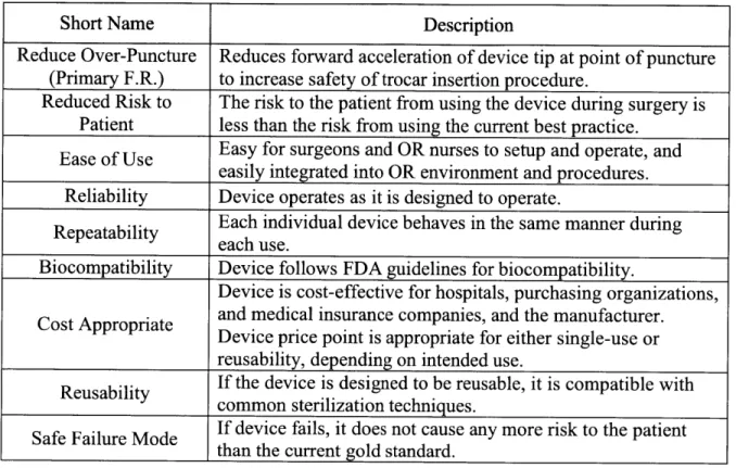
Table 1 shows the functional requirements that the proposed device should adhere to, as well as a brief explanation of each.
Table 1: Functional Requirements for the device in this project.
Short Name Description
Reduce Over-Puncture Reduces forward acceleration of device tip at point of puncture (Primary F.R.) to increase safety of trocar insertion procedure.
Reduced Risk to The risk to the patient from using the device during surgery is Patient less than the risk from using the current best practice.
Ease of Use Easy for surgeons and OR nurses to setup and operate, and easily integrated into OR environment and procedures. Reliability Device operates as it is designed to operate.
Repeatability Each individual device behaves in the same manner during each use.
Biocompatibility Device follows FDA guidelines for biocompatibility.
Device is cost-effective for hospitals, purchasing organizations, Cost Appropriate and medical insurance companies, and the manufacturer.
Device price point is appropriate for either single-use or
reusability, depending on intended use.
Reusability If the device is designed to be reusable, it is compatible with
common sterilization techniques.
Safe Failure Mode If device fails, it does not cause any more risk to the patient than the current gold standard.
I. Strategies:
Several high-level strategies were considered to address the primary functional requirement of reducing over-puncture. The first was redesigning the geometry and material of the trocar tip to reduce insertion force. This would lead to a lower net force in the direction of the patient at point of puncture and would reduce the resulting forward acceleration. Although doing so would
work to alleviate the problem of over-puncture, one concern with this strategy would be that a tip design that is more effective at cutting and penetrating might be less safe for the patient or
patient's unique anatomy might cause an insertion force on the order of what current trocar designs require, a trocar with greater penetrating effectiveness might have disastrous effects on underlying abdominal organs and major vessels.
The second strategy considered was dynamic blade retraction to cover the trocar tip as soon as it punctured the peritoneum. As opposed to currently available dynamic bladed trocars that employ a moving blade cover that must accelerate and catch up to the blade, this strategy involves causing the trocar tip itself to accelerate backwards into a protected recess. This backwards acceleration would counter the forwards acceleration caused by force imbalance at point of puncture and lead to reduced over-puncture as well as tip protection when the device is not in use. Challenges to this strategy include ensuring repeatability and reliability of the retraction mechanism as well as minimizing part count to remain price appropriate.
The third and final strategy involved using thermal or mechanical energy to decrease insertion force by inducing burning, cavitation, coagulation, or other forms of tissue destruction at the device tip. This strategy would attempt to apply a currently understood "energy method" of cutting in medical devices to a laparoscopic trocar. Although this strategy would greatly reduce the insertion force, the potential for extensive tissue damage and painful recovery would be
significant. In addition, the cost of such devices and associated capital equipment would likely be prohibitive.
After reconsidering the functional requirements, prior art, and the advantages and disadvantages of each strategy, the strategy of dynamic blade retraction was chosen. Secondary focus was given to device tip redesign to minimize insertion force since the blade would be protected when not in use.
IH. Concepts:
After deciding on the strategy to pursue, specific concepts were developed and considered. In order to fulfill the goals of the chosen strategy, the tip of the device should travel through a desired set of configurations. Although not critical to device function, when not in use or in its
packaging, the device tip would preferably be in the guarded configuration in order to protect its cutting integrity as well as prevent accidental injury. When penetrating through the peritoneum and surrounding tissue layers, the device tip should be fully exposed to maximize cutting ability and reduce insertion force. However, at point of puncture when the most distal point on the device tips pierces the most inferior layer of tissue, the device tip should return as quickly as possible to its guarded configuration.
From this desired motion, it is evident that the critical function of any concept to be considered is its ability to switch from exposed tip to guarded tip at point of puncture. In order to accomplish this, the device must be able to recognize point of puncture by detecting a signal associated with device tip puncture. Possible signals to detect include loss of force applied to the device tip in the axial direction away from the patient, visual view of the device tip exposed through the most inferior tissue layer, changes in tissue tension, and forward acceleration of the device. Loss of force at the device tip is the most direct indicator of tissue puncture and the most reliable indicator of when forward acceleration of the device tip will occur. In addition, it can be detected by purely mechanical and likely more cost-appropriate means. As a result, loss of opposing force at the device tip was chosen as the triggering signal for tip retraction.
Several mechanisms were considered to retract the device tip in response to a loss of force applied to the tip. The challenge in designing such a mechanism results from the direction in which the various forces are applied. In order for the device tip to retract and counter forward acceleration due to over-puncture, it has to move backwards into its guard element. The resistive force applied to the device tip by tissue tension during puncture acts in the direction of the
motion the tip travels during retraction. However, when this resistive force acts on the blade tip, the tip should remain static in order to continue penetrating tissue. It is only right after this resistive force disappears that the tip should move in the direction of retraction, which requires a net force on the tip that points in that direction. Before point of puncture, the mechanism must apply a net force on the tip which points towards the patient and is equal in magnitude to the resistive force applied by the tissue, despite the fact that this resistive force changes in magnitude as different tissue layers are punctured, in order to keep the tip static with respect to the device.
At and following point of puncture, the mechanism must apply a net force on the tip that points away from the patient in order to accelerate the tip away from the patient into its guard.
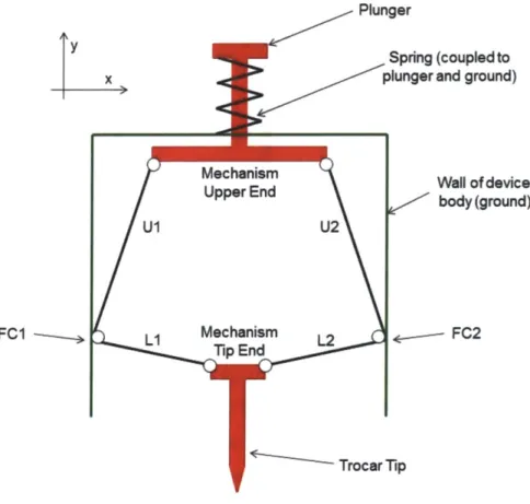
The chosen concept utilizes static friction and a high normal force created by a knuckle linkage to balance the force applied to the trocar tip during penetration and a mechanical spring to
deliver the retracting force at point of puncture. This is achieved through a biased two-force input "double-knuckle linkage" that converts axial force applied to the trocar tip into "normal force" that acts perpendicular to the axial direction. The mechanism is composed of four links that are joined to other components and to each other by pin joints. Figure 7 shows a simple schematic of this mechanism along with labeled points FC 1 and FC2 for reference.
y x
FC1
-Plunger
Spring (coupled to plunger and ground)
Aechanism Wall of device
Jpper End body (ground)
U2
echanism 12 * FC2
Figure 7: Simple mechanism schematic.
When a force, Ft, is applied to the trocar tip end of the mechanism in the positive y (axial) direction, this force is transferred through the two-force members L1 and L2 to the friction
contact points FCI and FC2. Since LI and L2 are positioned relatively close to parallel to the x (normal to axial) direction, they will apply a force, FL, at FC 1 and FC2 in primarily the x direction. The x component of force, FLx, will generate static friction between the friction contact points and the wall. The much smaller component of force acting in the y direction, FLy, will act to push the contact points upwards in the positive y direction. Figure 8a shows the trocar end of the mechanism and two-force members LI and L2 under this load with corresponding force components.
Y
x
Mechanism
tFi
Figure 8a: Tip end of mechanism under loadfrom trocar tip. Note that two-force members Li and L2
apply force at the device wall in primarily the x (normal) direction.
When force, Fs, is applied to the upper end of the mechanism in the positive y (axial) direction
by a tensioned spring, this force is transferred through the two force members U1 and U2 to the
friction contact points FCl and FC2. Since Ul and U2 are positioned relatively close to parallel to the y (axial) direction, they will apply force, Fu, at FC 1 and FC2 in primarily the y direction. The y component of force, Fux, will act to pull the contact points upwards in the positive y direction. The much smaller component of force acting in the x direction, Fuy, will act to pull the contact points away from the wall, reducing static friction. Figure 8b shows the upper end of the mechanism and two-force members Ul and U2 under this load with corresponding force
components.
----Y
t
Fs Mechanism Upper End U1 U2 Fuy Fu Fuy Fu Fu FuFigure 8b: Upper end of mechanism under loadfrom spring. Note that two-force members U] and U2
apply force at the device wall in primarily they (axial) direction.
Prior to use, the user presses a plunger coupled to the upper end of the mechanism, displacing the mechanism in the negative y direction, exposing the trocar tip from within its guard and
tensioning the spring at the top of the mechanism. With the plunger still depressed, the user presses the tip of the trocar to tissue, causing force to be applied to the tip end of the mechanism in the positive y direction and generating static friction at the friction contact points. The user then releases the plunger. From plunger release until point of puncture, the mechanism
experiences forces in the positive y direction at both the tip end and upper end. Due to the bias of the mechanism links, the force applied to the trocar tip generates a significant amount of static friction that is great enough to prevent these two forces from retracting the trocar tip.
When the force on the trocar tip goes to zero at point of puncture, the static friction force is also eliminated and a tensioned spring, which prior to point of puncture was too weak to overcome the static friction force, is now able to retract the trocar tip into its guard. A hard stop in the mechanism prevents the linkage from collapsing inwards rather than retracting the trocar tip. Figure 9 shows the sequence of mechanism configurations during penetration of the abdominal
wall. Forces applied to the plunger and wall (force on the wall is transferred through the device casing) applied by the user are shown in blue.
Figure 9: Mechanism tissue penetration sequence. From left to right: plunger depressed and blade
exposed, device tip pressed against tissue engages friction lock, plunger released and device driven through tissue, device tip penetrates tissue andfriction lock disengages, device tip retracts.
A proof of concept model for this mechanism was built and is shown in figure 10.
Figure 10: Proof of concept model of mechanism.
This model proved that the mechanism would behave as intended on a conceptual level and indicated the need for extensive force and geometrical analysis.
Mechanism Analysis:
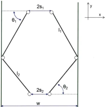
In order to further optimize the design of the mechanism, an analytical model was developed. Figure 11 shows the various geometrical parameters of the mechanism.
2s1 y x
&w
61 1 12 WFigure 11: Mechanism geometric parameters.
In order to calculate the various components of the force exerted by the two-force members, the angles 01 and 02 must be known. These are calculated using the dimensions of the mechanism as
c _ w - s1
02 =cs1 ws2 (2)
Where w is the horizontal distance between the two walls of the device body, si is half of the horizontal distance between the linkage pin joints at the upper end of the mechanism, S2 is half of the horizontal distance between the linkage pin joints at the tip end of the mechanism, i1 is the length of the two upper two-force members, and '2 is the length of the two lower two-force members.
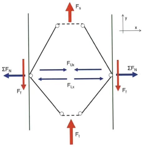
As previously described, during use and prior to point of puncture, the mechanism experiences two forces in the positive y direction; Fs is applied to the upper end of the mechanism by the spring, and Ft is applied to the tip-end of the mechanism by the trocar tip. Fux is the normal (x) component of the force applied to the wall by the upper two-force members due to the spring force. FLx is the normal (x) component of the force applied to the wall by the lower two-force members due to the force applied to the trocar tip.
A net normal force, EFN, is applied to each wall by the mechanism, pointing away from the
center of the mechanism. The magnitude of EFN is given as
F F
ZFN = F - Fu,= (3)
2tanO2 2tan,
This normal force generates a static friction force acting in the negative y direction at each wall, the magnitude of which is given by
Ff = F F ()
2 tan02 tan 1)
Where ps, is the coefficient of static friction between the mechanism and the wall. Figure 12 shows a schematic of the mechanism in this configuration with relevant forces labeled.
tFs Fux Fx
Ft
y x ZFNFigure 12: Mechanism under load from trocar tip and resultant forces.
The total static friction force acting in the negative y direction is given as
tan 02 tan 0,
In the configuration shown in figure 12, the mechanism is in static equilibrium when the net force acting in the y direction is zero, given as
(5)
(6)
This condition can also be expressed as
P, 't Fs > F + F (7)
tan62 tan 01
As long as this condition is met, the mechanism behaves as intended prior to point of puncture. At point of puncture, Ft goes to zero, causing the net normal force acting on the wall, EFN, to point inwards. As a result, the static friction force becomes zero and the net force on the mechanism in the y direction is simply F,, and the mechanism accelerates in the positive y direction and pulls the trocar tip in the same direction into its guard.
Alpha Prototype Design:
Following mechanism analysis, an alpha prototype was designed using SolidWorks CAD software. Figure 13a shows a model of the device with one half of the outer casing removed.
Figure 13b shows an exploded view bill of materials drawing of the alpha prototype iteration shown in figure 13a with one half of the casing removed.
---
1---1 6
Figure 13b: Exploded view bill of materials drawing of alpha prototypefirst design iteration with half of
outer casing removed
This design has 20 parts and employs a standard, off the shelf symmetrical scalpel blade as the trocar tip in order to minimize insertion force and reduce over-puncture. The blade is coupled to the mechanism with a transmission shaft that travels in bearing surfaces molded into the device casing. The casing is a two-part clamshell design comprised of two identical parts. In this prototype, the casing is glued or taped together, whereas in the final design the two sections would likely be joined with ultrasonic welding methods. For the alpha prototype, the casing was fabricated using rapid prototyping methods. It would be injection molded out of medical-grade plastic when made in production volumes.
The casing is designed to match current industry standards for trocars. The penetrating end of the trocar has an outer diameter of 0.5 inches, which is a commonly-used trocar dimension in the
U.S. The casing ends in a blunt-tipped blade guard into which the blade retracts at point of
puncture. Some consideration has been made to ergonomics in terms of handle size and plunger position; however, comfort for the user will be an area of focus in future iterations. Figure 14 shows the complete casing from two views with the blade and plunger also shown.
Figure 14: Device casing (blue) with plunger (red) and with blade (grey) exposed
The mechanism is made of plastic links that can be injection molded or machined. Again, these links were made with rapid prototyping processes for this prototype. The links are joined together with off the shelf steel dowel pins. The links and pins are significantly over-sized for the order of magnitude of force transferred through the mechanism. In order to choose the values of 01 and 02, a range of values was iterated through (5) using appropriate values for p, and Ft and over a range of values for F, that represented readily available springs. Values for 01 and
02 were chosen to ensure that condition (6) would be met with consistency. Finally, a standard compression spring provides retraction force to the mechanism. This spring was sized by finding the desired mechanism travel according to the geometry of the chosen blade. Appropriate values for ps and Ft and the chosen values of 01 and 02 were inserted into (5) to determine Ff, and a maximum spring force was chosen to ensure that condition (6) would be met. With these values
of force and displacement, a spring was chosen with an appropriate spring constant and force at maximum displacement. Figure 15 shows the upper section of the trocar with half of the casing removed, including the mechanism, plunger, and spring.
Figure 15: Upper end of alpha prototype first iteration showing mechanism (white, yellow, green), spring
(turquoise), plunger (red), connecting rods (orange), and device casing (blue).
Design Refinement: Flexure
Following the initial prototype design, it was noted that the mechanism experiences very small angular deflections at its joints. If the mechanism is replaced by a flexure in which the pin joints are replaced with flexural elements, the part count of the device is reduced from 20 to 8, or by
60%, and it is much simpler to assemble. As a result, a flexural mechanism was designed and
incorporated into the design.
The flexure is monolithic and uses comer-filleted flexural hinge elements to replace the pin joints in the original mechanism design. Figure 16 shows an outline of the flexure.
Figure 16: Top view ofmonolithicflexure mechanism.
The flexure fits into the design of the alpha prototype in place of the pinned mechanism and deforms in the same fashion. Figure 17 shows both the original mechanism as well as the flexure in place within the device casing.
Figure 17: Alpha prototype first (left) and second (right) iterations, showing, respectively, linkage
Although this design change carries the advantages described above, one potential liability is that the flexure has an internal stiffness that opposes angular deflections at the hinge points. As a result, for a given input force at the trocar tip, the static friction force at the wall would be lower since some of the tip force would be absorbed by the stiffness of the flexure. In order to be able to generate a high enough friction force to prevent retraction, 02 would have to be further reduced in order to increase the normal component of force generating friction. The closer this angle is to zero degrees, the easier it is for the tip end of the mechanism to reach a singularity and invert when force is applied to the trocar tip.
In order to solve this potential problem, the principle of reciprocity is employed in which an undesirable force or effect is reversed or repositioned to achieve a desirable purpose. In this case, the flexure is slightly oversized such that it must be very slightly compressed in the horizontal (x) direction in order to fit between the walls of the device. This creates an initial residual force pointing normal to the wall that generates static friction even when no force is
applied to the mechanism in the axial (y) direction. As a result, less force needs to be applied to the trocar tip in order to generate enough static friction to prevent tip retraction since there is additional residual friction caused by the flexure's internal stiffness. As such, equation 5 acquires a new term and is expressed as
FF
Fn +2FNr (8)
tant2 tan01
Where FNr is the residual normal force applied to the wall due to the stiffness of the flexure. In addition, as long as this residual friction force is less than the spring force, the spring is still able to retract the blade at point of puncture.
In order to determine the magnitude of FNr and validate manufacturing methods, the stiffness of the flexure is evaluated. Figure 18 shows the geometry and relevant dimensional parameters for a corner-filleted flexure hinge.
Figure 18: Corner-filletedflexure hinge and relevant geometric parameters, including leg length 1, fillet
radius r, in-plane thickness t, and out-ofplane thickness b.
The in-plane bending stiffness for one comer-filleted flexure hinge is given as [24]
KO (Ebt I + (9)
6r(2r +t2(4r+ t) 1 arctan + 4
12 l+2r t(4r+t)(6r2 +4rt+ t2)+ (2r+tX4r+ t)3
In order to find the sensitivity of (9) to each geometric parameter, the absolute value of the partial derivative of K0 with respect to each parameter is evaluated. The results are plotted
together over a range that reflects the nominal parameter values as well as a positive and negative estimated manufacturing tolerance. At any difference from the nominal parameter values, the stiffness of the flexure hinge result is most sensitive to the parameter whose partial derivative is greatest. Figure 19 shows the partial derivatives of the stiffness Ko with respect to each of the geometric parameters defined in figure 18 and appearing in (9) over a range that reflects the nominal dimensions of one of the flexure hinges included in the monolithic flexure
mechanism shown in figure 16 and an estimated manufacturing tolerance of +0.005". Associated MATLAB and Maple code is shown in Appendix A.
7000-(I) (w 6000 -5000 4000 0 2000-a. 100 0W 5 -4 -3 -2 -1 0 1 2 3 4 5
Difference from Nominal Parameter Value (inches) X 103
Figure 19: Partial derivative offlexure hinge stiffness Ko with respect to leg length I (green diamonds),
fillet radius r (pink squares), in-plane thickness t (blue circles), and out-of-plane thickness b (red asterisks) over estimated manufacturing tolerance range.
Over the range displayed in figure 19 including the chosen nominal dimensions, the angular stiffness of a corner-filleted flexure hinge is most sensitive to the in-plane thickness t. This fact will be critical in choosing and validating a manufacturing method for the flexure.
In order to find the linear axial (y direction) stiffness of the entire flexure, the static form of Lagrange's equation is employed. The full form of Lagrange's equation, using deflection in the
y direction as a generalized coordinate, is given as
d oT
oT JV
- - -- +--=F


![Figure 5: Various bladed puncture access devices including (clockwise from top left) a laparoscopic trocar [7], a bone marrow biopsy needle [8], assorted hypodermic needles [9], and laparoscopic verress](https://thumb-eu.123doks.com/thumbv2/123doknet/14169642.474405/21.918.154.749.539.855/various-puncture-including-clockwise-laparoscopic-assorted-hypodermic-laparoscopic.webp)
![Figure 6: Four high speed video frames showing trocar being driven through tissue simulator [12].](https://thumb-eu.123doks.com/thumbv2/123doknet/14169642.474405/23.918.199.717.116.451/figure-speed-frames-showing-trocar-driven-tissue-simulator.webp)