Publisher’s version / Version de l'éditeur:
Journal of Computing in Civil Engineering, 19, April 2, pp. 172-181, 2005-04-01
READ THESE TERMS AND CONDITIONS CAREFULLY BEFORE USING THIS WEBSITE.
https://nrc-publications.canada.ca/eng/copyright
Vous avez des questions? Nous pouvons vous aider. Pour communiquer directement avec un auteur, consultez la
première page de la revue dans laquelle son article a été publié afin de trouver ses coordonnées. Si vous n’arrivez pas à les repérer, communiquez avec nous à [email protected].
Questions? Contact the NRC Publications Archive team at
[email protected]. If you wish to email the authors directly, please see the first page of the publication for their contact information.
NRC Publications Archive
Archives des publications du CNRC
This publication could be one of several versions: author’s original, accepted manuscript or the publisher’s version. / La version de cette publication peut être l’une des suivantes : la version prépublication de l’auteur, la version acceptée du manuscrit ou la version de l’éditeur.
For the publisher’s version, please access the DOI link below./ Pour consulter la version de l’éditeur, utilisez le lien DOI ci-dessous.
https://doi.org/10.1061/(ASCE)0887-3801(2005)19:2(172)
Access and use of this website and the material on it are subject to the Terms and Conditions set forth at
Building integrated architecture/engineering/construction systems using smart objects: methodology and implementation
Halfawy, M. R.; Froese, T.
https://publications-cnrc.canada.ca/fra/droits
L’accès à ce site Web et l’utilisation de son contenu sont assujettis aux conditions présentées dans le site LISEZ CES CONDITIONS ATTENTIVEMENT AVANT D’UTILISER CE SITE WEB.
NRC Publications Record / Notice d'Archives des publications de CNRC:
https://nrc-publications.canada.ca/eng/view/object/?id=37a20da4-a4ce-4299-9814-ecb4cff33853 https://publications-cnrc.canada.ca/fra/voir/objet/?id=37a20da4-a4ce-4299-9814-ecb4cff33853
Building integrated
architecture/engineering/construction systems using smart objects: methodology and implementation
Halfawy, M.; Froese, T.
NRCC-48132
A version of this document is published in / Une version de ce document se trouve dans : Journal of Computing in Civil Engineering, v. 19, no. 2, April 2005, pp. 172-181
DOI:10.1061/(ASCE)0887-3801(2005)19:2(172)
Building Integrated Architecture/Engineering/Construction
Systems Using Smart Objects: A Methodology and Implementation
1Mahmoud Halfawy2 and Thomas Froese3
Abstract: Integrated project systems hold the potential for improving the quality while
reducing the time and cost of Architecture/Engineering/Construction (AEC) projects. A fundamental requirement of such systems is to support the modeling and management of the design and construction information and to allow the exchange of such information among different project disciplines in an effective and efficient manner. This paper presents a methodology to implement integrated project systems through the use of a model-based approach that involves developing integrated “smart AEC objects.” Smart AEC objects are an evolutionary step that builds upon past research and experience in AEC product modeling, geometric modeling, intelligent CAD systems, and knowledge-based design methods. Smart objects are 3D parametric entities that combine the capability to represent various aspects of project information required to support multi-disciplinary views of the objects, and the capability to encapsulate “intelligence” by representing behavioral aspects, design constraints, and life cycle data management features into the objects. An example implementation of smart objects to support integrated design of falsework systems is presented. The paper also discusses the
1
A Preliminary draft of this paper has appeared in the proceedings of the CIB-W78 conference on Distributing Knowledge in Building, Aarhus, Denmark, June 12-14, 2002.
2
Centre for Sustainable Infrastructure Research, Institute for Research in Construction, National Research Council, 6 Research Dr., Regina SK, Canada S4S 7J7; formerly, Dept. of Civil Engineering, Univ. of British Columbia, 2324 Main Mall, Vancouver, BC, Canada V6T 1Z4.
3 Dept. of Civil Engineering, Univ. of British Columbia, 2324 Main Mall, Vancouver, BC, Canada V6T 1Z4.
requirements for extending existing standard data models, specifically the Industry Foundation Classes (IFC), to support the modeling of smart AEC objects.
Keywords: integrated project systems, product models, interoperability, intelligent CAD
systems, industry foundation classes, falsework systems, smart objects.
INTRODUCTION
Integrated project systems are a key tool to help the industry to meet the increasing demands to reduce projects cost and time, and to improve the quality of the facility design and construction process. A fundamental requirement of such systems is to support the modeling and management of the project information and to allow the exchange of this information among project participants efficiently and effectively. The main functionality to be rendered by an integrated project system involves building and maintaining an integrated project database. This integrated database would serve to ensure the consistency and integrity of project data, enable efficient data sharing and exchange throughout the project life cycle, support tools interoperability, and enable timely access to up-to-date project information. Integrated project systems would also help to streamline project activities by allowing downstream disciplines to access the design information to evaluate the design and to assess the impact of design decisions on downstream project activities early in the design process.
AEC project information typically flows from the design phase to the construction phase to the facility management phase, with very costly and time-consuming feedback loops in the form of change orders and rework during the construction phase, or excessive maintenance work during the facility management phase. AEC objects typically involve large, complex, and dynamic information structures that are shared
among various project processes (e.g. design, specification, cost estimating, scheduling, etc.). A typical facility is comprised of a large number of such objects with distinct structural, functional, and behavioral characteristics, as well as complex dependencies and relationships. Different project disciplines usually have different views of the same object, and each view defines its own set of object attributes and methods.
Due to the highly interdependent and multi-disciplinary nature of AEC objects, the unidirectional style of information flow has often resulted in inefficient communication and exchange of project information, and subsequently caused project cost and time overruns, reduced quality and maintainability, loss of design intent, and the inability to efficiently access and exchange objects information in a timely manner. Historically, AEC systems were not so much concerned about sharing or exchanging data across different project domains. The objects embedded in these systems have typically implemented functionality and behavior that focus squarely on the specific requirements of the supported domain, with little or no regard to the common characteristics that these very same objects share across different domains. A clear manifestation of this phenomenon is the very limited object semantics exchanged by these systems as the project progresses from the design stage to the cost estimating or scheduling processes. Although the processes for estimating the cost or planning the construction of specific AEC objects significantly draw on the design semantics of these objects, we find that most AEC systems either define this semantics from scratch using an idiosyncratic approach, or replicate much of the semantics that was previously embedded in a software tool that was used in an upstream project activity. Lack of a standardized way to define and exchange objects’ semantics was a major factor that contributed to this limitation.
Attempts have been made to overcome some of these limitations through the use of Artificial Intelligence (AI) and knowledge-based techniques to add more intelligence and semantics to the objects. During the last two decades, numerous schemes for systematizing and representing design knowledge, cognitive computational models, design theories, and frameworks have been proposed (e.g. Gero 2000). Despite the significant body of knowledge currently available in this area, these models rarely produced commercial software solutions to the AEC industry. Most of the developed systems were primarily experimental research prototypes that could not attract the interest of the industry. An outcome from this research is the realization of the importance that design objects should embed the functional and behavioral semantics needed to support other downstream project activities. The view that design systems are purely analytical or drafting tools that are used at later and more detailed stages of the project have been replaced with a more integrative view of the role that these systems can play in the overall lifecycle of the project.
Parallel to these efforts, another thread of research was evolving with primary focus on the data modeling of AEC objects. Although this area started as a part of the AI approach, it became a separate research thread within the AEC IT research community. This research focused on the developing and implementation of standard data models to enable systems to share objects definition and semantics, and thus enable their integration and interoperability. Several data models for AEC objects were proposed. Examples include GARM, PISA, ATLAS, COMBINE, RATAS, OPIS, ICON, COMBI, and VEGA, just to name a few. (Eastman 1999) provided an excellent review of many of these models, which have, undoubtedly, contributed significantly to our ability to
represent AEC objects data. Many AEC models can now represent objects, their properties, and their inter-relationships in a comprehensive and accurate manner. Many efforts have been underway to standardize the representation of objects data to enable the exchange of project information in a standard and neutral format.
In this paper, we present an evolutionary model-based approach that builds on past research and experience in AEC product modeling, geometric modeling, intelligent CAD systems, and knowledge-based design techniques. This approach involves the modeling and implementation of “smart” AEC objects. Smart objects are three-dimensional (3D) design entities that combine the capability to represent various aspects of project information required to support multi-disciplinary views of the objects, and the capability to encapsulate intelligence and “knowledge” by representing objects’ behavioral aspects, design constraints, and life cycle data management features. This approach aims to enable efficient execution of design activities, sharing and exchange of project information, interoperability of discipline-specific software tools, streamlining the project processes, and facilitating the communication of project information among project participants. We view this approach as a major enabler to support the development of next-generation modular, interoperable, integrated, and intelligent AEC systems. The approach was used to implement an integrated software environment to support the design and management of falsework systems for highway bridge construction projects.
STANDARD DATA MODELS AS ENABLING TECHNOLOGIES FOR INTEGRATED PROJECT SYSTEMS
Developing standard data models has been a major thrust for academic and industrial research during the past decade. Several efforts have been underway to develop standard data models to support interoperability among various software tools and the development of integrated project systems. Many of the object models have reached a high level of maturity in supporting a wide range of project aspects. Most notably, the Industry Foundation Classes (IFC), developed by the Industry Alliance for Interoperability (IAI) (IAI 2003), now represents the largest scale standard AEC data model. The IFC model defines an integrated schema that represents the structure and organization of project data in the form of a class hierarchy of AEC objects. The schema defines the main data objects, their characteristics, and their inter-relationships. The IFC class hierarchy covers core project information such as building elements, the geometry and material properties of building products, project costs, schedules, and organizations. Instances of the IFC are initialized, linked, and assembled by application software to create an object model of the building project. Generally, the information from many types of software applications can be mapped into IFC data files. In this way, IFCs provide a standard data model and a neutral file format that enables applications to efficiently share and exchange project information.
The IFC model is the culmination of over a decade of research and development. The model has undergone four major releases, and many commercial software tools have already implemented IFC file exchange capabilities. The use of the IFC project data model could significantly improve the availability and consistency of project information, and would serve to integrate the multi-disciplinary aspects of the projects and facilitate the exchange of project information between function-specific software tools. As a result,
this would minimize the need for human intervention to re-interpret and re-format the data to marshal it between various tools, thus improving efficiency and eliminating the possibility of errors during data transformation.
In the simplest form of interoperability, the project model is communicated from one application to another in a data file (e.g. using ISO 10303 Part 21 format). Upon receipt of the data file, the receiving software will re-create the project model for further processing. As an example of the current capabilities of IFC-based file exchange, the following scenario has been implemented using tools developed by the Building Lifecycle Interoperable Software group (BLIS 2003).
• One tool is used to define the basic rooms and spaces of a building, including the names, areas, and other basic requirements. The resulting preliminary space plan is exported to an IFC data file.
• The IFC file is read into a two-dimensional technical drawing tool. In this tool, previously identified rooms are arranged into an overall floor plan, and various design details such as windows, doors, plumbing and mechanical systems, are added. The resulting design is then exported as an IFC file.
• The IFC file is opened by an energy analysis tool. Although the information had previously been constructed in a 2D drawing package, all of the elements have height and elevation properties, and can form full 3-D models in the CAD system. This tool performs energy simulations, and allows design revisions to the HVAC components, with the results again exported to an IFC file.
• The IFC file is opened in a tool that generates a 3-D virtual reality view of the project, allowing the user to rotate, zoom in and out, and walk-through the building. This tool then runs a series of design checks; rules which look for specific code conformance issues. Items that fail to pass the design checks, such as a room with insufficient fire egress provisions, will be highlighted in the 3-D model.
• The IFC file is opened in a tool that itemizes all of the physical components in the building, and maps their properties to an estimating database, to build up a complete cost estimate for the project.
This scenario describes the current state-of-the-art in IFC-based information integration. With the basic product modeling capabilities of the IFCs now reaching a high level of maturity and stability that has proved to be successful in many project scenarios, we are focusing on defining and developing ways to extend the model semantics and intelligence, data exchange mechanisms, project areas, and application domains. Specifically, we are working to extend the IFC model in several main directions:
• Adding support for smart AEC objects. We are working to extend the IFC model to
enable the encapsulation of objects intelligence and knowledge into the model. New IFC classes could be added to support smart AEC objects that represent richer semantics regarding objects behavior, management of evolutionary object data, and representation of the objects’ design rules, constraints, and procedures. This paper focuses on this research direction.
• Moving beyond file-based data exchange. Current implementations of IFC-based
of transferring data is very limited in its ability to manage a large pool of shared project information that is accessed concurrently by many users, or to enable transactional forms of data exchange between project parties and applications. The development of system architectures for distributed systems, such as IFC-based centralized object-oriented project repositories, is the next logical step.
• Moving beyond ad-hoc transactions. While the IFC model standardizes the
information content of an information exchange transaction, it offers no guidance to the context of these transactions. It is still left up to the two parties exchanging information to come up with ad-hoc agreements about what data are being exchanged, for what business purpose, with what constraints and obligations on each participant, etc. We are pursuing the formalization and possible standardization of data exchange protocols to support IFC-based transactions in distributed and heterogeneous environments.
• Extending the IFC model to address project areas that are currently not supported.
This could be achieved either by referencing and linking with other data modeling schemas (e.g. CIMSteel for structural design), by adding new property sets (e.g. to model specifications), or by introducing new IFC entities (e.g. facilities management classes).
• Extending the IFC application domains. The IFC model specifically addresses
building construction. Yet much of the content of the model is fairly generic and could be applied to other segments of the industry (e.g. bridges).
The next section discusses the fundamental characteristics and role of smart AEC objects. Then, the implementation of smart AEC objects to support integrated design of
falsework systems is presented. Finally, the requirements to extend the IFC model to support the modeling of smart object are outlined.
CHARACTERIZATION OF SMART AEC OBJECTS
AEC objects typically involve complex information structures and complex relationships. Objects’ data typically span several domains and involve the structural, functional, and performance characteristics of the object. A typical facility is comprised of a large number of inter-related objects. Moreover, different project disciplines usually have different views of the same object. Each view can be described as a set of attributes and methods. A major requirement of an integrated project system is to develop an integrated data model that can support the representation of project information across various project disciplines and to enable efficient exchange and sharing of project information. The model-based approach is an object-oriented data modeling methodology that aims to represent and structure the project data around a set of parametric AEC objects and to organize these objects in a class hierarchy according to their relationships.
Developing an integrated data model requires considering the interaction of different project disciplines at the object level. A typical AEC object model would encapsulate geometric and non-geometric data as well as methods to interface with other objects. It would also incorporate the knowledge required to synthesize and configure design alternatives. This integrated data model would enable fast generation of alternative design solutions. It would also enable capturing the information pertinent to different project views in one consistent and accurate representation that models the inter-dependencies of various model parameters. Object models explicitly define and capture the design rationale and any design assumptions. Constraints-based reasoning methods could also be
implemented to ensure that structural, functional, and performance constraints are satisfied and to ensure correct and realistic interaction among various domain objects.
Smart AEC objects are semantically-rich, product-centric data models that include an AEC object or object assemblies that represent not only the data attributes of these objects, but also encapsulate objects’ behavior and intelligence in the form of behavioral attributes, object inter-relationships, design rules, and configuration constraints. These objects are software components that implement the structural, functional, and behavioral characteristics of domain objects and support the representation of various aspects of project information pertinent to these objects. Smart objects are represented by a set of parametric attributes, methods, and a set of rules and/or procedures. Smart objects are particularly suitable to support configuration design problems where objects could be fully described using a set of configuration parameters and the rules that specify configuration constraints on the object and on sets of dependent objects can be explicitly defined. Seven basic characteristics for smart AEC objects have been identified:
First, a distinguishing characteristic of smart objects is their behavioral intelligence. Objects implement methods to ensure the integrity of their components and validity of their structural, functional, and behavioral parameters. The objects implement design rules to maintain the consistency of the design within each object and with regard to the interdependencies among various objects. For example, an object may adjust the values of some of its parameters based on changes in other parameters, or an object may re-configure or re-locate some of its components in response to changes in other related objects. Objects also implement behavioral features to ensure intelligent and realistic interaction with other objects in the system. For example, re-configuring or re-locating
one object may automatically cause re-configuration or re-location of other objects. Also, smart objects could implement methods to enable objects to ensure the data consistency and correctness within the object and in relation to other objects. Objects’ methods can also implement functions to derive or calculate more information from the defined object parameters. For example, an object’s method may automatically perform a quantity takeoff from the object geometric representation.
Second, a smart object can manage its evolutionary state throughout the project life cycle. Moving from conceptual to preliminary to final design stages, smart objects can keep track of their evolution history. Two possible evolution changes can be tracked: changes in object definition (or schema) and changes in object configuration (i.e. parameter values). Changes in objects’ schemas are tracked by maintaining a “version identifier” for each schema and defining methods to map between different schemas. Changes in object configuration are tracked by maintaining a list of the object “parameter set” along with a change version identifier and change information. Each object has a current “parameter set,” from which previous sets (or object states) can be navigated.
Third, smart objects can be arbitrarily complex by aggregating or referencing other objects and defining the rules that describe the inter-relationships and interaction between these objects. The advantage of defining objects as compositional assemblies of more primitive objects is two-fold: higher level objects are more intuitive and easier to work with from a design viewpoint; configuration rules and design constraints can be enforced to control complex objects configuration at higher level objects and therefore, ensure the consistency and validity of the design at all design stages.
Fourth, unlike traditional CAD objects, smart objects’ parameters not only describe the geometry but also describe other non-geometric information such as material, specification, cost, construction methods, etc. Smart objects integrate project information by representing and considering the interaction of different project disciplines at the object level. That is, the object model will glue together different project views pertaining to the object and enable interoperability of function-specific software tools addressing these views. Using the same object model, different project disciplines can access data relevant to their domains. Also, integrating different project views would enable developing methods to automate mapping between these views (e.g. automatically performing quantity takeoff).
Fifth, three-dimensional geometric representation of smart objects can be constructed given the set of object geometric parameters. Addressing configuration design problems requires accurate geometric representation of objects and their spatial relationships (e.g. for objects layout, interference detection, etc.). The use of 3D models would provide a wide range of benefits to various project processes. Project team members can more easily review and evaluate the design details and the construction process from multiple perspectives to identify potential problems. This could significantly improve the communication and collaboration among project teams. 3D models would also enable effective understanding of project information through visual interaction with and manipulation of design entities. The construction team can evaluate the constructibility of the design, and every design discipline team can assess the impact of their design decisions on other teams.
Sixth, smart objects can support and potentially automate many project activities such as quantities takeoff, automatic generation of analysis models and FE mesh for structural analysis, and checking interferences with other objects. By exploiting the dependencies among various parameters, changes can be propagated in such a manner to ensure that the object data remains up-to-date and reflects the current status of the project.
Seventh, smart object models can serve as the building blocks for knowledge-intensive design environments (Tomiyama and Mantyla 1998). Smart objects models support attaching computable or non-computable forms of objects-related knowledge. Computable knowledge can be represented declaratively in the form of production rules (e.g. configuration constraints or design rules) or procedurally in the form of computational methods (e.g. for calculating structural responses or materials quantity). Non-computable knowledge, such as unstructured documents, can also be linked to specific object parameters. Making object-related knowledge accessible through the object model could be used to automate the computation of some objects parameters and to provide an efficient method to index and access project documents. This will also allow the use of the object model to capture and represent the design knowledge and expertise in the form of object-centered design knowledge bases (Yoshioka et al 1998). As design becomes increasingly knowledge-intensive, the need to support the capturing, representation, and use of design knowledge becomes even more critical.
IMPLEMENTATION OF AN INTEGRATED FALSEWORK DESIGN SYSTEM USING SMART OBJECTS
A prototype software environment was implemented using the smart objects concept to support the integrated design, layout, structural analysis, cost estimating, and erection planning of falsework systems used for constructing cast-in-place concrete box girder bridges. Falsework objects can be thought of as specialized assemblies of the IFC columns and beams elements that are designed and erected to satisfy structural, schedule, and site constraints, among others. The software was implemented using the ObjectARX C++ class library that extends the AutoCAD environment (AutoDesk 1999). The system was developed in collaboration with Hua Construction, Inc., a Taiwan-based falsework subcontractor.
Falsework systems are complex structures in terms of the number of geometric and functional parameters that a designer must consider in order to develop a structurally safe and economical system. Falsework systems are typically designed and erected by a specialty contractor who needs to share and exchange project information with both design and construction teams. The input to this process typically consists of the bridge design documents, site topography (including soil data), and the construction schedule. The falsework subcontractor team will then define the design parameters along with the specification, cost estimating, and erection planning to meet the bridge design and construction schedule constraints. This process typically requires several iterations and is subject to stringent code requirements to ensure the stability and safety of the system.
To demonstrate the importance of sharing an integrated data model in a typical falsework project, let us consider the following scenario. Suppose that design changes have modified the layout or configuration of some falsework components. The objects representing these components need to re-build the structural model and perform
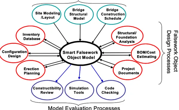
structural analysis on the new model, recalculate the quantities to be used for cost estimating, or perform checks to ensure that the new changes are within the code limits. By encapsulating the data relevant to each of these domains in the objects, it would be possible to automate and support inter-related project tasks across multiple domains while ensuring the consistency and integrity of the project data. Figure 1 demonstrates the role of smart objects in integrating falsework design and erection processes.
{Insert Figure 1 here}
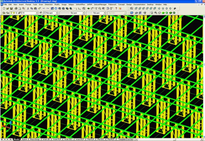
Falsework smart objects were developed to support efficient design as well as the sharing and exchange of project information between various project disciplines. The objects are implemented as ARX classes. These objects included the falsework segments, towers, beams, and grids (Figure 2). The object model encapsulated rules to ensure the consistency and correctness of the design throughout the project stages. A falsework system is comprised of a series of straight and/or curved segments. Each segment contains an array of towers positioned at regular or irregular grid points. In laying out a segment, the user specifies the segment parameters which include length, width, start and end offsets, number and spacing of towers in each direction, the dimensions of each tower, and the ground elevation and top elevation at the start and end of the segment. The user can define any number of segments. The user can also modify segments’ global properties (e.g. its elevation) as well as the location, height, and dimensions of individual towers. Dialogs for editing the grid dimensions and towers configuration are also implemented. The user can also place layers of beams longitudinally or transversely in a segment. The system has been developed to primarily support the following use cases: 1) Create, configure, and modify falsework segments; 2) Perform structural modeling and
analysis; 3) Produce layout drawings; 4) Produce bill of materials and cost estimates; 5) Planning and visual simulation of the erection schedule in relation to the bridge construction schedule; and 6) Edit the object library.
{Insert Figure 2 here}
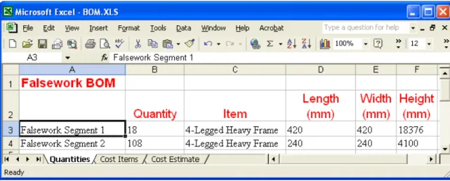
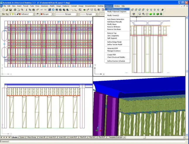
A number of different configurations for each object are stored in a library from which a falsework designer would select the components and configurations that are most suitable to the project at hand. Designers then specify values for the pre-defined objects parameters. Based on these values, the objects determine their 3D geometric configuration and can perform several functions such as generating a bill of materials for cost estimating (Figure 3) or a finite element model to check the stability against different loading conditions. Designers position the objects in their exact location by referencing points on the bridge structure or on the site. Figure 4 shows an example of a complete falsework system. Objects’ behavior was modeled and implemented in the form of methods to control their response to user modifications in order to ensure that the objects will remain in a consistent and valid state and that the relationships to other objects are maintained. Designers can modify different objects (e.g. tower heights) and the impact of any changes is automatically propagated by the object methods to other dependent objects (e.g. beams layers).
{Insert Figure 3 here}
Objects also implemented methods to store, access, and manage the multi-disciplinary project information. By encapsulating the data relevant to different project disciplines, it
would be possible to automate and support inter-related project tasks across multiple disciplines while ensuring the consistency of the project data. For example, if the objects’ configuration changes, the objects can modify the structural model and re-perform structural analysis, recalculate the quantities to be used for cost estimating, or perform checks to ensure that the new changes are within the code limits.
{Insert Figure 4 here}
Components of the falsework systems are represented, organized, and managed as parts of an integrated object model. Users could navigate through the object model using the “project explorer” interface (Figure 5). This interface provides a hierarchical view of various pieces of project information such as the falsework product model, schedule, cost estimate, and documents. Users could associate pieces of information between different views to indicate “relationships” between different project aspects. For example, users could drag schedule activities and drop them onto falsework components to indicate that a particular component is dependent on one or more activities. As a result, a 4D simulation of the erection process could be automatically generated.
{Insert Figure 5 here}
EXTENDING IFC SCHEMA TO SUPPORT MODELING OF SMART OBJECTS
Currently, the IFCs are used to exchange the form and structure of a project model between applications. Each application is responsible for implementing the appropriate object behaviour; there is no notion of exchanging or standardizing this behaviour. Yet, users might reasonably expect these objects’ behaviour to be similar between different
applications. Extending the IFCs so that they could incorporate object behaviour within the model could capture this notion of common object behaviour, and may improve the efficiency of software development since the behaviour would not need to be re-created independently within each application.
While the current IFC model does not address behavioral or functional aspects of the objects, traditional knowledge-based techniques do not address the modeling of the multi-disciplinary objects’ data in a complete and comprehensive manner. Representing a hybrid of the two approaches, smart objects are positioned to play an integrative role that would build on the strength of both approaches to allow software tools to share and exchange semantically rich AEC object models. By supporting the capabilities of smart objects in the IFC model, systems will no longer merely represent and exchange objects’ static data, but more knowledge and semantics about design, including behavior, objects’ relationships, design rules, and constraints will also be represented and exchanged. Extending the IFC model to support smart objects would enable the addition of more semantics (i.e. behavior and knowledge) to IFC objects and allow the definition of application-specific custom complex objects that are composed of more primitive objects.
The IFC model defines a flexible, yet powerful, mechanism that allows extensions to the model through the use of the IfcPropertySet entity. An IFC property set could be used to define a set of properties (IfcProperty entities or other nested IfcPropertySet entities), and can be linked to any number of IFC objects using the IfcRelAssignsProperties entity. Representing and linking objects’ behavior could be supported following a similar approach. A new IfcBehaviorDef entity could serve as a container for object-related behavioral if-then rules as well as procedures, both of which are supported by the
EXPRESS language. IfcBehaviorDef entities can be linked to any number of IFC objects using another entity called IfcRelAssignsBehavior.
Objects’ behavioral constraints can be modeled more naturally using if-then production rules. In a typical IfcBehaviorDef entity, rules may reference the attributes of the same object or other related objects. The rules could be used to enforce design constraints to maintain the consistency and correctness of the design. For example, in the falsework model described in this paper, a constraint was implemented to specify a relationship between a tower type and its minimum dimensions, and the change of a tower type would require changing certain dimensions. Also, changing the towers height would require changing the supported beams elevation. Rules could be formulated to enable automatic propagation of these changes. For example, a rule stating that “if tower type is X then dimension Y = Z” could be used to represent the dependency between a tower type and dimensions, while a constraint stating that the beams’ elevation equals the towers’ top elevation could be used to propagate the second change.
Rules could also be used to enforce spatial constraints among different objects (e.g. adjacency or connectedness constraints). Changing the location of an object may require that other related or connected objects be relocated according to certain rules. For example, moving the falsework towers would also require moving the supported beams in order to maintain the correctness of the system. Supporting the propagation of this type of change could be supported by adding an entity that represents “anchors” between different objects as well as a mechanism or “reactors” to detect that changes have occurred in some objects. Anchors can be thought of as another form of relationships between objects that indicates “spatial-dependencies” between objects.
The definition of objects’ behaviour would typically become part of the IFC model-development process. The domain and modelling experts that initially define the IFC objects would define the constraints and procedures, which would then be available for use by software developers and end users.
There are several possibilities for how these procedures and constraints in object behaviour definitions might be executed by applications. For example, each application could implement or interface with a rule-processing engine, possibly as part of a standard IFC toolkit. Alternatively, procedures could be defined in behaviour sets by their interface (i.e. signature) and implemented using standard component interfaces (e.g. a standard COM interface), or using web services. Applications could then interact with standardized component libraries or web services to execute these procedures. For example, a “CalculateFalseworkBillOfMaterials” procedure may be implemented in a standard interface (e.g. IFalseworkBillOfMaterials), or as a web service. Other procedures could be implemented to check some object values or to retrieve some data (e.g. form an online product repository).
Another possible extension is the capability to represent arbitrarily complex object assemblies where an object can be composed of more primitive objects. For example, a tower object is composed of a set of column and beam primitives. IFC models a set of pre-defined complex or container objects (e.g. building, building storey). A new IfcProduct-derived class (e.g. IfcComplexObject) could be used to support this extension. This class could define a list of references to its component entities. This would enable the modeling, managing, and accessing arbitrarily complex and hierarchical objects as one unit. To define the inter-relationships among the set of component objects, an
IfcBehaviorDef entity could be used to specify the rules of interaction between these objects. Similarly, the IfcBehaviorDef object could then be linked to the IfcComplexObject instance using an IfcRelAssignsBehavior object.
Objects are initially defined using a simple set of parameters and evolve into a more comprehensive and detailed representation as more design iterations are performed. The IFC model represents a static snapshot of objects data with no ability to record or track changes that the object has gone through during various design stages. The IFC model defines an entity, IfcOwnerHistory, which supports tracking the agent who performed the change. However, it does not define any mechanism to track the changes themselves. An important feature of smart objects is their ability to record different changes that occur to the object state during different design stages. To add the capability to track and manage evolving objects’ data, a mechanism for representing and managing the evolution and change of the objects’ data sets is required. One possible approach would involve the use of property sets to track the current version and the history of changes in each object. For each IFC object, a corresponding version property set that defines the object attributes will be added. In addition, the property set will define an attribute for the version number, an attribute to reference the previous version property set, if one exists, along with attributes that record change information (e.g. cause for change, time and date, etc.). Using this capability, the IFC model will evolve with the project while representing a complete recording for design changes throughout the project. Such a model could be later transferred and used to support the facility management activities.
This paper presented a model-based approach that employs “smart objects” to implement integrated project systems. Smart objects are an evolutionary step that builds on almost two decades of research and experience. The paper discussed the main characteristics of smart AEC objects and presented the requirements to extend the IFC data model to support the modeling of smart objects. Besides serving as data models that integrate multi-perspective project views and encapsulate behavioral object intelligence, smart objects also enable the exchange of semantically-rich data models between different software tools.
Smart objects could potentially offer many benefits to the design process: (1) Modeling behavioral aspects within individual objects as well as between inter-dependent objects, and integrating those aspects with the structural and configuration aspects of AEC objects; (2) Automating routine decisions and design checks that could be based on geometric or non-geometric objects parameters; (3) Automating propagation of changes and enforcing design constraints and rules to maintain the design consistency and validity; (4) Integrating design with other project activities (scheduling, estimating) and thus facilitating the information sharing across project activities; (5) Reducing the time needed to design complex objects and allow designers to focus on design issues and to perform quicker design iterations; (6) Provide feedback to designers if any constraints or requirements are violated; and (7) Capturing and encapsulating design rationale into these objects. The prototype falsework design system has demonstrated the utility and potential of the smart objects approach to support the development of integrated project systems. The same approach could be utilized to develop other similar systems within the scope of a specific project discipline or across several disciplines.
ACKNOWLEDGEMENTS
We gratefully acknowledge support for this work from the Natural Sciences and Engineering Research Council of Canada, Collaborative Research Opportunities Program, and from Hua Construction of Taiwan.
REFERENCES
AutoDesk Inc. (1999), “ObjectARX Developer’s Guide.”
“BLIS, Building Lifecycle Interoperable Software,” (2003),http://www.blis-project.org.
Eastman, C.M., “Building Product Models,” (1999), CRC Press, Boca Raton FL.
Halfawy M.R. and Froese, T. (2002), “A Model-Based Approach for Implementing Integrated Project Systems,” Proceedings of the Ninth International Conference on Computing in Civil and Building Engineering (ICCCBE), April 3-5 Taipei, Taiwan.
Halfawy M.R. and Froese, T. (2002). “Modeling and Implementation of Smart AEC Objects: An IFC Perspective,” Proceedings of the International Council for Research and Innovation in Building and Construction CIB w78 conference 2002, Aarhus School of Architecture, 12 – 14 June 2002, Volume I, pp. 45-52.
“International Alliance for Interoperability (IAI)” (2003). http://www.iai-international.org.
Gero, J. S. (ed.) (2000). “Artificial Intelligence in Design’00”, Kluwer, Dordrecht, 719pp.
Wix, J. and Liebich, T. (1997). “Industry Foundation Classes Architecture and Development Guidelines,” International Alliance for Interoperability (IAI).
Yoshioka, Y., Shamoto, Y., and Tomiyama, T. (1998). “An application of the knowledge intensive engineering framework to architectural design”, In Finger, S., Tomiyama, T., Mantyla, M., editors, Knowledge Intensive CAD-3, Workshop on Knowledge Intensive CAD-3.
Yoshioka, M., Sekiya, T., Tomiyama, T. (1998). “Design Knowledge Collection By Modeling,” Proceedings of the Tenth International IFIP WG 5.2/5.3 Conference PROLAMAT, Trento, Italy.
Smart Falsework Object Model Bridge Structural Model Structural/ Foundation Analysis BOM/Cost Estimating Erection Planning Site Modeling /Layout Bridge Construction Schedule Configuration Design Constructibility Review Project Documents Inventory Database Code Checking Simulation Tools Falsew ork Obj e ct D e sig n P ro c e s se s
Model Evaluation Processes Smart Falsework Object Model Bridge Structural Model Structural/ Foundation Analysis Structural/ Foundation Analysis BOM/Cost Estimating BOM/Cost Estimating Erection Planning Erection Planning Site Modeling /Layout Bridge Construction Schedule Configuration Design Configuration Design Constructibility Review Project Documents Project Documents Inventory Database Inventory Database Code Checking Simulation Tools Falsew ork Obj e ct D e sig n P ro c e s se s
Model Evaluation Processes
Figure 5: Project Explorer, Product Model, and Process Model of an Example Falsework System