HAL Id: hal-00143150
https://hal.archives-ouvertes.fr/hal-00143150
Submitted on 24 Apr 2007HAL is a multi-disciplinary open access archive for the deposit and dissemination of sci-entific research documents, whether they are pub-lished or not. The documents may come from teaching and research institutions in France or abroad, or from public or private research centers.
L’archive ouverte pluridisciplinaire HAL, est destinée au dépôt et à la diffusion de documents scientifiques de niveau recherche, publiés ou non, émanant des établissements d’enseignement et de recherche français ou étrangers, des laboratoires publics ou privés.
FETI-DP method
Ahmad Mobasher Amini, David Dureisseix, Patrice Cartraud, Natacha
Buannic
To cite this version:
Ahmad Mobasher Amini, David Dureisseix, Patrice Cartraud, Natacha Buannic. A micro-macro strat-egy for ship structural analysis with FETI-DP method. 3rd European Conference on Computational Mechanics, Jun 2006, Lisbon, Portugal. pp.1-10. �hal-00143150�
III European Conference on Computational Mechanics Solids, Structures and Coupled Problems in Engineering C.A. Mota Soares et.al. (eds.) Lisbon, Portugal, 5–8 June 2006
A MICRO-MACRO STRATEGY FOR SHIP STRUCTURAL ANALYSIS
WITH FETI-DP METHOD
A. Mobasher Amini1, D. Dureisseix2, P. Cartraud1and N. Buannic3 1G`eM, CNRS UMR 6183 / ´Ecole Centrale de Nantes
1, rue de la No¨e, BP 92101 - 44321 NANTES CEDEX 3 - France
e-mail: [email protected] , e-mail: [email protected] 2LMGC, CNRS UMR 5508 / Universit´e Montpellier 2
CC048,Place E. Bataillon, 34095 MONTPELLIER CEDEX 5, France e-mail: [email protected]
3Principia Marine
1, rue de la No¨e, BP 22112 - 44321 NANTES CEDEX 3 - France e-mail: [email protected]
Keywords: FETI-DP Method, micro-macro, Ship Structure.
Abstract. In the analysis of ship structures at small scale, with structural details heterogeneities
and because there is only one prototype produced, which is the final product, the designers rely on finite element simulations. The finite element discretization of such structure, leads to a huge global numerical model, that suffers for computational cost and memory resource that may be unaffordable. In such a case, a multi-scale analysis should be performed. The classical local-global analysis that is used by engineers has several limitations such as:
• structure details are not periodic, therefore classical homogenization methods are not
easily applicable;
• edge effects are not take into account;
• zooming techniques are not easy to use: the gluing they require with the global scale often
introduces artificial edge effects.
This paper presents a micro-macro strategy based on the domain decomposition FETI-DP method as the solver in analysis of ship structure. With this approach, the two scales (micro and macro) are coupled during the iterations of the solver and we can consider the structural details in areas of interest, area where the fine mesh is used and a sub-domain is located. Performances are discussed and results in term of convergence are presented for several exam-ples.
1 INTRODUCTION
Analysis of a large system like ship structure, to obtain the fine scale results is one of the industrial challenges today. Since there is often only one prototype produced, which is the final product and because real-scale test of such structures are very expensive and difficult, the de-signers now often rely on finite element simulation. Due to the classification society rules and regulations, extensive use of numerical simulations started only recently in this domain of en-gineering. With the advent of new design for ships, the old rules and regulations were obsolete and engineers shifted to the numerical simulation and in particular to the finite element method. Due to different specifications, several discretized models are used:
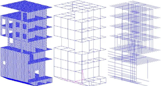
• for global behavior of the structure, and regulations requirements of numerical tests, a so
called coarse finite element model is used, see Figure 1;
• for local stresses, and to take into account all details (skylight, doors, . . . ) a model at a
finer scale is required;
• for vibration analysis, . . . ; • for fatigue life assessment , . . . ;
Figure 1: Global finite element model
To obtain a solution for the whole structure as well as a local solution near the details, a small scale discretized model is required. This would lead to a huge global finite element model with large number of unknowns that is very expensive to solve. Because of this large number of un-knowns, memory and processors limits, computing this kind of problem with a classical direct technique is not feasible at the moment, even with last generation sparse solvers. Therefore, us-ing a simplified global model is mandatory and engineers have used approximate method based on super-element or local-global analysis.
Briefly, the local-global methods, which are used in engineering consist of several steps:
• Solving a local or microscopic problem to derive its global behavior for very parts of the
structure;
• Construction of a global or macroscopic model of the ship with an equivalent
homoge-nized constitutive behavior by the results of the first step;
• Once the global model is solved, recovering the solution on the small scale of the details
with a post-processing step.
The use of such a strategy raises several difficulties:
First, we can not use the periodic homogenization approach, since the structural details are not periodic. So we need the appropriate assumptions on boundary conditions for the local prob-lems dealing with structural details.
A. Mobasher Amini, D. Dureisseix, P. Cartraud, N. Buannic
needed to recover the small scale solution. Depending on the selected boundary conditions, ar-tificial edge effects may appear that pollutes the local stress computations. These edge effects, as well as approximations in the homogenized behavior, are the consequence of loosely coupled global and local computations.
To overcome to the above mentioned drawbacks, we will use domain decomposition methods that will allow to restore the coupling between the different scales along iterations. Numerous domain decomposition methods are discussed in the literature. They differ in the way gluing conditions are expressed between neighboring substructures.
Another difficulty lies in the fact that complex structures as ships are assemblies of different structural elements like shells, joints and stiffeners. Usually the stiffeners are modeled with beam finite elements while various panels uses shell or plate finite element and joints use spe-cial transition elements.
Therefore, we propose to use a domain decomposition approach suited to:
• couple local fine scale models of predefined areas (or sub-domain);
• glue these local models to areas without zooming, i.e, with a coarse finite element model; • provide a mechanism to homogenize fine scale sub-domains to coarse finite elements; • deal with previously mentioned heterogeneities.
In this article, we will not tackle the problem of gluing local models to coarse models. We pro-pose to use the dual-primal version of the FETI method, which is briefly described in Section 2. The same Section recalls the technology used in such methods to deal with classical hetero-geneities.
The Section 3 presents the problem of interface in the case of the 3D mesh of the ship struc-ture and different heterogeneity in this strucstruc-ture. We will present the results of the two simple problems and a real 3D problem of a slice of the ship structure in Section 4. The results and conclusion will be in the Section 5.
2 GENERAL DESCRIPTION OF THE FETI-DP METHOD
Domain decomposition methods are both an efficient and flexible tool for structural analysis [6],[4]. As an iterative approach, they often outperform direct methods when the size of the model increases, and they allow a parallel treatment of the resolution phase. In this article, we are not concerned with the parallelization of the resolution, but we focuss on the modularity, especially for coupling different areas (different sub-domains) that may have been modeled dif-ferently, or with different discretization levels.
To reach numerically scalability, the domain decomposition method needs a multi-scale fea-ture, mainly to be able to built a coarse problem that maintains the convergence rate weakly dependent on the number of substructures, among these methods, one can refer to BDD [7], CBDD [8], aggregation technique [10], [9], FETI [3], FETI-DP [2], [1], LATIN micro-Macro [5]. Moreover, when this coarse problem is related to an homogenized model of the same struc-ture, this provides an efficient tool to deal with heterogeneous structures.
The different versions of the FETI method (FETI-1 [3], FETI-2, FETI-DP [2], [4], . . . ) belongs to the family of the non overlapping domain decomposition methods with lagrange multiplier.
These methods have been developed for solutions of the large scale systems of equations in structural analysis by finite element method. Among all the domain decomposition methods that were presented by many others author, we choose the FETI-DP method for the following reasons:
Usually with a multi-scale domain decomposition method, the reference problem is split into sub-domains and the coarse space problem is numerically built from this fine scale description. The coarse problem can be discrete by nature, and is not always related to any finite element model.
In the case we are interested in, the coarse problem is already provided, and the reference prob-lem is built from this coarse probprob-lem by selecting zooming area that are coarse finite eprob-lements (a panel or a stiffener, for instance). A selected coarse finite element is re-meshed at a fine scale with the corresponding structural details (skylight, door, . . . ) and is identified as a sub-domain. The initial coarse finite element possesses nodes that are suitable to be chosen as corner nodes of the FETI-DP method.
Moreover, as detailed in the following (see Figure 2), the coarse finite element model consti-tutes a structural homogenization of the detailed sub-structures, and the compatibility of coarse displacement field is ensured automatically with neighboring coarse elements.
Figure 2: Coarse finite element model and a fine scale sub-domain
2.1 Basic FETI-DP method
Let us consider the domain Ω, decomposed that into N non-overlapping sub-domains (or
substructures) Ωs. Let Ks, usand fsbe the stiffness matrix, displacement and prescribed force
vectors associated with sub-domain of Ωs, respectively. By splitting usinto corner and reminder
A. Mobasher Amini, D. Dureisseix, P. Cartraud, N. Buannic u = " ur uc # = u1 r . . . uNrs uc (1)
Where uc is the global or primal solution vector of the corners degrees of freedoms (d.o.f) and
us
r is solution vector of the remaining sub-domains degrees of freedoms. With this kinematic
description, the solution at corner point is globally continuous. Using this notation, we can split the sub-domain stiffness matrix into:
Ks= " Krrs Krcs KsT rc Kccs # (2) By writing the equilibrium equation for each sub-domain in the global form and considering the continuous boundary condition on the interface of the sub-domains we will have the following relations: Krrsusr+ KrcsBcsuc+ Bs T r λ = f s r f orallsin1, ..., Ns (3) s=Ns X s=1 BscTKrcsTusr+ s=Ns X s=1 BcsTKccsBcsuc = s=Ns X s=1 BcsTfcs= fc (4) Where Bs
c are boolean matrices that map the local corner d.o.fs of a sub-domain to the global
corner d.o.fs:
usc = Bcsuc (5)
The interface continuity condition can be written as follows:
s=Ns X
s=1
Brsusr = 0 (6)
where Brsare signed boolean matrices.
With the above equations and after some algebraic transformations, we obtain the following
dual-primal problem. with Lagrange multiplier λ and primal displacement uc as unknowns.
" FIrr FIrc FIT rc −K ∗ cc # " λ uc # = " dr −f∗ c # (7) where: FIrr = s=Ns X s=1 BrsKrrs−1BrsT (8) FIrc = s=Ns X s=1 BrsKrrs−1KrcsBcs (9) Kcc∗ = Kcc− s=Ns X s=1 (KrcsBrs)TKrrs−1(KrcsBcs) (10)
dr= s=Ns X s=1 BrsKrrs−1frsfc∗ = fc− s=Ns X s=1 BcsTKrcsTKrrs−1frs (11)
The symmetric positive definite dual interface problem is obtained by condensing the uc on the
λ: (FIrr + FIrcK ∗−1 cc F T Irc)λ = dr− FIrcK ∗−1 cc f ∗ c (12)
We use the preconditioning conjugate gradient algorithm (PGC), as a solver of the above inter-face problem. Indeed because the number of unknowns in the above equation can be large and because computing and assembling that for each substructure would be very expensive, (2.1) is not solved by a direct method.
The kernel of the equation (2.1) is the computation of the coarse FETI-DP matrix Kcc∗. The
matrix Kcc∗ is sparse and its pattern is that of a stiffness matrix obtained by considering only the
super-elements defined by the corner nodes.
2.2 Preconditioning for heterogenous problems
Like all iterative methods, FETI-DP solver performances depend on spectral properties of the matrix of the linear system and demand a good conditioning of the equations. In this article, we do not develop a new preconditioner for FETI-DP method. The preconditioner [4] are:
FD −1 Irr = s=Ns X s=1 WsBrs " 0 0 0 Ss brbr # BrsTWs (13)
where, for the Dirichlet preconditioner :
Sbs rbr = K s brbr − K sT ibrK s−1 ii K s ibr (14)
and for the Lumped preconditioner:
Sbsrbr = Kbsrbr (15)
Ws is a scaling diagonal matrix for the heterogeneous cases and i, b and r are internal nodes,
boundary nodes and total internal and boundary nodes, respectively. For more informations the reader can refer to [3], [2], [1].
3 INTERFACE PROBLEM IN THE CASE OF SHIP STRUCTURES
The ship structure is assemblage of the very different structural elements such as shell, plate , stiffeners, joints, etc. We consider stiffeners in two categories, primary and secondary stiffeners. All secondary stiffeners is considered into the plate sub-domain and all primary are consider like the one sub-domain. As a rule we decompose the structure in the line of intersection of the all plate and primary stiffeners. For this reason in interface line there are three lagrange multiplier.
We applied the DKQ element (with 6 d.o.fs u, v, w, θx, θy, θz at each node) and 2 node beam
A. Mobasher Amini, D. Dureisseix, P. Cartraud, N. Buannic
4 NUMERICAL EXAMPLES
For illustration of the performance of the above mentioned method we present two examples. The problem is a model problem of a 2D stiffened plate and is used to test the convergence of the method. The second problem concerns a 3D analysis of a slice of a ship with a fine finite element model.
4.1 2D stiffened plate
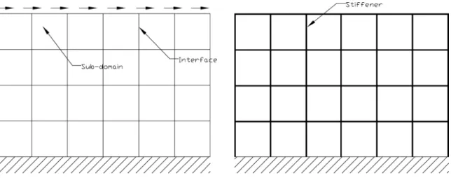
We consider herein the 2D static deflection and plane stress analysis of a plate with (problem I) or without (problem II) stiffeners. Both are related to a rectangular domain, clamped on the bottom side.
We use DKT elements (three node triangular plane stress elements with two d.o.fs at each node)
made with steel (young’s modulus E = 2.0 × 10¹¹N/m2and Poisson’s ratio ν = 0.3)
For problem II, an assembling of plates and stiffeners is considered. The stiffeners are dis-cretized with two node beam elements (three d.o.f for each node, two displacements, u and
v, and rotation θ). The material characteristics of the stiffeners are Young’s modulus E = 2.0 × 10¹¹ N/m2, Poisson’s ratio ν = 0.3, cross section area S = 0.00295 m2 and section
moment of inertia to I = 1.4471 × 10⁻⁶ m4 for bending.
We suppose that the stiffeners lie on the interfaces of the decomposition into sub-domain. We prescribe an uniform shear force on the top side of the two above problems (see Figure 3).
The results of the above mentioned problems with different sub-domain sizes H and delement
Figure 3: Plane stress problem
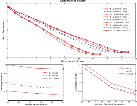
sizes h with application of the FETI-DP solver and Dirichlet preconditioner are shown in Fig-ures 4 and 5.
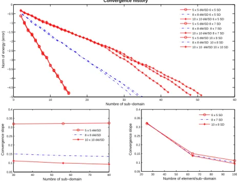
The rate of convergence is still higher for the problem without stiffeners, even when using the Dirichlet preconditioner. With diagonal scaling and three lagrange multipliers this behavior is still to be studied to recover the initial convergence rate.
2 4 6 8 10 12 14 16 18 20 −6 −5 −4 −3 −2 −1 0 Numbre of sub−domain
Norm of energy (error)
Convergence history 5 x 5 élé/SD 6 x 5 SD 8 x 8 élé/SD 6 x 5 SD 10 x 10 élé/SD 6 x 5 SD 5 x 5 élé/SD 8 x 7 SD 8 x 8 élé/SD 8 x 7 SD 10 x 10 élé/SD 8 x 7 SD 5 x 5 élé/SD 10 x 8 SD 8 x 8 élé/SD 10 x 8 SD 10 x 10 élé/SD 10 x 10 SD 30 40 50 60 70 80 0.35 0.4 0.45 0.5 Numbre of sub−domain Convergence slope 5 x 5 élé/SD 8 x 8 élé/SD 10 x 10 élé/SD 20 30 40 50 60 70 80 90 100 0.35 0.4 0.45 0.5 Numbre of element/sub−domain Convergence slope 6 x 5 SD 8 x 7 SD 10 x 8 SD
Figure 4: Convergence behavior (plate without stiffener)
4.2 A 3D analysis of a slice of ship
In order to tackle a more realistic problem, we consider a slice of the passenger ship as shown in Figure 2. Pre and post processing is performed with the FE code Cast3M (CEA sacly, France) and reduction is achieved in a prototype FE platform in Matlab environment.
The finite element characteristic of this structural model as shown in Table 4.2:
Item No.
Length, Breadth, Depth 11.6 m, 9.43 m, 22.1 m
Number of fine mesh nodes 11082
Number of element 11065
Number of d.o.fs 66492
Number of sub-domain (mesh coarse) 237
Table 1: Characteristic of the slice of the ship.
5 CONCLUSIONS
In this paper we was succeed to use domain decomposition method and FETI-DP method such as solver in the static analysis of the ship structure. We considered one coarse mesh that the fine mesh (structural details) is hidden behind that and also we consider all primaries stiffeners in one sub-domain.
A. Mobasher Amini, D. Dureisseix, P. Cartraud, N. Buannic 0 10 20 30 40 50 60 −5 −4.5 −4 −3.5 −3 −2.5 −2 −1.5 −1 −0.5 0 Numbre of sub−domain
Norm of energy (error)
Convergence history 5 x 5 élé/SD 6 x 5 SD 8 x 8 élé/SD 6 x 5 SD 10 x 10 élé/SD 6 x 5 SD 5 x 5 élé/SD 8 x 7 SD 8 x 8 élé/SD 8 x 7 SD 10 x 10 élé/SD 8 x 7 SD 5 x 5 élé/SD 10 x 8 SD 8 x 8 élé/SD 10 x 8 SD 10 x 10 élé/SD 10 x 10 SD 30 40 50 60 70 80 0.05 0.1 0.15 0.2 0.25 0.3 0.35 0.4 Numbre of sub−domain Convergence slope 5 x 5 élé/SD 8 x 8 élé/SD 10 x 10 élé/SD 20 30 40 50 60 70 80 90 100 0.05 0.1 0.15 0.2 0.25 0.3 0.35 0.4 Numbre of element/sub−domain Convergence slope 6 x 5 SD 8 x 7 SD 10 x 8 SD
Figure 5: Convergence behavior (plate with stiffener)
developed for this reason and it will be continued to decrease the rate of the convergence and applicable of the method in the free vibrational analysis.
REFERENCES
[1] C. Farhat and M. Lesoinne and P. Le Tallec and K. Pierson and D. Rixen, FETI-DP: a dual-primal unified FETI method - part I: a faster alternative to the two-level FETI method International Journal for Numerical Methods in Engineering , 50(7), 1523–1544, 2001. [2] C. Farhat and M. Lesoinne and K. Pierson, A scalable dual-primal domain decomposition
method Numerical Linear Algebra with Applications , 7(8), 687–714, 2000.
[3] C. Farhat and F.-X. Roux, A method of finite element tearing and interconnecting and its parallel solution algorithm International Journal for Numerical Methods in Engineering ,
32(7), 1205–1227, 1991.
[4] C. Farhat and F.-X. Roux, Implicit parallel processing in structural mechanics Computa-tional Mechanics Advances , 1(2), 1–124, 1994.
[5] P. Ladev`eze and D. Dureisseix, A micro/macro approach for parallel computing of hetero-geneous structures CInternational Journal for Computational Civil and Structural Engi-neerin , 1, 18–28, 2000.
[6] P. Le Tallec, Domain decomposition methods in computational mechanics Computational Mechanics Advances , 1(2), 1994.
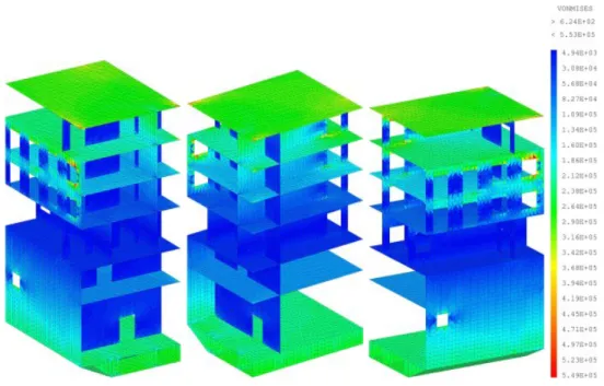
Figure 6: Stress in the structure
[7] J. Mandel, Balancing domain decomposition Communications in Applied Numerical Methods , 9, 233–241 , 1993.
[8] J. Mandel and C. R. Dohrmann, Convergence of a Balancing Domain Decomposition by Constraints and Energy Minimization Numerical Linear Algebra with Applications , 10, 639–659 , 2003.
[9] P. Vanek , M. Brezina and J. Mandel, Convergence of Algebraic Multigrid Based on Smoothed Aggregation Numerische Mathematik , 88, 559–579 , 2001.
[10] P. Vanek , J. Mandel and M. Brezina, Algebraic multigrid based on smoothed aggregation for second and fourth order problems Computing , 56, 179–196, 1996.