O 0 196 7)
THE ARCHITECTURE OF HIGH SPEED TRANSPORTATION
by
Richard David Rush
Submitted in Partial Fulfillment of the Requirements
for the degree of Bachelor of Architecture
at the
Massachusetts Institute of Technology
January 23, 1967
Signature of Author
MuLibaries
Document Services
Room 14-055 1 77 Massachusetts Avenue Cambridge, MA 02139 Ph: 617.253.2800 Email: [email protected] http://Iibraries.mit.edu/docsDISCLAIM ER
The Appendix A section of this thesis contains only
a selection of pertinent pages from the actual
pro-posal made by S.H. Bingham Consulting Engineer.
As a result there are deliberate page omissions.
January 23, 1967
Dean Lawrence B. Anderson
Department of Architecture
Massachusetts Institute of Technology
Cambridge, Massachusetts
Dear Sir:
I submit this thesis, The Architecture
Transportation, in partial fulfillment
Degree in Architecture.
of High Speed
of a Bachelor's
Sincerely yours,
I
Richard David Rush
Signed by: Lawrence B. Andersoo
Dean of the Department
of Architecture
ACKNOWLEDGMENTS
This thesis was only made possible through the good nature
and patience of many people.
Colonel S.H. Bingham (ret.) graciously has supplied the
information concerning his proposal for the high speed
transit system used in this study.
Professor Donald Appleyard has generously given his time
and knowledge especially pertaining to the Modelscope
and closed circuit television.
Professor Robert Hanson
has
provided invaluable information
pertaining to Project Metran and transit systems in general.
Mr.
Leon Groisser has patiently tried to cope with my
ignorance of computer systems.
Professor Maurice Smith was instrumental in giving me the
tools to be able to think about Architecture.
Who can place
enough value on his contribution to my education?
One person stands out as being most helpful to the existence
of this project.
Mr. Nicholas Negroponte has provided the
kind of aid a student needs to be able to cope with his
ignorance.
This thesis could not exist without his help.
I can only offer my gratitude and hopes that this thesis
will justify the help and confidence they so freely
supplied.
ABSTRACT
The written portion of this thesis is divided into
four major parts. The parts are ordered for convenience
of organization and simplicity of comprehension.
The
first section summarizes the program and attempts to justify
it in terms of human experience. Section two explains the
background for the specific project of connecting
George-town Dulles International Airport. The third section
at-tempts to place this project in perspective with the other
projects of similar type being conducted around the world.
The Appendix covers the abstract material in more detail. Of
particular importance is Appendix A which is Colonel Bingham's
proposal for the route taken by the transit system. Of equal
importance is Appendix D which makes an attempt to clarify
the attitude towards simulation techniques.
Part I
Thinking about the Program. Phase One
Technology is leaping ahead of today's architects.
Also leaping ahead of the imagination is the scale of
man's abilities. Architects clearly must expand their
abilities through use of tools. Who is going to provide
these tools? A tool, like a building, is a design. Every
design is only as good as the problem which generates it.
Where does the tool designer get his problem? It must
come from architects and city planners who both speak the
same language as the tool designer.
Normal men have enough problems trying to comprehend
simple human speed and scale problems. But man is going
to the moon! It is a reality. He has the ability to
pro-duce very high speed vehicles. He can travel from Boston
to New York City in twenty minutes. Jet planes are here.
Jet planes mean many things.
They mean that we can travel
at tremendous rates.
They also mean that today's airports
must be modified or rebuilt to handle this new form of
transportation.
Dulles Airport, outside of Washington, D.C. is a very
important example of jet age design. This airport is huge.
It is efficient.
It is also far away from the city. This
means that it could easily take less time to fly across
-2-country than it does to get home from the airport.
Either
the jet is too advanced for other forms of transportation
and we must accept that fact or we must attempt to bring
the forms of land transportation to a speed commensurate
with the scale of the jet.
Engineers can and will design any system of this
nature. The task of an architect is different. Good
architecture and good human experience can not be separated.
A good solution to a mechanical problem satisfies an
engineer but not an architect; nor does it satisfy the
needs of a human being. In addition to being warm, dry,
and protected from the sun when he wishes, the human
being asks for more. He wants a place in which he can
learn. He wants a place which will evoke learning; where
human beings can be alone or with others. He wants to be
able to work or to play. A human being wants to be alive,
all of the time.
Life is either all circulation or no circulation at
all.
If a man is not alive it is because of powers that
are greater than he, or it is because he has decided not
to live.
Existing and living are just two different things.
Man usually does not impose mere existence upon himself.
If he does, he is fighting his most valuable state of
existence.
It is the state of a free and enquiring mind.
A mind that is opened. Tools free a man for other things.
-3-A good environment frees a man's mind for other things.
A jet plane is a good example of man's modern dilemma.
When he steps into a jet plane he, by choice, must
sacri-fice various freedoms which are normally his.
He is
fly-ing at speeds up to six hundred miles per hour at a
height of five miles.
He can not step out and go for a
walk! He cannot open a window. He can only look out of
a window. He must generally keep his seat. Assuming he
is comfortable in his seat, what does he do with his mind?
What do people do in such a situation?
They can go to
sleep.
They strike up a conversation with their neighbor.
They pick up a magazine or a book. They can eat or drink.
If a man chooses not to read, write, converse, or eat he
must satisfy his mind by just sitting and thinking about
doing something else. Otherwise, he is forced into a
dis-continuity of life.
What was life, becomes existence.
The plane ride is over. The jet arrives at Dulles
International Airport, one of the world's most modern air
terminals.
He leaves the plane and travels by "mobile
lounge" to the terminal. From this point he must either
wait for another flight or make arrangements to get to his
destination.
If he has just flown half-way around the
world, it is possible that he might sacrifice great speed
for the relief of an open window and the slow speed of an
automobile. He might even wish to sit in a comfortable
-4-chair, have a good meal, or finish the conversation which
began on the plane. All of these possibilities are
presently available at Dulles Airport.
Let us take, however, another example. A business
man or diplomat has just spent half an hour in the air
from New York City. He has an appointment in the Capitol.
He wants to travel as fast as possible. He still does not
want to sacrifice his life for his existence. He cannot.
In fact he probably wants a reasonable number of choices
of activity in transit.
The demand is great. The D. C. Transit company
com-missions an engineering consultant, S. H. Bingham, to
in-vestigate the engineering possibilities for a high speed
transit system. The system should be fast and as
economical as possible. The transit authorities have also
commissioned an architect, Richard Rush, to study the
aspects of the new system which pertain to environmental
experience. What is the experience of the transit car
itself? How does the passenger get to and from the system?
Where does he sit to wait for the car?
Where does he get
a snack if he is hungry? How does he get his baggage to
and from the car?
Consider the opposite experience. The diplomat is
coming from his office at the Capitol.
Can he enter the
transportation station, but a ticket to New York, check his
-5-baggage, and relax while awaiting his train? Can he
depart directly from his train into the "mobile lounge" and
go directly to his plane? How does this whole system
affect Dulles?
As the architect of this project there are several
chores that present themselves to me.
What kind of spaces
are required for waiting, for buying tickets, for
refresh-ment or buying magazines. The station must have light,
heat, and warmth. It must be dry and comfortable.
If a
passenger so desires, he should have the choice to make
his experience of waiting a visual one.
The architect
must begin to think about colors and textures.
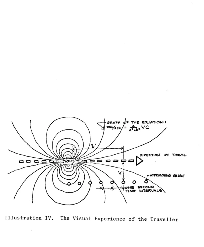
The passenger boards the train. But wait a moment.
What is the architect is trying to design a continuity of
visual experience?
What if he is just trying to understand
the nature of the trip from the stand point of visual
per-ception? The architect must rely upon his imagination.
I
am not satisfied. I need a tool.
What is available?
He
has drawings, perspectives, models, photographs of models.
But the tool plays an important part in determing the final
product. Certainly the more accurate the tool, and the
more skillful the artisan, the more precise the result.
The architect has the responsibility to himself and his
client to be as accurate and as clear as possible.
New tools have been developed for
just
this kind of
-6-investigation and accuracy. The modelscope, a miniature
periscope, has been invented to simulate the experience
of walking through an environment in scale model form.
This device can be coupled with such devices as a video
tape recorder or a 16mm movie camera. At full scale, the
movie camera and time lapse photography have been developed,
largely by city planners, to simulate moving through an
existing environment at various speeds. All of these
tools have been developed and are available to the M.I.T.
student.
A computer program has been designed to simulate, to
a certain extent, the perception of a viewer traveling at
various speeds through an environment. This system can,
at present be applied to the problem.
In the development
stages is a computer program known as "Kludge" that will
be able to make perspective pictures of an imaginary
environment. The unique feature is that this machine is
designed so that a novice with normal intelligence can
operate it.
The area of study of this thesis is high speed ground
transportation. What are the architectural aspects of the
problem and what are the possible solutions.
Simulation
of the experience is an important part cE the study. At
the very least, some attempt will have been made by an
architect to bridge the gap between technological
-7-bilities and the demands of human experience.
A. Phase Two:
I.
Design of a High Speed Transit Station at
Dulles Airport.
a. Plans and Sections.
b. Scale model for Modelscope technique.
II.
Diagrams for design possibilities of
smaller stations on the prescribed route.
a.
Graphical Presentation.
b. Block models for simulation technique.
III. Simulation of a High Speed Transit System
through use of motion pictures.
a. Movie taken along present highways of
the route artificially accelerated to
high speeds to simulate the real
ex-perience.
b. Movie taken with Modelscope of the
ex-perience of traveling through stations
and into the Dulles terminal in particular.
B. Phase Three:
(tentative)
Hopefully phase three will include simulation of
the visual aspects of the trip through use of the computer
programs being developed by Mr. Negroponte and Mr. Groisser.
-8-Part II History of the Project
A. The Route:
Washington D. C. has an interesting history of
attempts to provide a modern transit system. As early as
May of 1959 a 116.17 mile monorail system was proposed by
the D. C. Transit System Incorporated. This report was
admittedly a courageous attempt to thrust a modern transit
system onto the city of Washington.
As a result of the initial rather romantic plans
of the D. C. Transit System, S. H. Bingham a New York
Consulting Engineer was commissioned to do a more detailed
study of the whole problem. During this time the Dulles
International Airport was under construction. Mr. Bingham's
proposal, the one that will provide the basic route for
this thesis, was originally prepared as a "Proposal for a
Demonstration Model."
The plan was rejected by the voters
on a bond issue two years ago.
The system has various advantages as stated by the
proposal.
Some of these which have little to do with
criteria previously mentioned. A high speed transit system
such as the one proposed will keep the highways free and
flexible. This will help to eliminate traffic congestion
and strangulation of the city's vital transport means.
Also
-9-important is the planning consideration that population
and growth generally follows the transportation routes.
This is easily understood. The advantages of such a high
speed transportation system are summarized in the proposal
as follows:
1. High-speed transportation, with a substantial
reduction in travel time.
2.
Dependable Service
3. Low Cost Service
4. Reduction in highway travel would result in
lower capital expenditures for highway
construc-tion.
5. Retention of land areas for tax revenue producing
development purposes.
6. General tax structure favorably affected.
7. Large increases in land values throughout the
area served by the route.
8. The planning and implementation of zoning
restrictions are significantly aided.
9.
New areas added to tax rolls.
The system and route was largely designed with
con-sideration for the economies of construction and in attempt
to provide the most service at least expense. (See Appendix A)
B. Dulles Airport:
It is not the purpose of this study to analyze
-10-every sort of influence that the monorail or high speed
transit systems would have on various building types.
Colonel Bingham presents the projected affect that his
proposal would have on the population expansion. Also
mentioned is the reduction of traffic on the highways
and especially in the city proper.
My special concern is the relation that this kind of
transportation has with an airport, Dulles Airport in
particular. This airport is one of the most modern in
the world. It has been designed specifically for use by
jets.
Perhaps the most unique feature of this airport is the
bus transport system from the plane to the terminal. These
are called Mobile Lounges.
(See illustration I) The
result of this system is a very efficient and fast method
of transporting a passenger to the terminal. Once in the
terminal the whole function of the terminal can be
simpli-fied. All of the airlines can be easily accommodated.
There is less duplication of services. The building is
linear in plan and means that it can be enlarged easily
along its length. The baggage and service floor is
care-fully separated from the waiting functions. One of the
unifying themes of this terminal is simplification and
con-centration of activity. Any building that would be built
near to this one would be expected to work in harmony with
it and remain clear.
(see drawings)
-11-* -v * -- C
IW0
z-AW
r
DULLES INTERNATIONAL AIRPORT
Reproduction taken from Eero Saarinen on His Work
-4I-akv
DULLES INTERNATIONAL AIRPORT
Old System
Aero Gangplank on Fingor
Mobile Lounge System
DULLES INTERNATIONEL AIRPORT
/
-- CI
lull
9
I---I-,Li --- - - - -lir7 F17 u'LH I I \-- I ________ -\ ft ~czzzzE1
. - 5...-- ----
.
ii
~i
ii
v Wv vWWWV
v WW W vuv
VW Wvw V----
---~irnmm
r-
1 U I I IPart III High Speed Transit Systems in Perspective
The reasons for a high speed transit system have been
covered thus far to a large extent. I have accepted Mr.
Bingham's route as the model for my study. I think I
should clarify the issues still more and explain just
where this proposal lies in perspective with other transit
systems that are being designed throughout the world.
An important project that is now under construction
is BART. Bay Area Rapid Transit, in San Francisco.
This
is a billion dollar project.
The entire route covers 75
miles of track and includes transportation at grade, under
water tube, tunneling through mountains, and 31 miles of
elevated trains.
(See illustration II)
A special train
has been designed that travels through all of these
various conditions and at speeds up to 80 mph. Special
care has been taken in this project to plan the individual
stations. A single architect, Donn E. Emmons, was
originally put in charge of this aspect of the project.
He
and his firm made up a "Manual of Architectural Standards"
this
document contains 201 pages of specifications which
each station must comply with. The individual stations
were then commissioned to various firms in the area.
Some specifications are clearly applicable to this project
and have been presented herein. (See illustration III)
-12-Reproduced from Architectural Forum, June 1966
ANTIO-C H
IN
- -
4
LVERM ORE--- CONC ORD ALAMEDA COUNTY
MARIEZ PLEASANT Hi PLEASANTON
- DIABLO TEST WALNUT C EE K
TAK
LAFAYETTE
- CONTRA COSTA COUNTY)
-- -UNION FREMONT
- ,---- . HAYWARD sa m
~
e MILPITAS- --- -- ERKE LEY SAN LORE NZO A,
-- -- - LBANY -L CER ITO SANLEA DR
OAKLAND
-NDO __ SAN JOSE
NO A O IGNACIO --- - -- -
s
-AV*- -- SUNNYVALE
SANTA VENETIA 4-- ---- - - - ---- -
-SAN RAFAEL
g-
--COPTE MADERA a-s - -- PALU ALTO
MILL VALLEY _-- -- -- g REDWOOU CIT Y
SAUS IT - I # AN MA TEO
- BURLINGAME
04e 60 MILLBRAE --- DALY CITY SAN FRANCISCO
-- -- ---- --- - -SAN BRUNO 0 5 10
l
MILES- - --- -- --- - FIRST STAGE PROGRAM
-
~ ~~~~
- -1 --- - - - o m II P SSIBLE FUTURE EXTFNSIONSThe whole project is the obvious predecessor for such a
project as the one I am associating with. Clearly the
architect has played an important role in the development
of BART.
The Japanese have recently spent much time
experi-menting with high speed monorail systems.
The system
used in the monorail was the Hitachi-Alweg System. This
is the world's longest monorail lien.
It links
Hamamatsucho, in the heart of Tokyo, with Tokyo International
Airport at Haneda. The line is 13.1 kilometers in
length and has been built largely for the purpose of
shortening the one hour automobile trip to a traveling
time, by monorail, of fifteen minutes.
Some thought has been given to extending the monorail
system which is presently located in the center of Seattle,
Washington. The Seattle-Tacoma Airport is nearly ten miles
from the center of the city.
Careful reports have been
made evaluating the existing monorail system by Mr. Eckse
of the University of Washington. The presentation is quite
clear and complete.
It is not clear why the project has not
been continued. The immediate reason given is the highway
which has been recently constructed from the center of the
city to the airport. As has been discussed already, this
is only a temporary solution to the problem and relies on
old methods that cannot really solve the problem.
-13-Among the various transit systems which have been
designed for the same general purpose as the one I am
dealing with, much of the work has been done with
mono-rails or elevated trains in mind. I believe that the
Bingham system is the best that has been developed so
far for these purposes. Of special important is the
transitional factor of being able to easily combine with
the standard form of subway rail transit.
(See Appendix
B and C)
At even larger distances, greater speeds can be
reached. Recently the Japanese have constructed the
Tokaido Line, a high speed transit system that encompasses
all of the major Japanese cities--Tokyo, Yokahoma, Nagoya,
Kyoto, Osaka, and Kobe.
The train reaches speeds up to
125 mph and is serving to unite the country into a vast
megapolis.
The most recent development has been developed in
France by the Engineer-Designer Jean Bertin. This train
rides on a cushion of air and, with a jet booster for power,
has been tested at speeds up to 250 mph. He has recently
made a trip to the United States in hopes of developing a
system that could cut travel time between New York and
Washington to an hour and a half.
APPENDIX A
The following is a selection of pertinent
pages from the actual proposal made by
S.H.Bingham Consulting Engineer for
the D.C. Transit System.
-15-PROPOSAL FOR A DEMONSTRATION MODEL
of
A CONTROLLED HIGH-SPEED SUPERAIL
TRANSIT SYSTEM FOR MASS TRANSPORTATION
WASHINGTON, D. C. to DULLES INTERNATIONAL AIRPORT
PREPARED BY D.C. TRANSIT SYSTEM, INC. WASHINGTON, D.C.
In collaboration with
COLONEL S. H. BINGHAM, (AUS RET.) CONSULTING ENGINEERS AND ARCHITECTS
NEW YORK, NEW YORK
©
Copyright January 1962 byD. C. Transit System, Inc. and
Colonel S. H. Bingham, (Ret.)
All Rights Reserved
The text of this publication or any part thereof may not be reproduced in any manner whatsoever without permission in writing from the author.
14
ROUTE AND TERRITORY SERVED
The controlled high-speed mass transportation system, details of which are given in this report, would fol-low a route which has a most advantageous placement in rela-tion to construcrela-tional economy and singular utility for public service.
Georgetown-Glen Echo Area
This route, commencing with a tentative terminal in Georgetown, would follow the scenic D. C. Transit right-of-way to the Glen Echo area, a distance of 5. 65 miles. Through-out this portion of the rThrough-oute, well-established areas of popula-tion would be served. These areas include 0. D. zones 17, 16,
13, 12 and 11, which would be directly served, as they border the right-of-way. The bordering zones, 28, 26, 23 and 22,
should benefit to a lesser degree from the high-speed mass transit service which the route would provide.
From the Glen Echo area the route would cross the Potomac River to the Government Reserve land near the site of the C.I.A. building. A fortunate factor is the existence of a
ravine leading from the southern bank of the river to the higher
15
land in the governmental area. The existence of this ravine will substantially reduce the cost of construction for this section.
The route in this area would serve the transit
needs of the C.I.A. and other governmental agencies which now are, or will be, established in this Reserve land.
The McLean Area
The route would then continue over the median
strip of the McLean bypass to the growing community of McLean, which it would effectively serve. The route distance from the Glen Echo area to McLean is 4. 50 miles.
Dulles International Airport
From McLean the route would follow the median strip of the Dulles International Airport access highway, a distance of 15. 75 miles, a total length of route from George-town to the Airport of 25. 90 miles.
Between McLean and the Dulles International Air-port, the route would be a vital factor in the vigorous economic growth of the numerous development enterprises which today are reported to be in various states of planning.
16
The terrain is favorable to construction of the sys-tem; the crossing of the Potomac River presents no engineer-ing problem of moment.
Throughout the land areas traversed, long sections of the route are essentially tangential; wide radius curves are possible where such design treatment is necessary. Maximum grades, mostly of very short duration, are not expected to ex-ceed 4 percent. Such gradients are limited in number and readi-ly negotiable.
A most important and economically attractive fea-ture which greatly favors construction of this proposed demon-stration model of a controlled high-speed mass transit system is that its construction would involve no purchase of property, no easement, and no property condemnation. Consumation of the project would be dependent upon agreements mutually nego-tiated between all the governing agencies involved and the responsible proponents of the proposed system.
Extensions and Additions
Washington, D. C. , the Nation's Capital, is also the Nation's showcase and warrants the most modern and pro-gressive installations. The controlled high-speed mass transit
17
system presented herein is not limited to the Dulles Interna-tional Airport route as an isolated installation. Its economic and utilitarian merits justify its serious consideration in a greater field of application.
Numerous streets and highways in the District of Columbia are provided with median strips which lend them-selves admirably to the rapid construction and operation of this transit medium. An extensive system of high-speed mass transit facilities is therefore possible over existing streets and highways with no new roadway construction necessary.
These street and highway corridors serve the areas of major population density, - the areas, therefore, in greatest need of high-speed mass transportation.
The constructional economies which the principle of overhead Superail operation makes possible are coupled with a capability for underground placement, in specific and limited areas where compelling circumstances are believed
21
Established Communities
The route as outlined in Chapter II traverses a tributary area containing a number of existing community centers, the growth of which would be stimulated by the avail-ability of a controlled high-speed mass transit system. These are:
1. The Georgetown-Glen Echo Area
2. The Government Reserve Land-C.I.A. Building 3. McLean and environs
4. Herndon and environs
Population Growth Trends
1. The Georgetown-Glen Echo Area
That portion of the route which follows the scenic D. C. Transit right-of-way from Georgetown to the Glen Echo area in Maryland, passes through corridor 0. D. zones 17, 16,
13, 12 and a portion of O. D. zone 11. The route also lies in close proximity to 0. D. zones 28, 26, 23 and 22, which border the corridor 0. D. zones. The corridor 0. D. zones 17, 16,
13, 12 and 11, and to a lesser extent the bordering zones, were the areas which provided the riders for the street car operations.
30
These annual totals are equivalent to an attendance
during a six-month season of 20, 000 per day in 1965 and 40, 000 per day during 1980.
In the evaluation of these totals, consideration must be given to the fact that during 1965 an estimated number of
10, 300, 000 and in 1980 an estimated number of 14, 300, 000 visi-tors of all categories will visit the Nation's Capital. A large percentage of these are in "holiday" mood.
The existing Glen Echo Amusement Park attracted approximately one million visitors over a five-month period
dur-ing 1960, or approximately 7, 000 per day.
Dulles International Airport
The operation of a modern airport requires a multi-tude of activities which involve people who have considerable diversity of interests. These may be classified as follows:
(a) Passengers
(b) Visitors accompanying or meeting passengers (c) Employees
(d) Sightseers
(e) Mail Trucks
(f) Supply Trucks
In any determination of the percentage of airline pass-engers who might wish to patronize the controlled high-speed mass
31
transit system it is necessary to consider them in certain group classifications, as follows:
I. Local - Those who originate or terminate in the Washington, D. C. area.
II. Transfer - Those who transfer to other planes at the Dulles International Airport. III. Those who use the Dulles International
Air-port as a stopping point en route to and from other destinations only because their aircraft makes a stop there.
Group I, therefore, is the prime source from which patrons of the high-speed mass transit system may be attracted.
In quite a limited way, Group II could provide some patronage. It is considered appropriate, however, to regard
Groups I and II as constituting the total outgoing or incoming passenger population.
Experience has shown that an airport which handles approximately 7, 500 arriving and departing passengers on a typical day can be assumed to have about 3, 700 visitors and sightseers and 3, 500 employees.
32
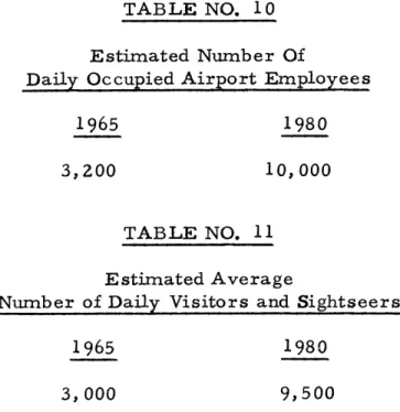
It has been estimated that the growth of traffic at the Dulles International Airport will involve the following totals
of enplaning and deplaning passengers:
TABLE NO. 8
Dulles International Airport Estimated Yearly Passenger Volumes
Domestic International Total
I1st year 1,265,000 305,600 1,570,600
5th year 2,235,600 384,000 2,619,600
15th year 5,525,000 580,000 6,105,000
If it is assumed that the Dulles International Airport will commence operations in 1962, the projected values for total passengers, employees and visitors would be as follows:
Domestic Inte rnation Totals
ume at the
TABLE NO. 9
Dulles International Airport Projected Yearly Passenger Volumes
1965 1980
1,855,000 5, 525, 000
al 352,640 580,000
2,202,640 6,105,000
These values indicate an estimated average traffic vol--Dulles International Airport of 7, 500 daily passengers
33
in 1965 and 20, 000 daily passengers in 1980.
TABLE NO. 10
Estimated Number Of
Daily Occupied Airport Employees
1965 1980
3,200 10,000
TABLE NO. 11 Estimated Average
Number of Daily Visitors and Sightseers
1965 1980
3,000 9, 500
With the use of the jet airplane, distant cities can be reached within minutes or hours, and air speed capabilities are still in the development stage. Completely out of harmony, and to a degree nullifying the speed advantages otherwise gained,
existing means of ground travel to and from the airports
present a picture of frustration. In many instances the time con-sumed in ground travel to and from airports equals the time spent
in flight.
The high-speed mass transit system herein discussed would connect the airport and the central city in approximately
34
25 minutes running time compared to a required time by exist.-ing media of transit estimated to be in excess of 45 minutes.
Air Mail and Airborne Parcel Post
A potential source of revenue for this demonstration model of controlled high--speed transit would be developed through the transport of mail, parcel post and other related services be-. tween the airport and a mutually acceptable location.
Cars of special design will be provided for this pur-pose and will permit pallet and basket types of mail containers to be carried. Related commodities which have miscellaneous classifications may also be moved.
Advertisements and Concessions
Traditional forms of revenue for transit vehicles and station areas which would be sources of revenue for the controlled high-speed mass transit system are advertisements and concessions.
Visitors, Conference and Convention Attendance
Washington, the National Capital, is a powerful magnet which draws visitors from all over the nation and points
35
beyond. In addition to its annual influx of tourist visitors, it also acts as a host city to numerous conferences and conven-tions. Their potential as patrons of the controlled high-speed mass transit system is extremely high. Available figures on the annual totals of these groups are quite accurate.
These statistics show the following totals for 1960. Projections of estimated rate of increase to 1980 are included:
TABLE NO. 12
Annual Visitors to the National Capital
1960 1965 1980 Delegates to Conferences and Conventions 450,000 550,000 750,000 School Students 600,000 800,000 1, 200, 000 Sightseeing Visitors 6, 200, 000 8, 950, 000 12, 350, 000 7, 250,000 10,300,000 14, 300, 000
Summation of Mass Totals
A summation of the segregated population totals con-tained in the preceding tables, reveals, in effect, the mass total or population pool from which the revenues of the controlled high
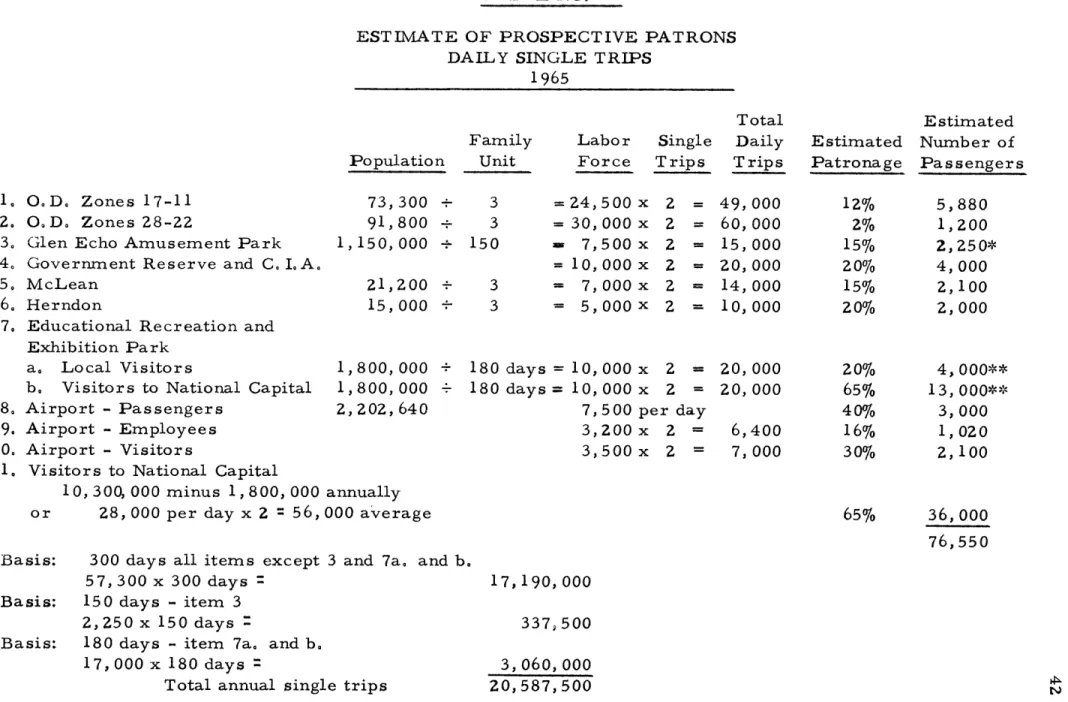
TABLE NO. 14
ESTIMATE OF PROSPECTIVE PATRONS DAILY SINGLE TRIPS
1965
O.D. Zones 17-11
O. D. Zones 28-22
Glen Echo Amusement Park
Government Reserve and C. I. A.
McLean Herndon
Educational Recreation and Exhibition Park
a. Local Visitors
b. Visitors to National Capital
Airport - Passengers
Airport - Employees
Airport - Visitors
Visitors to National Capital 10, 300, 000 minus 1, 800, 000 or 28,000 per day x 2
=
56, Population 73,300 + 91,800 1, 150, 000 21,200 + 15,000 + 1,800, 000 + 1,800,000 + 2, 202, 640 Family Unit 3 3 150 3 3 180 days 1 180 days 1 Labor Force 24, 500 30, 000 7,500 10, 000 7, 000 5,000 0, 000 0, 000 7,500 3,200 3,500 Single Trips x x x x x x x x pe x x 2 2 2 2 2 2 2-= 2-= r day 2-2-= Total Daily Trips 49, 60, 15, 20, 14, 10, 000 000 000 000 000 000 20, 000 20, 000 6,400 7, 000 annually 000 averageBasis: 300 days all items except 3 and 7a. and b.
57, 300 x 300 days
Basis: 150 days - item 3
2,250 x 150 days
Basis: 180 days - item 7a. and b.
17, 000 x 180 days
=
Total annual single trips
Estimated Patronage 12% 2% 15% 20% 15% 20% 20%
65%
40%16%
30%65%
Estimated Number of Passengers 5,880 1,200 2,250* 4, 000 2,100 2,000 4, 13, 3, 1, 2, 000** 000** 000 020 100 36,000 76,550 17,190,000 337, 500 3,060,000 20, 587,500* Deduct 337, 500 if an educational recreation and exhibition park is in operation.
** Deduct 3, 060, 000 single trips if an educational recreation and exhibition park is not in operation.
10 2. 3. 4. 5. 6. 7. N or- V
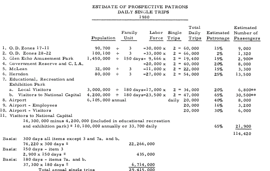
4NNNNNff0w=ww---TABLE NO. 15
ESTIMATE OF PROSPECTIVE PATRONS DAILY SINGLE TRIPS
1980 Population Family Unit Labor Force Single Trips Total Daily Trips Estimated Patronage Estimated Number of Passengers O. D. Zones 17-11 O. D. Zones 28-22
Glen Echo Amusement Park Government Reserve and C. I. A. McLean
Herndon
Educational, Recreation and Exhibition Park
a. Local Visitors
b. Visitors to National Capital
90,700 100, 100 +-1,450,000 + 32,000 80,000 + 3,000,000 + 1 4,200,000 + 1 3 =30, 3 =33, 50 days= 9, =20, 3 =11, 3 =27, 000 000
666
000 000 000 x x x x x x 80 days=17, 000 x 80 days=23,500 x Airport 6,105, 000 annual d Airport - Employees Airport - VisitorsVisitors to National Capital
14, 300, 000 minus 4,200, 000 (included in educational recreation
and exhibition park)
=
10, 100, 000 annually or 33, 700 dailyBasis: 300 days all items except 3 and 7a. and b.
74,220 x 300 days
Basis: 150 days - item 3
2,900 x 150 days
Basis: 180 days - items 7a. and b.
37, 300 x 180 days ::
Total annual single trips
22,266,000 435,000 6,714,000 29,415, 000
* Deduct 435, 000 single trips if an educational recreation and exhibition park is in operation.
** Deduct 6, 714, 000 single trips if an educational recreation and exhibition park is not in operation.
1. 21. 3. 4. 5. 6. 7. 8. 9. 10. 11. 2 2 2 2 2 2 60,
66,
19, 40, 22, 54, 000 000 400 000 000 000 000 000 000 000 0009,
1, 2, 8, 3, 13,6,
30, 8, 3,6,
15% 2% 15% 20% 15% 25% 20%65%
40%16%
30%65%
000 320 900* 000 300 500 800** 5 00** 000 200 000 2 = 34, 2 = 47, aily 20, 20, 20, 21, 900 114, 42054
TABLE NO. 16
CONDITIONS OF OPERATION AND CAR REQUIREMENTS
Daily Passengers Single trips one--way Maximum Hour
15 percent of 38,275* Car Capacity - Passengers Maximum hour train trips
necessary with 4-car trains Headways - Minutes
Number of cars required
38, 275 5, 740 100 15 4 60
Spare cars required 5
15 train trips x 400 passengers per trip 15 train trips x 4 cars per train = 15 train trips with 4 minute headways
6, 000 passengers 60 cars
60 minutes
* The volume of passenger movement during the maximum hour has been estimated as representing 15 percent of the one-way total of 38,275 or 5,740 passengers. This system, with the full safety protection provided by the modern signal system, is capable of carrying 45,500 passengers per hour in each direction with 10-car trains operating at 2-minute intervals. The system is also capable of operating at 90-second intervals if required.
61
the train schedule, the automatic dispatcher will select the train to be dispatched, the route over which the departing train must operate, set the route, switches and signals, illuminate the starting lights, close the doors and start the train.
Each station will have a programmer that will regulate the length of station stops, in accordance with the time of day, depending on whether it is rush hour, evening, non-rush hour, etc.
As the train approaches a station, it will be brought to a safe predetermined speed and the head end of the train will
stop at a preselected point, plus or minus 3 feet.
Departure time will be indicated by an audible alarm and the doors, which are interlocked with the controller, will be closed automatically permitting the train to proceed on its way.
As previously mentioned, the supervisory control system is combined with the signal system to form a single sys-tem.
The supervisory control is subjected only to local conditions without any consideration of conditions that may pre-vail on any other part of the railroad or route control system.
66
STATIONS AND PARKING AREAS
Station Locations
The proposed route would be provided with two terminal stations and five intermediate stations, making a total of seven.
A tentative inner terminal station would be lo-cated in Georgetown; the outer terminal station would be located at Dulles International Airport.
The five intermediate stations would be located in the following areas:
Brookmont Glen Echo C. I. A. Area McLean Herndon Station Arrangements
The general arrangement and appearance of the stations are shown in Fig. 7, Fig. 8 and Fig. 9.
A mezzanine floor, beneath the platform area, would be reached from street level by passageways on both
67
The mezzanine floor would accommodate the nec-essary facilities for change making, turnstiles and public com-fort rooms. The platforms overhead would be reached by speedwalks and stairways.
It is considered that an island type platform would most effectively serve this controlled high-speed mass transit operation. These platforms would be provided with weather-proof enclosures for the protection of waiting passengers during inclement weather.
The exposed sections of the platforms would be covered with structural, protective canopies of modern design.
Provision has been made in the cost estimates for platforms having a length of 300 feet, which would permit the operation of trains with consists of five 50-foot cars. The design of the platforms permits extensions to be added as the need develops.
Station Lighting
The mezzanine and platform areas would be illum-inated by fluorescent lamps using a continuous strip-type of fixture. These would provide an illumination level for these areas of not less than 20-foot candles.
68
Station Advertising
Revenue-producing advertising displays would be made possible through the provision of suitable panels on ap-propriate wall spaces within the mezzanine and platform areas.
Terminal Stations
The terminal station at the Dulles International Airport would be located and constructed in accordance with
the regulations of the governing authorities.
As a service of public convenience, it is highly desirable that this station should be located in close proxim-ity to the main concourse of the airport terminal building. If such an arrangement should gain favor it would be possible to operate the train into the terminal building at a below-ground level.
From the platforms, speedwalks would carry the passengers directly into the main concourse of the airport
terminal building.
Automobile Parking Areas
The provision of automobile parking areas at sta-tion locasta-tions has proved to be an effective means of increasing
69
the usage of public transit facilities. This so-called "park and ride" convenience is becoming increasingly popular and will be made available wherever possible. In addition to this, the drive and ride practice is growing in importance as a rev-. enue producer, particularly throughout such comparable areas as those considered for this route.
In a drive and ride operation, the transit passen-ger is driven to or met at the station by a member of the fam-ily using an automobile. This is attractive to the transit rid-er as it provides him with a speedy ride to his destination and it makes the automobile available to the family during the day.
Local Feeder Buses
In order to increase the revenue from areas beyond walking distance of the Superail transit stations, a system of feed-er buses has been considfeed-ered. The provision of routes and vehi-cles to serve the areas in the vicinities of the enumerated sta-tions is a matter of planning.
Feeder Buses to Central City Area
Until the controlled high-speed mass transit system is extended into the central city area it will be necessary to operate a
70
feeder bus service between the tentative terminal at George-town and a designated area or areas in the central city. Cost estimates for this operation have been included in the estimated total costs.
COLS.H.BINGHAM (RET)
PERSPECTIVE
OF A TYPICAL WAYSIDE STATION
JANUARY 15, 1962
I
H
ALTERNATE I
PLAN
. ...C
ROSS -SECTION
*~~~~1I
PLAN
TYPICAL
STATION ARRAN GEMENT
FIG
A
1
--
~1~- -*h
I V U,K
.iF 4 4 ka. v z aw, 11,IL
ALTERNATE 3
PLAN
CROSS
-
SECT
TYPICAL
STATION
ARRANGEMENT
APPENDIX B
The following is a selection of pertinent
pages from the actual presentation by
S.H.Bingham of his transit car system.
-16-COLONEL S. H. BINGHAM. (RET.)
CONSULTING ENGINEERS 109 EAST 35TH STREET
NEW YORK, N. Y. 10016
MURRAY Hi.L. 3-0100
Tle Bingham System A New Concept of High-Speed "Fail-Safe" Mass Transportation
Designed, Engineered and Patented By
Colonel S. H. Bingham, (Ret.) Consulting Engineer
April 15, 1966
Q Copyright 1962, 1963, 1964, 1965 and 1966 by Colonel S. H. Bingham, (Ret.)
All Rights Reserved
The text of this publication or any part thereof may not be reproduced in any manner whatsoever without
Colonel S. H. Bingham, (Ret.) 7
The new and meritorious features incorporated in the design and engineering configurations of the Bingham'System in-clude the following capabilities, a substantial number of which are not universally common to other media of mass transportation:
a. It is a truly high-speed system, due in part to more expeditious switching procedures and to less need for speed restriction on curves. It is, however, fully adaptable to any lower range of speed requirements. b. It is not a monorail system. Actually, it is a
dual-rail, multi-purpose system employing pneumatic tires in combination with conventional steel wheels, Drawing No. 1311 -G, or conventional steel wheels on steel rails. c. The structure necessary for its operation, which can be
either prestressed concrete or steel, is dimensionally smaller than those required by other proposed systems. d. Due to its smaller overhead structure less shadow is
cast, Drawing No. 1310-B.
e. Its structural dimensions underground are less than
those of other systems, as shown in Drawing No. 1310-B. f. The riding surface of the beam of the Bingham System is
adjustable as shown in Drawing No. 1311-G, permitting superelevation to be obtained on curves without the need for precise beam twisting during fabrication. Later ir-regularities or settlements of the structure can be cor-rected through adjustment without involving costly struc-tural r ealignments.
g. Conventional dual-rail switching is employed, Drawing No. 1350, and reverse running is secured. The neces-sary time-consuming and cumbersome openings of track sections and dangerous gaps in structure required by the monorail principle, either suspended or overrunning, are eliminated in the Bingham System.
- - --- ~-- -~
Colonel S. H. Bingham, (Ret.) 8
h. Positive protection is assured inthe event of any tire blow out or deflation on either the supporting or guiding wheels, Drawing No. 1311-G.
i. Higher rates of braking than those normally achieved at present are made possible through the use of a novel patented arrangement whereby maximum multiple braking forces can be applied, especially for trains operated at high speeds, which provide for the rapid stopping of trains with safety, in less than one-third the distance now re-quired by trains operated at high speeds,
j.
Cars have lower center of gravity and superior stability under normal or stress conditions, Drawing No. 1351. A normal car floor arrangement is provided, no wheels project into the interior of the car.k. Normal dual-rail operation of cars, at ground level, in inspection sheds and lay-up yards is possible. No ob-structive beams are necessary, due to ability to utilize steel wheels either during switching, or with steel wheel on steel rail operations. Existing monorail systems, either suspended or overrunning, cannot function in this manner.
1. Vitally important features incorpo rated in signal track circuitry of the Bingham System, for which patents have been granted, prevent the possibility of trains colliding
into the rear end of a stalled train. Systems employing the monorail principle with pneumatic tires, lack this essential safety feature,
m. The cars of the Bingham System are fully compatible with automatic operation should such a procedure be considered. n. The unique design and engineering features of the Bingham
System make possible the operation of a high or medium speed, multi-purpose, "fail-safe" mass transportation system.
11 Colonel S. H. Bingham, (Ret.)
d. Loads resulting from longitudinal forces de-veloped by the acceleration, running and brak-ing Of the trains .
, Thermal forces , which have been guarded against by the appropriate placement of px-pansion joints.
2.3 Basis for Design
Details for the loading analysis upon which the structural design has been based are given below:
Basic Car Data Length
Height - car plus beam
Width
Weight, loaded
Distance between trucks Wheel base 60' 15'-2'' 10' 75, 000 lbs. 42' 4.8' Structure Data
Clearance above ground
Height of center of wind pressure above ground footing
14'
24'
General Design Factors Impact coefficient
Wind load
Lateral gravity component Lateral earthquake forces Maximum deflection allowed Maximum torsional deflection
allowed
Weight of supporting and guiding rails 25% 15 lbs . per sq. ft. 10% 10% 1/800 of span .03 degree /ft. 200 lbs./ft.
I
Colonel S. H. Bingham, (Ret.) 1
2. 4 Supporting Columns
Several configurations have been developed for use in the fabrication of the supporting columns, Their dimensions at the founda-tion level require substantially less ground area than convenfounda-tional overhead structures. It was considered that with towers 14' in height, where placed on tangent alignment, a spacing of 70' would be aesthet-ically acceptable and would also provide structural economies. Piling would be used where soil pressures are not adequate to sustain loads.
2. 5 Beams
The beam would be fabricated from prestressed concrete, steel or a combination of both. A design objective, which was realized, was to develop a beam section having minimum dimensions and weights compatible with the loading stresses to which it would be subjected. The beam cross -section therefore will achieve the maximum moment of inertia in both the vertical and horizontal direction for minimum weight provision.
The method employed of associating the beam with support-ing columns, Drawsupport-ing No. 1336, makes possible a structure with a lower overall height, including the car height. As mentioned earlier,
12
Colonel S. H. Bingham, (Ret.) 13
this particular feature of the proposed design develops a loading mo-ment at the base of the supporting column, lower than that which other systems have been able to attain.
2.6 Adjustable Rails
The measure of car riding comfort and its requirements for maintenance depend upon the lateral and vertical alignment of the surface upon which its supporting wheels operate. If no adjustment of this surface is provided,, the ultimate end result will be rough rid-ing and high maintenance. With systems employing guide wheels, the rails upon which these wheels run must also be provided with means for lateral adjustment.
The Bingham System provides for adjustment of the rails, both supporting and guiding, and these adjustable features have been integrated with the beam configuration in a composite design. Pro-vision has been made in the supporting and guiding rails to allow for variable adjustments within the range of plus or minus 2".
It is not realistic to expect that adjustment of the running surfaces would not be necessary. During construction variations in the alignment of the structure sections, either vertical or lateral or both, are reasonable assumptions.
Colonel S. H. Bingham, (Ret.)
adjustment which has been developed for the Bingham System. This is another important feature of this new design as it makes possible the fabrication of the beam at lower costs and with production time
reduced.
Z.7 Current Carrying Contact Rails
The guiding rails have been designed to serve a dual pur-pose: to guide the car and to carry electrical energy for the electrical traction motors and the car auxiliary equipment.
2,8 Shadow Cast by Structure
A rapid transit system operating on an overhead structure would cast three shadows:
1. The beam,
2. The supporting column, 3. The passing train.
The shadow cast by the beam would be continuous, that cast by the supporting columns intermittent, governed by the spacing and dimensions of the columns, and the shadow cast by the passing train
would be periodic.
The surface area brought into shadow by the beam is a matter for critical consideration. Due to its arrangements and
smaller dimensions., the extent of the shadow cast by the structure 15
Colonel S. H. Bingham, (Ret.) 16
the Bingham System is substantially less than that of other systems, a feature which offers both aesthetic and economic advantages. A comparison of the areas brought into shadow is shown in Drawing
Colonel S. H. Bingham, (Ret.)
3. 7. 1 Braking
Train deceleration will be accomplished by dynamic braking supplemented by a modern system of disc brakes.
For normal service conditions, automatic dynamic braking would be provided with selective rates up to 3 mphps. When dynamic braking begins to fade, its braking effort would be supplemented by the disc brakes to bring the train to a stop and hold it in a stationary position.
Emergency braking would be accomplished at higher rates through the immediate operation of the dynamic and disc braking systems acting in unison. The dynamic braking control would function in response to the position of the single handle
controlling both the dynamic and the disc brakes.
3. 7. 2 Braking of High-Speed Steel Wheeled Trains In the operation of vehicles or trains equipped with steel wheels at speeds of 150-225 miles per hour or higher, spe-cial provision must be made for the safe braking of the train down to lower speeds and, ultimately, to a standstill. Due to the low level of adhesion between the steel wheels and the rails, which grows lower as train speeds increase, the initial rate of retarda-tion applied through the steel wheels either mechanically or
Colonel S. H. Bingham, (Ret.) 30
electro-dynamically must be at a comparatively low level to guard against wheel locking.
The Bingham High-Speed System, a development of the Bingham System, includes a novel arrangement, for which a patent has been granted, whereby additional braking effort can be applied to vehicles or trains, especially when operated at high speeds, through the use of the guiding or stabilizing wheels, which can be effected independently of or in combination with the application of the braking effort to the main or running wheels of the vehicle. Thus, the maximum braking forces for the train can be applied. This adequate multiple braking effort provides for the rapid stop-ping of trains with safety, within one-third the distance now re-quired by trains operated at high speeds.
3. 7. 3 Car Speed - Acceleration and Maximum Speed Relationships.
The questions of acceleration and the maximum speed of which a transit vehicle or train of the so -called monorail type is capable have been confounded by claims, the majority of which, are imaginative and unrealistic.
A system which is intended to function as a medium of mass transportation with stations spaced one mile apart, or even less, has fundamentally different conditions of acceleration and