Publisher’s version / Version de l'éditeur: Technical Report, 2010-05-01
READ THESE TERMS AND CONDITIONS CAREFULLY BEFORE USING THIS WEBSITE. https://nrc-publications.canada.ca/eng/copyright
Vous avez des questions? Nous pouvons vous aider. Pour communiquer directement avec un auteur, consultez la
première page de la revue dans laquelle son article a été publié afin de trouver ses coordonnées. Si vous n’arrivez pas à les repérer, communiquez avec nous à PublicationsArchive-ArchivesPublications@nrc-cnrc.gc.ca.
Questions? Contact the NRC Publications Archive team at
PublicationsArchive-ArchivesPublications@nrc-cnrc.gc.ca. If you wish to email the authors directly, please see the first page of the publication for their contact information.
NRC Publications Archive
Archives des publications du CNRC
For the publisher’s version, please access the DOI link below./ Pour consulter la version de l’éditeur, utilisez le lien DOI ci-dessous.
https://doi.org/10.4224/17210695
Access and use of this website and the material on it are subject to the Terms and Conditions set forth at
Modeling and Simulation of Ship Manoeuvring with Azimuthing Podded Propulsion Systems : An Interim Report for Fiscal Year 2009-2010
Lau, Michael
https://publications-cnrc.canada.ca/fra/droits
L’accès à ce site Web et l’utilisation de son contenu sont assujettis aux conditions présentées dans le site LISEZ CES CONDITIONS ATTENTIVEMENT AVANT D’UTILISER CE SITE WEB.
NRC Publications Record / Notice d'Archives des publications de CNRC: https://nrc-publications.canada.ca/eng/view/object/?id=fb66ce2c-bdbf-48dc-82a1-25d5f3cffcdc https://publications-cnrc.canada.ca/fra/voir/objet/?id=fb66ce2c-bdbf-48dc-82a1-25d5f3cffcdc
DOCUMENTATION PAGE
REPORT NUMBER
TR-2010-10
NRC REPORT NUMBER DATE
May 2010
REPORT SECURITY CLASSIFICATION Unclassified
DISTRIBUTION
Unlimited
TITLE
MODELING AND SIMULATION OF SHIP MANOEUVRING WITH AZIMUTHING PODDED PROPULSION SYSTEMS:
AN INTERIM REPORT FOR FISCAL YEAR 2009-2010 AUTHOR(S)
Michael Lau
CORPORATE AUTHOR(S)/PERFORMING AGENCY(S)
Institute for Ocean Technology, National Research Council, St. John’s, NL
PUBLICATION
SPONSORING AGENCY(S) Transport Canada IMD PROJECT NUMBER
42_2409_16
NRC FILE NUMBER
KEY WORDS
OSIS, manoeuvring, ice, simulation, pod, pressure
PAGES vi, 16 FIGS. 9 TABLES 1 SUMMARY
This report summarizes the results obtained in the first year of a three-year collaborative project between the NRC Institute for Ocean Technology and the Memorial University of Newfoundland’s Centre for Marine Simulation under its “Modeling and Simulation of Ship Maneuvering with Azimuthing Podded Propulsion
Systems Project.” The project is funded by Transport Canada of the Government of
Canada through its Marine Safety Program. The completed work elements are described and the important results to date are highlighted. This report also provides a brief summary of the accompanying reports and papers generated for this project. ADDRESS
TEL.
National Research Council Institute for Ocean Technology P. O. Box 12093, Station 'A'
St. John’s, Newfoundland, Canada A1B 3T5
National Research Council Canada
Institute for Ocean Technology
Conseil national de recherches Canada
Institut des technologies océaniques
MODELING AND SIMULATION OF SHIP MANOEUVRING WITH
AZIMUTHING PODDED PROPULSION SYSTEMS:
AN INTERIM REPORT FOR FISCAL YEAR 2009-2010
TR-2010-10
Michael Lau May 2010
ABSTRACT
This report summarizes the results obtained in the first year of a three-year collaborative project between the NRC Institute for Ocean Technology and the Memorial University of Newfoundland’s Centre for Marine Simulation under its “Modeling and Simulation of Ship Maneuvering with Azimuthing Podded Propulsion
Systems Project.” The project is funded by Transport Canada of the Government of
Canada through its Marine Safety Program. The completed work elements are described and the important results to date are highlighted. This report also provides a brief summary of the accompanying reports and papers generated for this project.
ACKNOWLEDGMENTS
The investigations presented in this report were funded by Transport Canada. The Marine and Ocean Engineering Research Institute (MOERI) of Korea provided the ARAON model for testing. The Marine Institute’s Centre for Marine Simulation provided access to its simulator for model implementation and validation.
The author wishes to sincerely thank Mr. Victor Santos-Pedro, Director of Design Equipment and Boating Safety of Transport Canada Marine Safety, for funding this work. Dr. Ayhan Akinturk provided general assistance in model test and advised on the development and implementation of the propulsion model. Ms Renee Boileau provided editing of the report. Their support is gratefully acknowledged.
TABLE OF CONTENTS
ABSTRACT... III ACKNOWLEDGMENTS ...IV LIST OF FIGURES ...VI LIST OF TABLES...VI
1 INTRODUCTION ... 1
2 WORK PLAN ... 2
3 PHASE 1 COMPLETED TASKS AND RESULTS... 3
3.1 Work Element 1: Literature Review and Database Development... 3
3.2 Work Element 2: Model Tests of the Icebreaker ARAON... 4
Task 2.1: Model design and fabrication ... 4
Task 2.2: Model testing... 6
3.3 Work Element 3: Preliminary pod model development... 7
Task 3.1: Analysis of USCGC Mackinaw model test pod data... 8
Task 3.2: Pod model development ... 9
Task 3.3: Model Integration to OSIS and Polaris ... 12
4 LIST OF REPORTS AND PUBLICATIONS ... 14
5 RECOMMENDATIONS FOR FUTURE WORK ... 15
LIST OF FIGURES
Figure 1. Bow view of the model ARAON (IOT Model 850) ...5
Figure 2. The pods installed on the model ...5
Figure 3. The inner structure of the model pod ...6
Figure 4. The global load measuring assembly...6
Figure 5. Turning circle run in level ice ...7
Figure 6. Experimental set-up of the USCGC Mackinaw model in the IOT ice tank...9
Figure 7: Comparison of predictions from OSIS and Polaris simulations for turning in open water: (a) Turning diameter (b) Steady speed (OSIS with IOT Pod at 130.5 rpm and Polaris with Mackinaw pod at 180 rpm) ...11
Figure 8: Turning diameters simulated by Polaris and OSIS using IOT pod model ...13
Figure 9: Steady speed of turning motion simulated by Polaris and OSIS using IOT pod model ...14
LIST OF TABLES Table 1. Summary of Phase 1 work activities ...3
MODELING AND SIMULATION OF SHIP MANOEUVRING WITH AZIMUTHING PODDED PROPULSION SYSTEMS:
AN INTERIM REPORT FOR FISCAL YEAR 2009-2010 1 INTRODUCTION
Increasing marine traffic in the Arctic from tourism, resource exploitation and other commerce are bringing demands for safer and more efficient travel. Meanwhile, the Canadian government has initiated a series of fleet renewal programs for its aging fleets of icebreakers and ice patrol vessels to meet the ever-growing challenges to national sovereignty and marine services. Novel ship design and operational concepts have left a huge knowledge gap and an increasing demand for better modeling of ship performance and ice load on ship hulls.
Podded propellers have become widely accepted in the marine industry over the past decade due to their superior manoeuvring over conventional screw-driven systems particularly in ice-covered waters; new Canadian icebreakers and other new Canadian Coast Guard ships will likely be pod-driven.
This rapid adoption has outpaced the understanding of pod-driven ship manoeuvring performance. Specifically, the higher turning rate with podded propulsion results in a very different load profile and pressure distribution on the hull compared to conventional propulsion, as found by SafeIce1. This technology gap may result in unsafe operations and ship loading conditions, since most personnel training, ship design and marine regulation paradigms precede the emergence of pod propulsion. With the rapid advance of numerical techniques and computation hardware, numerical modeling has become a powerful simulation tool for complementing experimental work in ship design and personnel training. The NRC Institute for Ocean Technology (IOT) has been conducting model tests and developing mathematical models for performance evaluation and simulations with its partners to meet the demand of the simulator and ship design communities. Of note is the IOT software for ships manoeuvring in ice, OSIS-IHI (Ocean Structure Interaction Simulation/Ice-Hull Interaction) (Lau and Ni, 2009).
This report summarizes the results obtained from the first year of a three-year collaborative project between the IOT, the Marine Institute’s Centre for Marine Simulation2 (CMS) and the Korean Maritime and Ocean Engineering Research Institute (MOERI) under its project “Modeling and Simulation of Ship Maneuvering
with Azimuthing Podded Propulsion Systems.” This project is funded by Transport
Canada of the Government of Canada through its Marine Safety Program. Section 2 briefly summarizes the work plan. Section 3 gives a detailed description of individual work components from the first year and the associated results. Section 4 lists the
1
SafeIce is the international program on “Increasing the Safety of Icebound Shipping”, of which the National Research Council of Canada is the Canadian partner.
2
reports and papers associated with this report. Recommendations for future work are given in Section 5. Further references are provided in Section 6.
2 WORK PLAN
The objectives of the proposed project are:
• to improve safety in offshore and Arctic operations of vessels with azimuthing podded propulsion systems through the development of a new suite of tools and services for ship design and simulation of maritime environments and
• to generate a knowledge base that can be used in developing and improving regulations and designs of ships using azimuthing podded propellers aiming at improving the safety of shipping and the protection of life, property and the marine environment.
The project spans three years and is divided into three phases.
Changes to work plan: Phase 1 was modified from its original scope due to three intervening factors: reduction in funding, a late start and change in resource availability. Although the requested funding was reduced, the overall scope was not reduced; rather, the depth of the research was reduced. Due to the late start of the experiment, the preliminary pressure modeling is deferred to Phase 2. Nevertheless, CMS was ready to provide access to its simulator ahead of the planned start in year 2; therefore, implementation and validation of the preliminary pod model commenced in year 1 ahead of schedule.
The modified work plan follows:
Phase 1 (Fiscal Year 2009-2010) focused on the preparation of the model test and development of the pod numerical models compatible with OSIS-IHI software. It included the following tasks:
• literature review and database development in relation to manoeuvring performance in ice
• preliminary free run manoeuvring tests of the icebreaker model ARAON with focuses on the pressure measurement technique and the performance of twin propulsion
• preliminary development of the pod numerical model and software including • developing a semi-empirical pod performance model based on analysis of
existing pod model data obtained from USCGC Mackinaw and
• preliminary integration of the pod model into the IOT OSIS-IHI and CMS Polaris simulators
Phase 2 (Fiscal Year 2010-2011) will focus on the integration of the pod and local pressure models into OSIS-IHI, model testing and software validation. It consists of the following tasks:
• free run manoeuvring tests of the MOERI model icebreaker ARAON to collect further data for OSIS-IHI verification
• development of the local pressure numerical model and software • integration of the pod and local pressure software into OSIS-IHI • OSIS-IHI validation with test data
• continuation of the integration of OSIS-IHI into the CMS simulator • preliminary case study and design code assessment using OSIS-IHI
Phase 3 (Fiscal Year 2011-2012) will focus on the application of the OSIS-IHI software to marine simulator and ship design applications. It consists of the following tasks:
• completion of the OSIS-IHI integration to the CMS bridge simulator and its validation
• completion of the case study and design code assessment with recommendations for future work
March 2010 marked the end of the first fiscal year and Phase 1. Table 1 summarizes the activities completed during Phase 1.
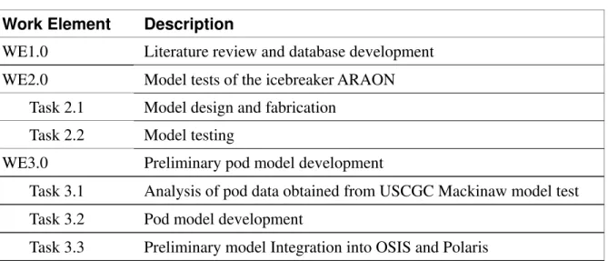
Table 1. Summary of Phase 1 work activities Work Element Description
WE1.0 Literature review and database development WE2.0 Model tests of the icebreaker ARAON
Task 2.1 Model design and fabrication Task 2.2 Model testing
WE3.0 Preliminary pod model development
Task 3.1 Analysis of pod data obtained from USCGC Mackinaw model test Task 3.2 Pod model development
Task 3.3 Preliminary model Integration into OSIS and Polaris
3 PHASE 1 COMPLETED TASKS AND RESULTS
The following subsections detail the tasks completed in Phase 1 (Fiscal Year 2009-2010) and highlight the key results.
3.1 Work Element 1: Literature Review and Database Development
To assist in model development, a comprehensive database was constructed of publicly available full- and model-scale ice manoeuvring test data. The database
facilitated the validation of the numerical models developed in this project by greatly improving access to the required experimental data. This effort results in the current version of the “Ship Manoeuvring Performance in Ice Database v1.0”.
A brief literature review on state-of-the-art of ship manoeuvring in ice was performed with focus given to current designs and practices. The influence of various ship design parameters on manoeuvring performance was identified. Over 120 reports and papers were reviewed and test data were extracted to populate a new database containing full- and model-scale ice manoeuvring test data. Post-1995 test data was taken directly from published reports; pre-1995 test data was taken from an existing database “Ship in Ice Performance Database Version 1.0” (TDC, 1995) available at the Transportation Development Centre of Transport Canada. The database was documented in Lau (2010a), which details the data contained in the new database and provides example analyses. The database has been created in spreadsheet form (Microsoft Excel) because this format facilitates basic analysis and the information can be easily converted to another format if required. The database is attached to the report as Appendix A.
Much care was taken to ensure accurate data reproduction during the creation of this database, however it is recommended that the data from “Ship in Ice
Performance Database Version 1.0” be verified, understanding that it may not be
possible to identify all the sources.
Maintenance of this database on a regular interval is also recommended by adding additional test data, when they become available.
3.2 Work Element 2: Model Tests of the Icebreaker ARAON
The majority of the resources in Phase 1 were devoted to model testing. This work includes fabrication of the ARAON model with additional funding from the Maritime and Ocean Engineering Research Institute (MOERI), part of the Korean Ocean Research and Development Institute (KORDI).
Task 2.1: Model design and fabrication
The ARAON is the new Korean icebreaker built and delivered by Hanjin Heavy Industry at the end of 2009 to its owner, KORDI. Under the auspices of KORDI, MOERI is collaborating with IOT to assess the performance of ARAON in ice, which complements this project. MOERI agreed to loan the ARAON model for this test on the manoeuvring performance of pod-drive ships in ice.
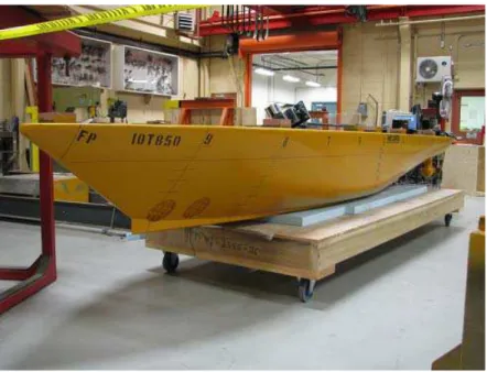
The ARAON is a 6,950-ton icebreaker designed for operation in 1-m thick multi-year ice conditions with continuous ice breaking capability at 3 knots. It is equipped with twin azimuth propulsion units driven by a diesel-electric propulsion plant. The model, shown in Figure 1, was constructed to a scale of 1:20. Similar to the ship, the model hull is fitted with an ice knife and bow thruster tunnels. It is finished and marked to IOT (ITTC) standards.
Figure 1. Bow view of the model ARAON (IOT Model 850)
To keep the cost to an acceptable level, IOT is providing free use of its current model pod propellers for these tests. The ARAON model is fitted with twin
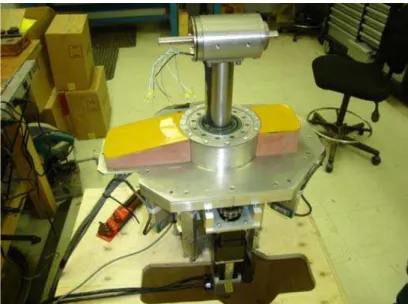
propellers, although it was agreed that exact duplication of the pod geometry is not necessary. Nevertheless, the shells of the pods were designed and fabricated as closely as feasible to the ARAON pod geometry provided by MOERI. The next three figures show the pods installed on the model, the inner structure of the pod and its global load measuring assembly.
Figure 3. The inner structure of the model pod
Figure 4. The global load measuring assembly
The design and fabrication of the ARAON model is documented in Lau (2010b). Task 2.2: Model testing
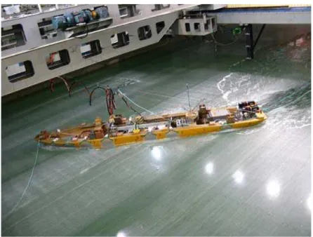
Free running tests of the scale model ARAON were conducted in a series of propulsion and manoeuvring runs in open water, level ice and pack ice. The main focus of these tests was the performance of the podded propulsors and their influence on ice-hull load distribution during ship manoeuvres. The manoeuvres included straight, zigzagging, and circular runs with control over propeller shaft speed and pod deflection angle. Figure 5 shows a typical turning circle run.
Figure 5. Turning circle run in level ice
Throughout testing, the model position, pod performance characteristics and ice-hull pressures were monitored. A relationship between propeller speed, pod angle setting and model motion was determined. Level ice turning circles and zigzag channels were measured, and qualitative pressure distribution observations were made.
The results indicated significant ice-hull loading over the model bow and outside stern during turning circles; high loading was experienced at the bow during straight runs. Very low ice-hull loading was observed at the model stern during straight runs. Comparison between loading on inside and outside turning surfaces was limited, as few sensors were mounted on the inside turning surface of the model.
The results also show that greater turning radii result from increasing propeller speed or ice thickness and reducing the azimuth angle.
It is recommended that future testing consider additional sensors on the inside model hull surface, in situ sensor calibration, wireless instrumentation, and a model-braking method that is less disruptive to collected data.
The model test is documented in Lau and Akinturk (2010). 3.3 Work Element 3: Preliminary pod model development
The propulsion forces and moments due to pods can be simulated numerically based on an empirical model developed from model test data. Ship simulators such as the Polaris system used at the Centre for Marine Simulation (CMS) require such a model to simulate pod-driven ships. At the IOT, a semi-empirical pod model has been developed and incorporated into its in-house simulation software for ships
manoeuvring in ice, OSIS-IHI3, based on the experimental data of the USCGC4 Mackinaw (Akinturk and Lau, 2010). This model is also implemented in the CMS simulators.
This work element focuses on the development of a semi-empirical pod model that can be implemented in OSIS and Polaris. This includes the following sub-tasks: • Task 3.1: Analysis of pod data obtained from USCGC Mackinaw model test • Task 3.2: Pod model development
• Task 3.3: Model Integration to OSIS and Polaris
Task 3.1: Analysis of USCGC Mackinaw model test pod data
A semi-empirical model was developed based on the USCGC Mackinaw pod test data (Akinturk and Lau, 2010). This data set was used for preliminary development of the model since the ARAON data were not available at the time of model development and since further model validation is available for comprehensive resistance and manoeuvring data.
The propellers for the twin pods were tested in their typical operational configuration, i.e., the tractor mode, on a 1:15.62 scale model of the USCGS icebreaker Mackinaw (Akinturk and Lau, 2010). The model was towed straight ahead at various speeds while the azimuth angle of one of the twin pods steered in the range of 0 to 180 degrees.
Two conditions were simulated for the pods during the experiments: static tests, in which the azimuth angle of the one of the pods was fixed at a certain azimuth angle for the duration of a run; dynamic tests, in which one of the pods was continuously steered from 0 to 360 degrees azimuth.
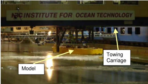
Figure 6 shows a typical test set up.
3
Ocean-Structure Interactions Simulator - Ice-Hull Interaction, © NRC
4
Figure 6. Experimental set-up of the USCGC Mackinaw model in the IOT ice tank
The thrust T and torque Q on the propeller shaft and the longitudinal force Fx and
transverse force Fy generated on the model ship hull by the pods were measured;
regressions on the test data convert these to non-dimensionalized coefficients, which are functions of advance coefficient J u
nD
= and steering angle δR. The thrust coefficient Kt is defined as follows:
Kt (J,δR)=T / 0.5 ρn2 D4 (1)
where ρ is the water density, n the propeller speed , and D the propeller diameter. The torque coefficient Kq is defined as follows:
(2)
2 5
( , ) / 0.5
q R
K J δ =Q ρn D
Finally, the non-dimensional force coefficients KFx and KFy are defined as:
and (3)
2 4
( , ) / 0.5
Fx R x
K J δ = −F ρn D KFy( ,J δR)= −Fy/ 0.5ρn D2 4
These coefficients are used in the subsequent model development. Task 3.2: Pod model development
The experiment is conducted in straight-ahead motion with the pod azimuth angle steered in a range from 0 to 180 degrees. Regression on test data was performed to describe the pod performance. The semi-empirical model is extended to cover a pod azimuth angle θ from 0 to 360o and advance coefficient J as well as accounting for the different wake effects during turning.
Towing Carriage Model
The test data are measured only in straight forward ship motion and the pod forces could be quite different at the same θ and J when the ship turns; therefore, the influences of hull-pod interaction, wake fraction, flow rectification coefficient and thrust deduction were investigated and incorporating into the model treatment.
These analyses result in a semi-empirical model that is capable of modeling pod performance for arbitrary ship manoeuvres. The model was further incorporated into IOT OSIS ship manoeuvring software for validation and to study the manoeuvring performance of the USCGC Mackinaw (Lau and Ni, 2010a).
The validation exercise was conducted by comparing the OSIS simulation results with those obtained from a CMS Polaris simulation under identical test conditions. The simulation at CMS is conducted using its existing pod model developed for the Mackinaw, while the OSIS simulation is run with the IOT pod model.
Since the propellers used in the IOT and CMS Mackinaw models are different, and thus generate different thrust at the same propeller speed, the validation is conducted at the same propeller power outputs, which corresponds to 130.5 rpm and 180 rpm for the IOT and CMS models, respectively.
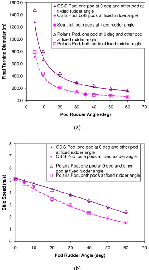
A range of rudder angles from 0 to 60o was imposed and the corresponding turning motion was simulated using OSIS and Polaris. The results are summarized in Figure 7 for turning diameter and advance speed. The turning diameter obtained from sea trials of the Mackinaw with rudders set to 35° is also given in Figure 7(a). Figure 7 shows good agreement among the OSIS simulation, Polaris simulation and limited sea trial data.
0.0 200.0 400.0 600.0 800.0 1000.0 1200.0 1400.0 1600.0 0 10 20 30 40 50 60 70
Pod Rudder Angle (deg)
Fi na l Tur n ing D ia m e te r ( m )
OSIS Pod, one pod at 0 deg and other pod at fixded rudder angle
OSIS Pod, both pods at fixed rudder angle Sea trial, both pods at fixed rudder angle Polaris Pod, one pod at 0 deg and other pod at fixed rudder angle
Polaris Pod, both pods at fixed rudder angle
(a) 0 1 2 3 4 5 6 7 8 0 10 20 30 40 50 60 70
Pod Rudder Angle (deg)
S h ip S p e e d ( m /s )
OSIS Pod, one pod at 0 deg and other pod at fixed rudder angle
OSIS Pod, both pods at fixed rudder angle Polaris Pod, one pod at 0 deg and other pod at fixed rudder angle
Polaris Pod, both pods at fixed rudder angle
(b)
Figure 7: Comparison of predictions from OSIS and Polaris simulations for turning in open water: (a) Turning diameter (b) Steady speed (OSIS with IOT Pod at 130.5 rpm and Polaris
Task 3.3: Model Integration to OSIS and Polaris
As part of this collaboration, the Marine Institute’s Centre for Marine Simulation5 (CMS) provides access to its Polaris simulation environment for mission rehearsal and training, including a unique capability to simulate operations in harsh environments. This IOT pod model enables improvement of CMS full mission bridge rehearsal of new operations and training for operations in harsh environments with pod-driven vessels.
This task was scheduled to start on Fiscal-Year 2010-2011; however, CMS is ready to provide access to its simulator for model implementation and validation ahead of schedule and their ship simulators, such as the Polaris system, are currently in need of an improved model to simulate pod-driven ships.
We have completed a preliminary implementation of the semi-empirical pod model and its on-site validation at CMS and the result is documented in Lau and Ni (2010b).
As the requirement of integration with Polaris, the IOT pod model was converted and re-formatted into a series of lookup tables useable by the Polaris software. The conversion procedure is presented in the report Lau and Ni (2010b).
A validation exercise was conducted by comparing the OSIS simulation results with those obtained from CMS Polaris simulation under identical test conditions.
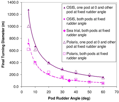
For this validation, we performed identical turning motion simulations of the Mackinaw using OSIS and Polaris, both with the IOT pod model. A range of rudder angles from 0 to 60o was imposed at a propeller speed of 180 rpm and the corresponding turning motion was simulated using OSIS and Polaris. The rudders were either steered by deflecting one pod to an angle with the other at zero degrees or deflecting both pods to the same angle. The results are summarized in Figure 8 for turning diameter and Figure 9 for advance speed. The turning diameter obtained from sea trials of the Mackinaw with both pods at 35 degrees is also given in Figure 8.
Figure 8 shows good agreement between the final turning diameter prediction and the sea trial data, which indicates that the pod model was correctly implemented in Polaris. Furthermore, the limited sea trial data agree well with simulation from both OSIS and Polaris. However, there are increasing discrepancies between the OSIS and Polaris results at smaller rudder angles, i.e., less than 5 degrees, with OSIS predicting higher turning diameters than Polaris.
0.0 200.0 400.0 600.0 800.0 1000.0 1200.0 1400.0 0 10 20 30 40 50 60 70
Pod Rudder Angle (deg)
Fi na l Tur n ing D ia m et e r ( m )
OSIS, one pod at 0 and other pod at fixed rudder angle OSIS, both pods at fixed rudder angle
Sea trial, both pods at fixed rudder angle
Polaris, one pod at 0 and other pod at fixed rudder angle Polaris, both pods at fixed rudder angle
Figure 8: Turning diameters simulated by Polaris and OSIS using IOT pod model
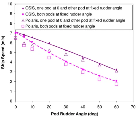
Figure 9 shows the ship speed generated by OSIS and Polaris for identical simulation conditions. Speed predictions for larger pod rudder angles agree well; however, again, there are increasing discrepancies between the OSIS and Polaris results at the smaller rudder angles, with OSIS predicting higher ship speeds. A possible source of this discrepancy was identified, but further validation is needed to verify that.
0 1 2 3 4 5 6 7 8 9 10 0 10 20 30 40 50 60 70
Pod Rudder Angle (deg)
Sh ip Sp e e d ( m /s )
OSIS, one pod at 0 and other pod at fixed rudder angle OSIS, both pods at fixed rudder angle
Polaris, one pod at 0 and other pod at fixed rudder angle Polaris, both pods at fixed rudder angle
Figure 9: Steady speed of turning motion simulated by Polaris and OSIS using IOT pod model
The reason for these discrepancies may be the different dynamic systems used by OSIS and Polaris to simulate ship manoeuvring and further model refinement is needed to improve the agreement.
4 LIST OF REPORTS AND PUBLICATIONS
The following is a summary list of publications generated for this project: Task 1.0: Literature review and database development
Lau, M., 2010a, Ship Manoeuvring Performance In Ice Database V1.0, NRC/IOT Report LM- 2010-07, Institute for Ocean Technology, National Research Council of Canada, St. John’s, Newfoundland and Labrador.
Task 2.0: Model tests of the icebreaker ARAON
Lau, M and Akinturk, A, 2010. Free Propulsion and Maneuvering Tests of Korean Icebreaker ARAON in Ice, IOT report LM-2010-10, Institute for Ocean Technology, National Research Council of Canada, St. John’s, Newfoundland and Labrador.
Task 3.1: Analysis of pod data obtained from USCGC Mackinaw model test
Akinturk, A and Lau, M, 2010. On The Performance of Podded Propulsors, IOT report LM-2010-05, Institute for Ocean Technology, National Research Council of Canada, St. John’s, Newfoundland and Labrador.
Task 3.2: Preliminary pod model development
Lau, M., and Ni, S.Y., 2010a, A Semi-Empirical Pod Model for USCG Icebreaker Mackinaw, NRC/IOT Report LM- 2010-06, Institute for Ocean Technology, National Research Council of Canada, St. John’s, Newfoundland and Labrador.
Tasks 3.3: Software integration to IOT OSIS and CMS Polaris and validation
Lau, M., and Ni, S.Y., 2010b, Free Propulsion and Maneuvering Tests of the Korean Icebreaker ARAON in Ice, NRC/IOT Report LM- 2010-08, Institute for Ocean Technology, National Research Council of Canada, St. John’s, Newfoundland and Labrador.
5 RECOMMENDATIONS FOR FUTURE WORK
We have completed the tasks as proposed for the first year, except the work on the pressure model is postponed to the second year. We have put together an extensive test database to assist in future model development and validation. An extensive model test was conducted using the Icebreaker ARAON model, in which valuable manoeuvring, propulsion and hull pressure data were collected. At the writing of this report, we have only been able to perform preliminary analysis of the data. Using the existing data on USCG Mackinaw model test, we have developed a semi-empirical pod model for ship manoeuvring simulation. We have completed a preliminary implementation of the model in both IOT OSIS and CMS Polaris simulation software and the resulting on-site validation was encouraging.
It is recommended that the data analysis of the ARAON model test be completed and to continue with the second phase of the project as per the original work plan. 6 REFERENCES
Transportation Development Centre, 1995, Ship/Ice Interaction Database Version 1.0 User’s Manual, Transportation Development Centre.
Lau, M., 2010a, Ship Manoeuvring Performance In Ice Database V1.0, NRC/IOT Report LM- 2010-07, Institute for Ocean Technology, National Research Council of Canada, St. John’s, Newfoundland and Labrador.
Lau, M., 2010b, ARAON Model Test Phase I: Model Design And Fabrication, NRC/IOT Report LM- 2010-04, Institute for Ocean Technology, National Research Council of Canada, St. John’s, Newfoundland and Labrador.
Lau, M and Akinturk, A, 2010. Free Propulsion and Maneuvering Tests of Korean Icebreaker ARAON in Ice, IOT report LM-2010-10, Institute for Ocean Technology, National Research Council of Canada, St. John’s, Newfoundland and Labrador.
Lau, M and Ni, S.Y., 2009. Ship Manoeuvring in Ice Simulation Software OSIS-IHI, IOT report LM-2009-02, Institute for Ocean Technology, National Research Council of Canada, St. John’s, Newfoundland.
Lau, M., and Ni, S.Y., 2010a, A Semi-Empirical Pod Model for USCG Icebreaker Mackinaw, NRC/IOT Report LM- 2010-06, Institute for Ocean Technology, National Research Council of Canada, St. John’s, Newfoundland and Labrador.
Lau, M., and Ni, S.Y., 2010b, Free Propulsion and Maneuvering Tests of the Korean Icebreaker ARAON in Ice, NRC/IOT Report LM- 2010-08, Institute for Ocean Technology, National Research Council of Canada, St. John’s, Newfoundland and Labrador.