HAL Id: hal-01010208
https://hal.archives-ouvertes.fr/hal-01010208
Submitted on 23 Sep 2014HAL is a multi-disciplinary open access archive for the deposit and dissemination of sci-entific research documents, whether they are pub-lished or not. The documents may come from teaching and research institutions in France or abroad, or from public or private research centers.
L’archive ouverte pluridisciplinaire HAL, est destinée au dépôt et à la diffusion de documents scientifiques de niveau recherche, publiés ou non, émanant des établissements d’enseignement et de recherche français ou étrangers, des laboratoires publics ou privés.
Removal of trimethylamine and isovaleric acid from gas
streams in a continuous flow surface discharge plasma
reactor
Aymen Amine Assadi, Abdelkrim Bouzaza, Marguerite Lemasle, Dominique
Wolbert
To cite this version:
Aymen Amine Assadi, Abdelkrim Bouzaza, Marguerite Lemasle, Dominique Wolbert. Removal of trimethylamine and isovaleric acid from gas streams in a continuous flow surface discharge plasma reactor. Chemical Engineering Research and Design, Elsevier, 2015, 93, pp.640-651. �10.1016/j.cherd.2014.04.026�. �hal-01010208�
1
Removal of trimethylamine and isovaleric acid from gas streams in a
1continuous flow surface discharge plasma reactor
23
Aymen Amine ASSADI a.b, Abdelkrim BOUZAZA a,b*,Marguerite LEMASLEa,b, Dominique WOLBERT a,b
4 a
Laboratoire Sciences Chimiques de Rennes - équipe Chimie et Ingénierie des Procédés, UMR 6226 5
CNRS, ENSCR, 11 allée de Beaulieu, 35700 Rennes, France. 6
b
Université Européenne de Bretagne. 7
* Corresponding author. Tel.: +33 2 23238056; fax: +33 2 23238120. 8
E-mail address: Abdelkrim.bouzaza@ensc-rennes.fr (A. Bouzaza) 9 10 11 Abstract 12 13
The removal of isovaleric acid (IVA) and trimethylamine (TMA) using nonthermal plasma 14
(NTP) in a continuous surface discharge reactoris investigated. The influence of the energy 15
density shows that its increment is accompanied by the increase of the removal rate. 16
Atflowrateequal to 2 m3.h-1, whenenergy densityextends three times, the removal rates of IVA 17
and TMAare increased from 5 to 15 mmol.m-2.h-1 and from 4 to 11 mmol.m-2.h-1,respectively. 18
The impact of relative humidity (RH) is also studied. An increase in % RH (up to 20%) leads 19
to a decrease of theremoval rate. Additionally, the formation of by-productsin thesurface 20
discharge reactorand the plausible reaction mechanism of the two VOC were alsodetected and 21
discussed.Moreover, a kinetic model taking into account the mass transfer step is developed in 22
order to represent the experimental results. The model shows a good agreement with 23 experimental results. 24 25 Keywords 26 27
Surface discharge, VOCs, mass transfer, relative humidity 28
29
1. Introduction 30
31
VOCs are hazardous to health and environment; their emission causes serious 32
environmental problems such as stratospheric ozone depletion, photochemical smog, 33
greenhouse effect and so on (US EPA, 2008;Le Cloirec, 1998). Increasing awareness of 34
these emissions has resulted in legislation requiring stringent enforcement of new regulations 35
to improve the quality of the environment (US EPA, 2008).To remove those gaseous 36
2 pollutants, many technologies have been developed but they are not very successful and do 37
not satisfy the strict social demands of the present ( Harling et al., 2008). One of the methods 38
which are developed for the control of VOCs is nonthermal plasma processing. This latest 39
process is a major area of research in both industry and academia (Le Cloirec, 1998; Harling 40
et al., 2008; Mista et al., 2008). 41
It is characterized by the formation of electrons, ions and neutral molecules. Energetic 42
electrons ionize and dissociate background molecules resulting in the formation of highly 43
reactive chemical species (radicals, ions, excited molecules and ozone) (Khani et al., 2011). 44
Literature has also shown that various types of electrical discharge have been investigated for 45
the oxidation of hydrocarbons: pulsed corona discharge(Ouni et al., 2009), atmospheric 46
pressure glow discharge(Yan et al., 2013), dielectric barrier discharge (DBD)(Mfopara et 47
al., 2009; Ye et al., 2013], packed-bed discharge(Jiang et al., 2013, Goujard et al., 2011; 48
Schmid et al., 2010) and surface discharge(Maciuca et al., 2012, Allegraud, 2007; Jolibois 49
et al., 2012). 50
Recently, many research attempts have been made to make up for the advantages of DBD 51
plasma reactors for particularly effective control of hazardous gas emissions and treating gas 52
streams with low VOC concentrations at low temperature[Ouni et al., 2009; Jolibois et al., 53
2012). In fact, DBD plasmareactorshavebeen widely studied in the area of hazardous and 54
toxic gases control, VOC abatement such as toluene (Mok et al., 2011; Huang et al., 20011; 55
Subrahmanyama et al., 2010) and dimetylamine(Ye et al., 2013), H2S and NH3 removal 56
(Ma et al., 2001), NOx removal from the flue gas (Jolibois et al., 2012; Yoshida, 2013). 57
The aim of our study is to improve understanding of the physical and chemical mechanisms 58
involved during nonthermal plasma (NTP) removal process of a typical VOC. In this work, 59
isovaleric acid and trimethylamine are chosen as representative of odorous compounds. These 60
compounds are the main molecules detected in the exhaust gases from animal quartering 61
centers (ADEME, 2005). 62
The focus is put on the study of kinetic removal of these pollutants and the effect of relative 63
humidity and some operating parameters.Moreover, in most cases, steady-state kinetic models 64
with plasma process in the literatureignore the effect of mass transfer (Mokt et al, 2001). That 65
could be presumed if turbulences in the system are high enough to consider the 66
surfacereaction as the limiting step in the apparent removal rate(Redolfi et al., 2009). Thus, 67
the influence of the mass transfer on the performance of NTP process will also be discussed. 68
3 2. Experimental 70 71 2.1. DBD plasma reactor 72 73
The used DBD plasmareactor is composed principally of a glass tube (58 mm id and 100 cm 74
length) (Fig. 1). To generate the DBDplasma, the reactor is covered by a copper grid forming 75
the outer electrode. The glass tube, 4 mm thickness, acts as the dielectric media. The inner 76
electrode is on aluminum. The applied high voltage is about 30 kV/40 mA and is a sine 77
waveform. The DBD plasma is obtained by submitting the electrodes to a sinusoidal high 78
voltage ranging from 0 to 30 kV at a 50 Hz frequency(Fig.1). The outer electrode is connected 79
to the ground through a 2.5 nFin order to collect the charges transferred through the 80
reactor(Manley, 1943). Theapplied voltage (Ua) and high capacitance voltage (Um) are 81
measured by LeCroy high voltage probes and recorded by a digital oscilloscope (Lecroy 82
Wave Surfer 24 Xs, 200 MHz) (Fig.1). 83
The design of this reactor (Fig.1) is the subject of a Patent Application BFF11L1041/MFH 84
(CIAT Patent, 2013). 85
The pollutants, isovaleric acid (IVA)andtrimethylamine (TMA), are injected continuously 86
using a syringe/syringe driver system (Kd Scientific Model 100) through a septum into the 87
gas stream. A heating system covering the injection zone sets the gas temperature and 88
facilitates the VOC vaporization ahead of the static mixer (Fig.2.a). The treated 89
flowratestream varies from 2 to 10 m3.h-1. 90 91 Fig.1 92 Fig.2.b 93 94 2.2. Product analysis 95 96
IVA analysisisperformed by FID-Gas chromatography (Fisons Chromatograph). A Chrompact 97
FFAP-CB column (25 m of length 0.32 mm of external diameter 0.32mm), which is specially 98
adapted for volatile fatty acids is used. Nitrogen gas constitutes the mobile phase. All injections 99
are performed manually with a syringe of 250 µl. 100
4 The TMAis analyzed by a gas chromatograph equipped with a nitrogen-phosphor detector 102
(NPD). The column is a capillary column VOLAMINE, its length is 60 m. The sample 103
injection is done with a syringe of 500 µl. 104
The experiments which are repeated two times; show a good reproducibility with 5% standard 105
deviation. This standard deviation is represents by vertical bars in the experimental results in all 106
figures. 107
An effort is also made to quantify the major reaction intermediates present in gas phase in 108
order to determine the main reaction routes and to better understand the mechanisms 109
involved. 110
The byproducts generated during the DBD plasma oxidation of IVA and TMAare identified 111
and evaluated by Gas Chromatograph-Mass spectrometer (GC-MS) (Perkin Elmer Clarus 112
500) equipped with an infrared (IR) detector.The temperature conditions in the oven, the 113
injection chamber and the detector are, respectively, 100, 120 and 200 °C. 114
Due to their low concentrations, byproducts are concentrated in a Carbotrap (25 ml) then 115
removed by thermal desorption unit coupled with GC-MS. 116
At the exit of the DBD plasmareactor a constant flowrate of 200 L/h is bubbled on iodine 117
solution. Standard iodometric titration method is used to estimate the downstream ozone 118
formation (Rakness et al., 1996). NOx and CO concentrations are measured by an NO/CO 119
ZRE gas analyzer. The CO2 concentrationis analyzedby a FourierTransform Infrared (FTIR) 120
spectrophotometer brand Environnement SA (Cosma Beryl reference 100). The measurement 121
accuracy is about 5%. 122
The removal rate (R) of IVA and TMA at any value of specific energy is calculated as: 123 .( in out) plasma Q R C C S (1) 124
WhereCin and Coutare the inlet and the outlet pollutant concentrations (mmol.m-3), 125
respectively; Q is the volumetric flowrate (m3.h-1) and Splasma the active surface of plasma 126
(m2). 127
Moreover we use the Lissajous plot method (Manley, 1943) for estimating mathematically 128
the power input (P) (fig. 2.b). P is obtained by multiplying the pulse frequency (Hz) and the 129
specific energy (SE) over a period (eq.3). 130
P (W) =SE (J) xfrequency (Hz) (2) 131
The energy density (ED) is then calculated as: 132
ED(J/L) = (3600x P(W) / Q(m3.h-1))/1000 (3) 133
5 The energy density (ED) value isvaried by changing the applied voltage (Ua).
134 135
Fig.2.b 136
137
The removal of isovaleric acid and trimethylamine in the DBD plasma reactor is evaluated at 138
several gas residence times, water vapor concentrations and influent pollutant concentrations 139
(Table 1). 140
Table 1 141
N.B.: The corresponding residence times in the annular plug-flow reactor for gas flowrates 142
equal to 2, 4 and 6 m3.h-1are respectively 1.2, 0.8 and 0.5 s. 143
The CO2 overall selectivity (CO overall selectivity can also be defined) may be a useful 144
parameter to assess the performance of the DBD plasma reactor towards VOC removal. It 145
allows an estimation the mineralization rate i.e. the ultimate reaction step, of the process. 146
The COxoverall selectivity is expressed as follow (eq. 4&5): 147
-
4 ' (%) 10 5 % out in x IVA x IVA x IVA in IVA CO CO CO s overall selectivity IVA conversion (4) 148
-
4 ' (%) 10 3 % out in x TMA x TMA x TMA in TMA CO CO CO s overall selectivity TMA conversion (5) 149 150where x = 1 for CO and x = 2 for CO2. [COx]IVA, [COx]TMA are respectively obtained after the 151
removal of IVA and TMA. [IVA]in and [TMA]in are respectively the inlet concentration of 152
IVA and TMA. 153
The coefficients 5 and 3 are the stoechiometric coefficients of the removal reaction. 154
The carbon balance (CB) is defined as the ratio (expressed in percentage) of the number of 155
moles of carbon present in the reaction products relative to their respective moles in each 156
pollutant removed. 157
CB values of IVA and TMA are expressed as: 158
CB(%) 100% 5 % x in IVA IVA CO other byproducts IVA IRE
(6) 159
CB(%) 100% 3 % x in TMA TMA CO other byproducts TMA IRE
(7) 160 1616 3. Results and Discussion
162 163
3.1.Flowrate and energy density 164
165
3.1.1. The removal rate 166
167
The removal rate of each VOC is studied by varying the energy density and flowrate (Fig.3a 168 and 3.b). 169 170 Fig. 3.a 171 Fig. 3.b 172
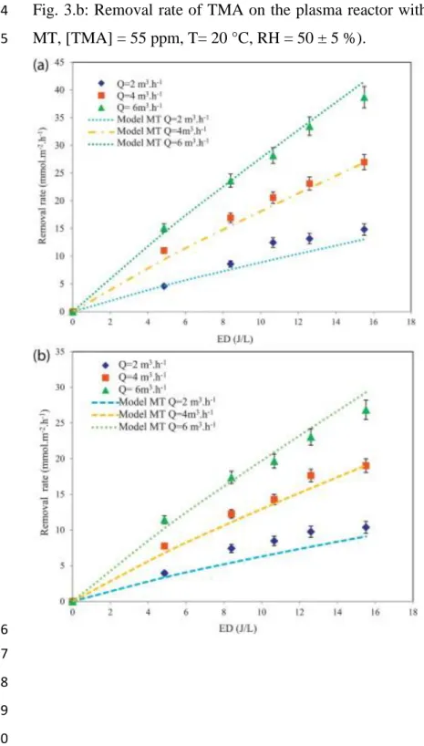
In the first instance, the effect of ED shows thatwhen this parameter increases the removal 173
rates of IVA and TMA increase also(Fig.3.a & b). In fact, at flowrate equal to 2 m3/h, when 174
EDextends three times, the removal rates of IVA and TMA are increased from 5 to 15 175
mmol.m-2.h-1 and from 4 to 11 mmol.m-2.h-1, respectively. This result is similar to those 176
reported for trichloromethane (Schmidt-Szałowski et al., 2011) acetylene (Redolfi et al., 177
2009) and toluene (Vandenbroucke et al., 2011), 178
This behavior was expected, as increasing the electric voltage across the reactor leads to 179
higher degree of ionization and higher reactive species production (Thevenetet al., 2008; 180
Wang et al., 2009). Therefore the pollutant has more probability to be attacked by electrons 181
or radicals, resulting in enhancing removal rates of IVA and TMA. Similar results have been 182
reported in the literaturefor some VOCs (Fridman, 2008;Vandenbrouckeet al., 2011). 183
By comparing the removal rate of each VOC, Fig. 3.a & b show that IVA is easier to be 184
removed. In fact, at an ED of 17 J/Land flowrate of 6 m3.h-1,the removal rate of IVA can 185
reach 39 mmol.m-2.h-1 where the removal rate of TMA is equal to 27 mmol.m-2.h-1. 186
The chemical bond strength and molecule stability are the main factors that can affect the 187
removal rate of VOCs in the NTP process(Schmidt-Szałowski et al., 2011;Wang et al., 188
2009;Assadi, 2012). 189
We note that, at a low value of ED, the effect of the flowrate is not important. This effect can 190
be explained that, at these conditions, low electrons and reactive species (such as •O and •OH) 191
are formed. Thus, the removal rate is probably limited by the chemical step. 192
A similar trend is observed for the two studied VOCs. 193
7 Thus, at high values of ED, the flowrate has more influence on the removal rate. The mass 194
transfer becomes the limited step. This is due to that, in laminar regime, the flowrate 195
increaseinvolves higher values of the Reynolds number (Re) from 368 to 1103 and mass
196
transfer coefficient (km) (Assadi et al.,2012). 197
198
3.1.2. The overall selectivities of CO and CO2 199
200
The increase of ED leads to an increase of the overall selectivities (Fig 4.a&b). This is 201
due to the fact that more electrons and reactive species (such as •O and •OH) are formed when 202
the ED increases and then more pollutants molecules are oxidized into CO2 and CO(Guaitella 203
et al., 2008). In fact, with TMA, an increase inED from 9 to 17 J/L leads to CO and CO2 204
overall selectivity increase from 4 to 11 % and from 16 to 25 %, respectively. These results 205
are in agreement with works on removal of toluene with plasma(Guo et al., 2006; Huang et 206
al., 2011; Liang et al., 2009), isovaleraldehyde (Maciuca et al., 2012), acetylene (Thevenet 207
et al., 2008 ; Guaitella et al.,2008), acetone (Schmid et al., 2010), benzene (Jiang et al., 208
2013; Fan et al., 2009) and dimethylamine (Ye et al., 2013). 209 210 Fig. 4.a 211 Fig. 4.b 212 213
In other hand, the mineralization of TMA is better than that of IVA. This can be explained by 214
the fact that less TMA is converted to intermediate compared to isovaleric acid. Thus the 215
intermediates have more probability to be attacked by electrons and active species. 216
217
3.2. Relative humidity 218
219
Many works (Thevenet et al.,2008;Vandenbrouckeet al., 2011) reported that relative 220
humidity (RH) can considerably alter the performances of NTP. 221
Water plays a very important role in the reaction since it decomposes into •OH and •H free 222
radicals in the plasma system (Ogata et al., 2004; Atkinson et al., 2003): 223
- • •
-2
H O+e H+ OH+e (1) 224
When RH is high, more H2O molecules collide with high energy electrons and •OH radicals 225
are formed. 226
8 Generally, VOCs can be removed by NTP via two pathways including (a) direct electron 227
attack and (b) indirect gas phase radical reactions (reactions between VOC molecules and 228
atomic oxygen •O or gas phase radicals such as •OH)(Ogata et al., 2002). On one side, water 229
molecules partially dissociate to form reactive species (Khani et al., 2011; Ouni et al., 230
2009;Vandenbrouckeet al., 2011). On the other side, water negatively influences VOC 231
removal due to its electronegative characteristics. Due to high water concentrations, increased 232
plasma attachment processes result in a reduced hydroxyl radical (•OH) production. It can be 233
concluded that two opposite phenomena are involved: water partially dissociates in the 234
plasma leading to reactive species, but humidity also negatively influences the plasma 235
characteristics. (Mista and Kacprzyk, 2008; Goujard et al., 2008;Capitelli, 1965). 236
So it will be interesting to study the influence of RH on the IVA and TMA removal. 237
238
3.2.1. The removal rate 239
240
The variation of removal rate of IVA and TMA with respect to RH is represented on Fig.5.a 241
and 5.b. Tests are performed at 20%, 55-60% and 85–90% RH. 242 243 Fig. 5.a. 244 Fig. 5.b. 245 246
We note that increasing water in the stream leads to a decrease of TMA‘s removal rate 247
(Fig.5.b). 248
It is unlikely that •OH radicals produced from water dissociation are responsible for TMA 249
removal. As a result of decreased electron density with increasing RH, the removal rate of 250
TMA decreases. 251
As reported by Guaitella et al (Guaitella et al, 2008) and Thevenet et al (Thevenet et al, 252
2008), oxygen atomic plays an important role on VOC oxidation under dry plasma treatment. 253
The disappearance of this specie due to H2O electron scavenging could explain the decrease 254
of the removal rate of VOC with an increasing H2O amount. 255
On the contrary, the removal rate of IVA by NTP is slightly promoted by increasing ofRH 256
from 20% to 50–60% (Fig. 5.a). This is probably due to the enhanced production of •OH 257
radicals, since the C-O substituent in isovaleric acid molecule can be more easily oxidized by 258
radicals as compared to the N-C link. 259
9 Adding more water in inlet gas mixture (RH> 60 %) has a negative effect on the removal rate 260
of IVA due to its electronegative characteristics. At higher RH electron density is reduced and 261
some reactive species are then quenched(Ogata et al., 2004; Thevenet et al., 2008). 262
263
3.2.2. The overall selectivity of CO2 264
265
The water vapour seems to play an important role on byproducts formation. CO2 overall 266
selectivity increases when RH increases. This tendency is the same for the two pollutants 267
studied (Fig 6 a. & b). 268 269 Fig.6.a 270 Fig 6.b 271 272
When RH raises from 25 to 90 %, at ED equal to 16.5 J/L, CO2‘s overall selectivity of IVA 273
and TMA increases from 25 to 34 % and from 21% to 30%, respectively. 274
As described previously, the water vapor is essential to the formation of •OH and •O which 275
promotes the mineralization of byproducts (Thevenet et al., 2008; Futamura et al., 276
1997).Moreover, several authors (Thevenet et al., 2008; Ogata et al., 2004) report that CO 277
and CO2 would be related by equilibrium under plasma action. In fact, water would be 278
supposed to favor the oxidation of CO leading to CO2. In fact, the presence of OH radicals 279
shifts the equilibrium towards the formation of CO2. 280
281
3.2.3. On the ozone formation 282
283
Ozone is an inevitable byproduct in a NTP. Atomic oxygen O is generated by molecular 284
dissociation due to an impact with high energy electrons (reaction 2). 285
e- + O2→ e- + O + O (2) 286
Atomic oxygen is a strong oxidizer, but its stability is very limited. Due to fast recombination 287
processes, the lifetime is only few microseconds at atmospheric pressure (Aggadi, 288
2006;Atkinson et al., 2003). 289
Atomic oxygen reacts with molecular oxygen in three-body collisions, forming ozone by the 290 following reaction: 291 O + O2 +M → O3 +M (3) 292
10 where M can be either molecular oxygen or molecular nitrogen (Atkinson et al., 2003).
293
The effect of ED on ozone formation is presented in Fig. 7.a and b. Whatever the value of RH 294
and the used VOC, the ozone formation follows the same trend i.e. it increases with the ED. 295
This can be explained by the fact that more electrons and reactive species (such as O) are 296
formed and then atomic oxygen reacts with molecular oxygen in three-body collisions, 297
(reactions 2 & 3) leading to ozone production(Redolfi et al., 2009). 298
Moreover, the decrease in ozone formation is also observed when RH increases. The quantity 299
of the produced ozone is reduced two times when the RH increases from 25 to 90%. 300
In fact, the formation of ozone is inhibited due to a series of radical reactions leading to fast 301
ozone consumption (Atkinson et al., 2003). The presence of water molecules activates the 302
reaction giving OH and O2H radicals which react with ozone. 303
First, water acts as electron acceptor, following this pathway (Atkinson et al., 2003): 304
H2O + e-H+ OH(4) 305
Then ozone is decomposed by H and HO radicals(Atkinson et al., 2003; Braci et al., 306 2011): 307 O3 +OH O2 + O2H(5) 308 O3 + H O2 + OH(6) 309
Globally, the effect of RH on the ozone production is relatively important. 310 Fig.7.a 311 Fig.7.b 312 313
3.3. Gas phase reaction intermediates 314
315
Byproducts formation is an important factor to be taken into account when NTP process is 316
carried out. VOCs removal often leads to the formation of some byproducts (Thevenet et al., 317
2008; Vandenbrouckeet al., 2011). 318
Fig.4.a and 4.b show that CBof each pollutant is achieved. This means that the majority of 319
organic byproducts are released from theDBD plasma reactor. 320
The gas stream in the exit of DBD plasma reactor is analyzed in order to identify the formed 321
byproducts.This is done in order to understand the reaction mechanism. 322
323
3.3.1. Case ofIVA 324
11 An air stream of 2 m3.h-1containing 55 ppm of IVAis treated in DBD plasma reactor. Six 326
byproducts are identified (Fig.8.a): acetone (CH3COCH3), isobutyric acid (CH3CH2CH2 -327
COOH), methanol (CH3OH), acetic acid (CH3COOH), COand CO2. 328
329
Fig.8.a 330
331
A removal pathway is proposed from literature study and is checked through experimental 332
investigations (Assadi, 2012; Aggadi,2006). The oxidation scheme of IVA consists of the 333
simultaneous carboxylic function removal and new function carried on an ‗n−1‘ carbon 334
molecule. So a possible removal pathway in series, whichleads to a complete mineralization, 335 is proposed inFig. 8.b. 336 Fig.8.b 337 338
Standard plasma radical kinetics based on O and OH oxidation of the compounds fails to 339
explain this distribution of the byproducts. Therefore the decomposition of C5H10O2 in the 340
discharge must proceed through a fast cleavage of the C–C and C-O bonds. Several processes 341
can be implied in the removal mechanism: direct electronic impact and chemical reactions 342
with ions or nitrogen excited states (Huang et al., 2011; Atkinson et al., 2003). 343
344
3.3.2. Case of TMA 345
346
Byproducts due to TMAremovalare also analyzed. Thus (Dimethylamino) acetonitrile, N, N-347
Dimethyl formamide, Nitromethane, acetone, acetic acid, methanol and ethanol are identified 348
(Fig.8.a). 349
The removal mechanism of trimethylamine seems to be more complex than isovaleric acid. 350
Byproducts containing nitrogenwould be formed at different removal steps. 351
352
Fig. 9.a 353
354
Moreover the oxidation of the trimethylamine leads to the formation of NOx. The amounts of 355
these byproducts are represented in Fig.9.b 356
357
Fig.9.b 358
12 359
Therefore, in our opinion, the possible removal pathway is that (Dimethylamino) 360
acetonitrile, N, N-Dimethyl formamide, Nitromethaneat atmospheric pressure are essentially 361
produced by the reactionof methyl radical with NO2(Braci et al., 2011, Harling et al., 2009, 362
Aggadi, 2006). 363
Moreover it is possible that after the main oxidation reactions another ―combination-364
reactions‖ can occurs between byproducts(Schmidt-Szałowski et al., 2011; Yoshida, 2013). 365
Maybe acetone and acetic acid are essentially due to TMA ―fragments‖ oxidation by CO. 366
While methanol and ethanol formation is due to acetic acid oxidation. 367
368
3.4. Modelling of kinetics and influence of the mass transfer 369
370
3.4.1. Model without mass transfer (WMT) 371
372
During the oxidation process in DBD plasma reactor two main steps can be considered: the 373
mass transfer step and the chemical reaction step. Usually the mass transfer stepis neglected. 374
Many authors (Goujard et al., 2011; Mokt et al., 2001; Wang et al., 2009; Redolfi et al., 375
2009)work only in batch reactor where mass transfer does not impact the kinetics, due to a 376
perfectly mixed gas phase. 377
By applying a mass balance over the entire length of the reactor we obtain: 378 2 0 2 ( b) b e d C dC D u R dz d z (8) 379
where De is the axial dispersion coefficient, Cb is the concentration of VOC on the gas phase, 380
u0 is the linear velocity in the reactor, z is any position along the reactor longitudinal axis and 381
R is the removal rate. 382
Moroever, here, the reactor has been confirmed as a plug-flow reactor (Assadi et al., 2012). 383
In fact, a residence time distribution (RTD) experiment was carried out using carbon dioxide 384
as a tracer substance. This lastwas injected during a very short time interval into the reactor 385
(Dirac function). The outlet carbon dioxide concentration is measured at the exit of reactor. 386
The tanks in series model were used to describe the response of the system. The experiments 387
of RTD revealed that our annular reactor could be assimilated to a cascade of 22 elementary 388
continuously stirred tank reactors. It is generally accepted that above a number of 20 389
elementary reactors, the experimental reactor can be considered as a plug flow 390
reactor(Vincent et al., 2008). Thus, the continuous pollutant removal along the radial 391
13 direction should not be ignored (Assadi, 2012; Guaitella et al., 2008). On the other side, the 392
axial dispersion can be neglected and the equation (9) can be expressed as: 393 0 d dC u R dz (9) 394
Moreover, many authors use the relation (10) to identify the removal rate of toluene and 395
acetone (Schmid et al.,2010;Chang et al., 2005), nitric oxide (Mokt et al., 396
2001),cyclohexane(Harling et al., 2009)and isovaleraldehyde (Maciuca et al., 2012)on the 397
DBD plasma reactors.This removal rate can be written as: 398 . inj inj d d d d d d reactor reactor E E P R k C k C Q k C V V (10) 399
where kd is the apparent rate constant, Cb and Cd are concentrations of VOC on the bulk and 400
discharge phases respectively, Vreactor is the reactor volume and P is the discharge power, τ is 401
the residence time of the pollutant on the DBD plasma reactor and Q is the flowrate. 402
Experimentally, the plot of Ln (Cin/Cout) vs. Einjwill allow determining the constant of 403
modelWMT.The values of the apparent rate constants (kd)are represented on table 2. We note 404
that the model WMT represents the experimental results with a good approach. However the 405
apparent constants of this model are flowrate dependent. Thus, we can conclude that the mass 406
transfer step cannot be neglected in this present study. Therefore the model that will be 407
developed below will reflect the influence of the transfer step. 408
409
Table 2 410
411
3.4.2. Model with mass transfer (MT) 412
413
In air,under atmospheric pressure, the electrical discharge is considered as filamentary. Each 414
time the discharge takes place, electrons and active species such as ions, radicals and excited 415
species are generated at the surface of glass tube. They recombine rapidly into more stable 416
species and can further diffuse in the bulk phase (Allegraud et al, 2007; Capitelli et al., 417
2000). The short life duration of radicals such as atomic oxygen •O makes that, in the bulk 418
phase, only the ozone is present(Allegraud et al., 2007;Vandenbrouckeet al., 2011). 419
Thus, the plasma process is broken down into two phases: 420
Transfer of gaseous reagents from gas phase to the discharge phase 421
Oxidation reaction between gaseous reagents on the discharge phase. 422
By applying a mass balance over the two phases of the reactor we obtain: 423
14 Gas phase: 0 b dC u T dz (11) 424 Discharge phase: d d P T k C V (12) 425
Where T is the mass transfer between the two phases. It can be estimated as(Bouzaza et al., 426 2006): 427
m v b d T k a C C (13) 428where km is the mass transfer coefficient (m.s-1) and av is the area of discharge per unit 429
volume of the reactor (m2.m-3).avis kept constant and is equal to 134 m2.m-3 . 430
The external mass-transfer coefficient, km is estimated using a correlation developed for 431
laminar flow in annular reactors(Mobarak et al.,1997): 432 -0,472 0,33 0.55 1, 029 Re Ltot Sh Sc d (14) 433
where L tot is the length of the annular reactor, d is its equivalent diameter, and Sh, Sc and Re 434
are respectively Sherwood, Schmidt and Reynolds dimensionless numbers. 435
The values of Re and km are given in table 3. 436
437
Table 3 438
439
By combining equations (11) and (12), an algebraic resolution from z = 0 to z = L and C from 440 Cin to Cout, gives: 441 0 0 1 ( ) .exp . 1 . . 1 . b m v d inj m v k a C z L C L k E u k a (15) 442 443
The constant kd of each pollutant is determined by numeric resolution using solver Excel. For 444
each experimental point, a target cell is defined as the difference between the experimental 445
and the theoretical removal rate. 446
The value of the apparent rate constant kd obtained is summarized in Table 4. 447
448
Table 4 449
15 Fig. 3.a and 3.b show that the model is adequate to correlate the experimental results. 450
According to the literature, these results are in agreement with those reported for some VOCs 451
(Subrahmanyama et al., 2010,Wang et al., 2009; Redolfi et al., 2009). 452
In addition, it is interesting to note that this constant is not flowrate dependent. The influence 453
of this last parameter is integrated on the expression of km. In fact, the separation between the 454
mass transfer and the chemical reaction steps is obtained. 455
456
4. Conclusions 457
458
We have unambiguously shown that the removal rate of IVA and TMA can be improved by 459
increasing the energy density. The increase of flowrate leads to a better removal rate of tested 460
VOCs. 461
On the other hand, at higher levels of RH, an inverted trend occurs and the removal of the two 462
VOCs becomes slightly lower. Intermediates byproductsare also identified. Thus, removal 463
pathways of the pollutants are also proposed. 464
Moreover, a model based on chemical and mass transfer steps is developed to represent the 465
experimental results. The influence of mass transfer is estimated by using semi-empirical 466
model. Thus an apparent rate (kd) and mass transfer (km) constants are determined 467
independently. 468
This model describes successfully the removal of IVA and TMA by DBD plasma. 469
470
Acknowledgment 471
472
The authors gratefully acknowledge the financial support provided by the French National 473
Research Agency (ANR) for this research work. 474 475 476 477 478 479 480 481 482
16 483
References 484
485
ADEME, 2005. Pollutions olfactives : origine, législation, analyse, traitement, Ademe, 486
Dunod, Angers. 487
488
Allegraud K., 2008. Décharge à barrière diélectrique de surface : physique et procédé, thèse 489
Ecole polytechnique de Paris. 490
491
Aggadi N.,2006. Étude de la réactivité de suies modèles de n-hexane sous décharge couronne 492
pulsée à la pression atmosphérique, Université de Paris Nord-France 493
494
Assadi A.A., 2012. Développement d‘un procédé de couplage réacteur plasma DBD-réacteur 495
photocatalytique pour le traitement des effluents gazeux : du laboratoire à l'application 496
industrielle, Thèse n ° 009. Rennes: ENSC Rennes. 497
498
Atkinson R., Baulch D. L., Cox R. A., Crowley J. N., Hampson R. F., Hynes R. G., Jenkin M. 499
E., Rossi M. J., Troe J., 2003. Evaluated kinetic and photochemical data for atmospheric 500
chemistry: Part 1 - gas phase reactions of Ox, HOx, NOx and SOx species Atmospheric 501
chemistry and Physics Discussions, 3, 6179–6699. 502
503
Bouzaza, A., Vallet, C., Laplanche, A., 2006. Photocatalyticremoval of some VOCs in the gas 504
phase using an annular flow reactor determination of the contribution of mass transfer and 505
chemical reaction steps in the photodegradation process. J. Photochem. Photobiol. A: Chem. 506
177, 212–217. 507
508
Braci L., Ognier S., Liu Y.N., Cavadias S., 2011. Post-discharge treatment of air effluents 509
polluted by butyl-mercaptan: role of nitrate radical, Conference Series 275, 12-13. 510
511
Capitelli M., Ferreira C.-M., Gordiets B., Osipov A., 2000. Plasma kinetics in atmospheric 512
gases, C.-M. Ferreira, B. Gordiets, A. Osipov (Eds.), in: Springer Series on Atomic, Optical, 513
and Plasma Physics, Eds 31, Springer-Verlag, Berlin. 514
17 Capitelli M., 1965. Plasma Kinetics in Atmospheric Gases, New York -Springer.
516 517 518
Chang Ch.-L., Lin T.-Sh., 2005. Decomposition of Toluene and Acetone in Packed Dielectric 519
Barrier discharge Reactor, Plasma Chemistry and Plasma Processing, 25, 227-243. 520
521
Derakhshesh M., Abedi J., Hassanzadeh H., 2010, Mechanism of methanol decomposition by 522
non-thermal plasma, Journal of Electrostatics 68, 424-428. 523
524
Fan H.Y., Shi C. , Li X.S. , Zhao D. Z., Xu Y. , Zhu A.M., 2009. High-efficiency plasma 525
catalytic removal of dilute benzene from air, Journal of Physics D—Applied Physics 42 526
225105- 225110. 527
528
Fridman A. 2008. Plasma chemistry. New York: Cambridge University Press. 529
530
Futamura S., Zhang A. H., Yamamoto T., 1997. the dependence of non thermal plasma 531
behavior of VOCs on their chemical structures Jwournal of Electrostatics 42, 51-62. 532
533
Goujard V., Tatibouet J-M., Batiot-Dupeyra C., 2011. Carbon Dioxide Reforming of Methane 534
Using a Dielectric Barrier Discharge Reactor: Effect of Helium Dilution and Kinetic Mode, 535
Plasma Chem Plasma Process 31, 315–325. 536
537
Guaitella O., Thevenet F., Puzenat E., Guillard C., Rousseau A., 2008. C2H2 oxidation by 538
plasma/TiO2 combination: Influence of the porosity, and photocatalytic mechanisms under 539
plasma exposure, Applied Catalysis B: Environmental, 80, 296–305. 540
541
Guo Y. F., Ye D.-Q., Chen K.-F, Tian Y.F., 2006. Humidity Effect on Toluene 542
Decomposition in aWire-plate Dielectric Barrier Discharge Reactor, Plasma Chem Plasma 543
Process 26, 237–249. 544
545
Harling A. M., Glover D. J., Whitehead J. C., Zhang, K., 2008. Industrial Scale Destruction of 546
Environmental Pollutants using a Novel Plasma Reactor, Ind. Eng. Chem. Res. 47, 5856–586. 547
18 Jolibois J., Takashima K., Mizuno A., 2012. Application of a non-thermal surface plasma 549
discharge in wet condition for gas exhaust treatment: NOx removal, Journal of Electrostatics, 550
70, 300-308. 551
552
Harling A.M., Glover D. J., Whitehead J. Ch., Zhang K., 2009. The role of ozone in the 553
plasma-catalytic destruction of environmental pollutants, Applied Catalysis B: Environmental 554
90, 157–161. 555
556
Huang H., Ye D., Leung D. Y. C., 2011. Abatement of Toluene in the Plasma-Driven 557
Catalysis: Mechanism and Reaction Kinetics, IEEE transactions on plasma science, 39, 877-558
882. 559
560
Jiang N., Lu N., Shang K., Li J., Wu Y., 2013. Effects of electrode geometry on the 561
performance of dielectric barrier/packed-bed discharge plasmas in benzene degradation. 562
Journal of Hazardous Materials 262, 387–393 563
564
Jiwu L., Lei F., 2013. Modeling of corona discharge combined with Mn2+ catalysis for the 565
removal of SO2 from simulated flue gas, Chemosphere 91, 1374–1379 566
567
Khani M.R., RazaviBarzoki S.H., SahbaYaghmaee M., Hosseini S.I., Shariat M., Shokri B., 568
Fakhari A.R., Nojavan S., Tabani H., Ghaedian M., 2011. Investigation of cracking by 569
cylindrical dielectric barrier discharge reactor on the n-hexadecane as a model compound, 570
IEEE Trans. Plasma Sci. 39, 1807–1813. 571
572
Le Cloirec P., 1998. Les composés organiques volatils dans l‘environnement, Lavoisier, Paris 573
574
Liang W., Li J., Li J., Jin Y., 2009. Abatement of toluene from gas streams via ferro-electric 575
packed bed dielectric barrier discharge plasma, Journal of Hazardous Materials 170, 633–638. 576
577
Maciuca A., Batiot-Dupeyrat C., Tatibouet J-M., 2012. Synergetic effect by coupling 578
photocatalysis with plasma for low VOCs concentration removal from airApplied Catalysis B: 579
Environmental, 125, 432-438. 580
19 Ma H., Chen P., Ruan R., 2001. H2S and NH3 Removal by Silent Discharge Plasma and 582
Ozone Combo-System, Plasma Chemistry and Plasma Processing 21, 611-624. 583
584
ManleyT.C., 1943. Transactions of the electrochemical society,. Proceedings of the 84th 585
General Meeting, New York 84, p. 83. 586
587
Mfopara A., Kirkpatrick M. J., Odic E., 2009. Dilute methane treatment by atmospheric 588
pressure dielectric barrier discharge: effects of water vapor, Plasma Chemistry and Plasma 589
Processing 29, 91–102. 590
591
Mista W., Kacprzyk R., 2008. Decomposition of toluene using non-thermal plasma reactor at 592
room temperature, Catalysis Today 137, 345–349. 593
594
Mobarak A. A., Farag H. A., Sedahmed G.H., 1997. Mass transfer in smooth and rough 595
annular ducts under developing flow conditions Journal of applied electrochemistry. 27, 201-596
207. 597
598
Mok Y. S., Lee Ho W., Hyun Y. J., Ham S. W., Nam I. S., 2001. Determination of 599
Decomposition Rate Constants of Volatile Organic Compounds and Nitric Oxide in a 600
Pulsed Corona Discharge Reactor, Korean J. Chem. Eng, 18, 711-718. 601
602
Mok Y.S., Kim D.H., 2011. Treatment of toluene by using adsorption and nonthermal plasma 603
oxidation process Current applied physics, 11,S58–S62. 604
605
Ogata A., Ito D., Mizuno K., Kushiyama S., Gal A., Yamamoto T., 2002. Effect of coexisting 606
components on aromatic decomposition in a packed-bed plasma reactor,Applied Catalysis A: 607
General, 236, 9–15. 608
609
Ogata A., Ito D., Mizuno K., Kushiyama S., Gal A., Yamamoto T., 2004. Effect of coexisting 610
components on aromatic decomposition in a packed-bed plasma reactor, Radiation Physics 611
and Chemistry 69, 281–287. 612
20 Ouni F., Khacef A., Cormier J. M., 2009. Gas Production from Propane Using Atmospheric 614
Non-thermal Plasma PlasmaChem Plasma Process, 29, 119–130. 615
616
Petit P., Vialle P.-J., Maciuca A., Batiot-Dupeyrat C., Tatibouet J.-M., Assadi A., Bouzaza A., 617
Wolbert D., Vallet C., 2013. Dispositif, système et procédé de traitement de gaz. CIAT, 618
ENSCR, CNRS. France. N°1350906. 619
620
Rakness K., GordonG., LanglaisB., MasscheleinW. , Matsumoto N., RichardY., Robson C. 621
M. , Somiy I. ,1996. Guideline for Measurement of Ozone Concentration in the Process Gas 622
From an Ozone Generator, 18, 209-229. 623
624
Redolfi M., Aggadi N., Duten X., Touchard S., Pasquiers S., Hassouni K., 2009. Oxidation of 625
Acetylene in Atmospheric Pressure Pulsed Corona Discharge Cell Working in the 626
Nanosecond Regime, Plasma Chem Plasma Process 29,173–195. 627
628
Schmidt-Szałowski K., Krawczyk K., Sentek J., Ulejczyk B., Górska A., Młotek M., 2011, 629
Hybrid plasma-catalytic systems for converting substances of high stability, greenhouse gases 630
and VOC. chemical engineering research and design 89, 2643–2651 631
632
Schmid S., Jecklin M.C., Zenobi R., 2010. Degradation of volatile organic compounds in a 633
non-thermal plasma air purifier, Chemosphere, 79, 124–130. 634
635
Subrahmanyama Ch., Renken A., Kiwi-Minsker L., 2010. Catalytic non-thermal plasma 636
reactor for abatement of toluene, Chemical Engineering Journal 160, 677–682. 637
638
Subrahmanyam Ch., Magureanu M., Kiwi-Minsker L., Renken A., 2006. Catalytic abatement 639
of volatile organic compounds assisted by non-thermal plasma: part II. Optimized catalytic 640
electrode and operating conditions. ApplCatal B, 65, 157-162. 641
642
Thevenet F., Guaitella O., Puzenat E., Guillard C., Rousseau A., 2008. Influence of water 643
vapour on plasma/photocatalytic oxidation efficiency of acetylene, Applied Catalysis B: 644
Environmental, 84, 813–820. 645
21 US EPA, 2008. Clean Air Act. US Code. Environmental Protection Agency. Washington, DC. 647
648
Vandenbroucke A. M., Morent R., De Geyter N., Leys Ch., 2011. Non-thermal plasmas for 649
non-catalytic and catalytic VOC abatement, Journal of Hazardous Materials 195, 30–54. 650
651
Vincent G., Marquaire P.M., Zahraa O., 2008. Abatement of volatile organic compounds 652
using an annular photocatalytic reactor: study of gaseous acetone, J.Photochem. Photobiol. A: 653
Chem. 197, 177–189. 654
655
Wang H., Li D., Wu Y., Li J., Guofeng L., 2009. Removal of four kinds of volatile organic 656
compounds mixture in air using silent discharge reactor driven by bipolar pulsed power, 657
Journal of Electrostatics 67, 547–555. 658
659
Yang H., An B., Wang Sh., Li L., Jin W., Li L., 2013. Destruction of 4-phenolsulfonic acid in 660
water by anodic contact glow discharge electrolysis, Journal of Environmental Sciences, 25(6) 661
1063–1070 662
663
YeZh., Zhao J., Huang H. y., Ma F., Zhang R., 2013. Decomposition of dimethylamine gas 664
with dielectric barrier discharge, Journal of Hazardous Materials 260, 32–39 665
666
Yoshida K., 2013, Diesel NOx aftertreatment by combined process using temperature swing 667
adsorption, nonthermal plasma, and NOx recirculation: NOx removal accelerated by 668
conversion of NO to NO2, Journal of the Taiwan Institute of Chemical Engineers, 44,1054– 669 1059. 670 671 672 673 674 675 676 677 678 679 680
22 681 682 Table captions 683 684
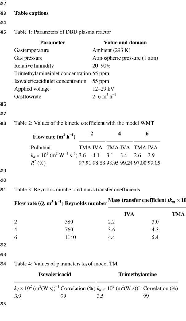
Table 1: Parameters of DBD plasma reactor 685
Parameter Value and domain Gastemperature Ambient (293 K)
Gas pressure Atmospheric pressure (1 atm) Relative humidity 20–90% Trimethylamineinlet concentration 55 ppm Isovalericacidinlet concentration 55 ppm Applied voltage 12–29 kV Gasflowrate 2–6 m3 h−1 686 687
Table 2: Values of the kinetic coefficient with the model WMT 688
Flow rate (m3 h−1) 2 4 6
Pollutant TMA IVA TMA IVA TMA IVA
kd × 102 (m2 W−1 s−1) 3.6 4.1 3.1 3.4 2.6 2.9
R2 (%) 97.91 98.68 98.95 99.24 97.00 99.05 689
690
Table 3: Reynolds number and mass transfer coefficients 691
Flow rate (Q, m3 h−1) Reynolds number Mass transfer coefficient (km × 10 3 , m s−1) IVA TMA 2 380 2.2 3.0 4 760 3.6 4.3 6 1140 4.4 5.4 692 693
Table 4: Values of parameters kd of model TM 694
Isovalericacid Trimethylamine
kd × 102 (m2(W s))−1 Correlation (%) kd × 102 (m2(W s))−1 Correlation (%)
3.9 99 3.5 99
23 696 697 Figure captions 698 699
Fig. 1: General electric schema of the DBD plasma reactor 700 701 702 703 704 705 706 707 708 709 710 711 712 713 714 715 716
24 717
718
Fig. 2.a: Experimental Set-Up 719
Fig. 2.b: Lissajous curve obtained at 50 Hz. 720
25 721
Fig. 3.a: Removal rate of IVA on the plasma reactor with the ED at different flowrate (Model: 722
MT, [IVA] = 55 ppm, T= 20 °C, RH = 50 ± 5 %). 723
26 Fig. 3.b: Removal rate of TMA on the plasma reactor with ED at different flowrate (Model: 724 MT, [TMA] = 55 ppm, T= 20 °C, RH = 50 ± 5 %). 725 726 727 728 729 730 731 732 733 734
Fig. 4.a: Variation of the CO‘s and CO2‘s selectivities (%) and balance of Carbon vs. ED - 735
Isovaleric acid (T= 20 °C, RH = 25%, Q=2 m3.h-1, [IVA] = 55 ppm). 736
27 Fig. 4.b: Variation of the CO‘s and CO2‘s selectivities (%) and balance of Carbon vs. ED - 737 Trimethylamine (T= 20 °C, RH = 25%, Q=2 m3.h-1, [TMA] = 55 ppm). 738 739 740 741 742 743 744 745 746
Fig.5.a.Variation of removal rate of IVA on the plasma reactor with relative humidity at 747
different ED ([IVA] = 55 ppm, T= 20 °C, Q= 2 m3.h-1). 748
28 Fig.5.b.Variation of removal rate of TMA on the plasma reactor with relative humidity at 749
different density energy ([TMA] = 55 ppm, T= 20 °C, Q= 2 m3.h-1) 750 751 752 753 754 755 756 757
Fig. 6a Variation of CO2 selectivity vs % RH at different values of ED([TMA] = 55 ppm, T= 758
20 °C, Q = 2 m3.h-1). 759
29 Fig 6.b Variation of CO2 selectivity vs % RH at different values of ED([IVA] = 55 ppm, T= 760 20 °C, Q = 2 m3.h-1). 761 762 763 764 765 766 767
Fig 7.a Variation of ozone production vs % RH at different values of ED ([TMA] = 55 ppm, 768
T= 20 °C, Q = 2 m3.h-1). 769
30 Fig 7.b.:Variation of the ozone production vs % RH at different values of ED ([IVA] = 55 770 ppm, T= 20 °C, Q = 2 m3.h-1). 771 772 773 774 775 776 777 778
Figure 8.a: GC-MS spectrum of IVA byproducts(ED = 13.4 J/L, [IVA] = 55 ppm, T= 20 °C, 779
Q = 2 m3.h-1). 780
Fig. 8.b: A possible pathway of isovaleric acid destruction on DBD plasma reactor. 781
31 782 783 784 785 786
Fig.9.a: GC-MS spectrumof TMA by-products (ED=13.4 J/L, [TMA] = 55 ppm, T= 20 °C, Q 787
= 2 m3.h-1). 788
Fig. 9.b: Variation of amount of NO and NOx vs ED(% RH= 50 %, [TMA] = 55 ppm, T= 20 789
°C, Q = 2 m3.h-1). 790
32 791


![Fig. 6a Variation of CO 2 selectivity vs % RH at different values of ED([TMA] = 55 ppm, T=](https://thumb-eu.123doks.com/thumbv2/123doknet/14403241.510340/29.892.85.570.123.950/fig-variation-selectivity-rh-different-values-ed-tma.webp)
![Fig 7.a Variation of ozone production vs % RH at different values of ED ([TMA] = 55 ppm, 768](https://thumb-eu.123doks.com/thumbv2/123doknet/14403241.510340/30.892.87.550.131.941/fig-variation-ozone-production-rh-different-values-tma.webp)
![Figure 8.a: GC-MS spectrum of IVA byproducts(ED = 13.4 J/L, [IVA] = 55 ppm, T= 20 °C, 779](https://thumb-eu.123doks.com/thumbv2/123doknet/14403241.510340/31.892.86.539.132.892/figure-gc-ms-spectrum-iva-byproducts-ed-iva.webp)
![Fig. 9.b: Variation of amount of NO and NO x vs ED(% RH= 50 %, [TMA] = 55 ppm, T= 20 789](https://thumb-eu.123doks.com/thumbv2/123doknet/14403241.510340/32.892.114.781.105.832/fig-variation-vs-ed-rh-tma-ppm-t.webp)
