HAL Id: hal-02131425
https://hal.archives-ouvertes.fr/hal-02131425
Submitted on 16 May 2019
HAL is a multi-disciplinary open access
archive for the deposit and dissemination of
sci-entific research documents, whether they are
pub-lished or not. The documents may come from
teaching and research institutions in France or
abroad, or from public or private research centers.
L’archive ouverte pluridisciplinaire HAL, est
destinée au dépôt et à la diffusion de documents
scientifiques de niveau recherche, publiés ou non,
émanant des établissements d’enseignement et de
recherche français ou étrangers, des laboratoires
publics ou privés.
Top-down Approach
Bruno Wacogne, Stéphanie Py, Audrey Guitton, Karine Charriere, Lionel
Pazart
To cite this version:
Bruno Wacogne, Stéphanie Py, Audrey Guitton, Karine Charriere, Lionel Pazart. Medical Devices
Development: the Bottom-up or the Top-down Approach. International Journal of Biosensors and
Bioelectronics (IJBSBE), 2017, 3 (5), pp.79. �hal-02131425�
Type of Article:
Opinion
Title:
Medical Devices Development: the Bottom-up or the Top-down
Approach?
Bruno Wacogne
1,2,*, Stéphanie Py
2, Audrey Guitton
1, Karine Charrière
2and Lionel Pazart
21 FEMTO-ST institute, Univ. Bourgogne Franche-Comté, CNRS, 15B avenue des Montboucons, 25030 Besançon,
cedex, France
2 INSERM CIC 1431, Besançon University Hospital, 2 place St Jacques, 25030 Besançon cedex, France
* Corresponding author: Bruno Wacogne, FEMTO-ST institute, Univ. Bourgogne Franche-Comté, CNRS, 15B avenue des Montboucons, 25030 Besançon, cedex, France.
Tel: + 33 3 81 66 63 88 Fax: + 33 3 81 66 64 23
Abstract:
Biomedical sensors are often developed under a bottom-up approach, i.e. the researcher point of view or laboratory approach. This is usually the case for microfluidic based integrated systems. The small number of such devices actually translated for use in clinical situations is mostly due to the need of sample pre-treatment by specially trained people and to the fact that industrial transfer had not been taken into account since the very beginning of the development. Conversely, the top-down approach places the end-user at the center of development discussion. In this end-user point of view approach, the participation of industrial, medical and end-users partners more often leads to the design of fully integrated and automated devices which, furthermore, can be manufactured using conventional industrial capabilities. In this opinion communication, we briefly summarize the most common biosensors technologies and we explain how immuno-combined devices may help addressing constraints related to their use in clinical situations in terms of usability by non-trained people, automation and integration.
Keywords: immuno-assay, medical device, bi-directional translational research. Abbreviations:
SPR: Surface plasmon resonance
ISFET: Ion sensitive field effect transistor EnFET: Enzyme field effect transistor µTAS: Micro total analysis system HCMV: Human cytomegalovirus
CNC: Computer numerical control CAD: Computer assisted design BSA: Bovine serum albumin HPAb: Human polyclonal antibody HRP: Horseradish peroxidase PBS: Phosphate saline buffer Introduction
Biosensors technologies have been the subject a several review papers. These reviews are either presented through the prism of the technology involved or through the prism of the application domains addressed. Technologically speaking, one can mention biosensors based on electrochemical methods [1], Surface Plasmon Resonance (SPR), fluorescence, electro or chemiluminescence [2]. Ion Sensitive Field Effect Transistors (ISFET) or Enzyme Field Effect Transistors (EnFET) are the subject of a large amount of publications and several ISFET/EnFET configurations are described [3-5]. Acoustic waves can also be used for sensing. Depending on the biosensor development, different acoustic wave regime can be employed [6]. The use of optics for biomedical applications is described in several reviews [7-9].
Generally, biosensors involve a sensing surface, or bio-receptor, which interacts with a biological sample containing targeted biological entities. Among bio-receptors employed in biosensors, antibodies and antigens based methods are probably the most popular. In these immuno-assays, either antigens are grafted onto the biosensor’s surface and targeted antibodies are captured or antibodies are used to capture antigens contained in the sample to be analyzed [10].
Typically two approaches are considered when fabricating biosensors. The first one directly derives from laboratory experiments. It generally consists in simplifying and integrating bulk experiments and to validate the resulting integrated device with artificial test samples or samples obtained from patients or volunteers in the frame of clinical trials. In section 2 of this opinion paper, we discuss this “researcher point of view” approach and assess the limits of such a strategy, especially in terms of usability in clinical situations. The second approach consists in only considering the laboratory results as a proof of concept and to re-invent a brand new medical device by placing the end-user at the center of the design strategy. In part 3, we comment on this “end-user point of view” strategy and describe how this approach increases the probability to design a device which can directly be used in clinical situations. This section will be shortly illustrated with results concerning blood transfusion safety and virus screening.
Researcher point of view: the bottom-up approach
Over the past decades, tremendous efforts have been put to the development of microfluidic technologies in order to propose integrated lab-on-chips or micro Total Analysis Systems (µTAS) [11]. Cleanroom facilities are put to profit to perfectly control the geometry of micrometer size channels and interaction chambers (area of the µTAS where the bio-interaction takes place). As explained in reference [11], the idea of using microfabrication techniques is to reduce the volume of the biological sample under analysis. Indeed, different microfluidic principles are described together with examples of applications involving immunoassays among others [12-14]. It is explained that the smallest sample volumes can be achieved using digital microfluidics.
Reducing the sample volume using microfabrication technologies illustrates the bottom-up approach where technological aspects are at the center of the development discussions. One major drawback of this approach is that, due to the reduced size of the microfluidic channels and interaction chambers, biological samples must be prepared in order to extract specific fluid/particles phases from the raw sample (for example: serum, platelets or red cells for blood analysis). This enhances the bio-recognition occurring at the bio-receptor’s surface because pre-treatment of the sample reduces the risk of non-specific interaction and also reduces the presence of unwanted large size particles which shield the bio-receptor. Although research is ongoing in the field of integrated sample preparation devices [15], human manipulation is still often required.
This is one of the main reasons which explains that only a few number of devices developed using the bottom-up approach leads to actual medical devices which can be used in clinical environment. Indeed,
members of staff must be specifically trained for each kind of sample preparation which mostly restrict the use of these integrated systems in biology laboratories environment. In clinical or point-of-care situations, sample preparation cannot be performed by nurses or medical staff because it does not correspond to technical gestures they are allowed to.
More importantly, in most actual clinical situations, the sample volume is not an issue. For example, volumes of the order of 1 milliliter are often sampled (blood, urine, saliva etc.). Furthermore, being able to work with large volume samples allows developing devices fabricated using conventional industrial techniques. This considerably reduces the fabrication cost and makes devices adapted to economic constraints. Opinions and examples concerning these aspects are the subject of the next section.
End-user point of view: the top-down approach
The increasing number of expressed needs for biosensing technologies in clinical applications represent an important socio-economic issue. For these applications, we think that developments based on the analysis of end-users needs, the top-down approach, must be preferred. In fact, a collegial medical device design, with the end-user at the center of discussions, more rapidly leads to a solution which can be used on a routine basis in clinical environments. On the contrary to what is usually thought in the academic world, this pragmatic approach also leads to fundamental research. Indeed, facing constraints inherent to real clinical environment put in evidence new questions which, in return, fuels the fundamental research in a bi-directional translational approach [16]. Based on our experience in the development of medical devices with the end-users at the center of discussions, we have established a list of medico-technical guidelines which are summarized as follows. Devices must be thought as automated as possible, non-trained staff must be able to use them, the risk of exposure to patient’s biological samples must be reduced or eliminated, devices must be fast and efficient and more importantly, no sample preparation must be envisaged. Finally, devices must be fabricated using conventional machining technologies.
1. A first example in the field of blood transfusion safety
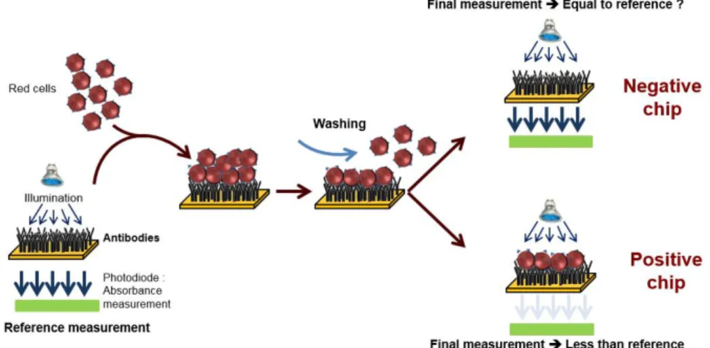
This top-down approach was employed to design an automated device used to perform the ultimate blood compatibility test at the patient’s bed-side in the field of blood transfusion safety [17, 18]. It was first applied to the case of ABO compatibility [19] and more recently to the case of Rhesus compatibility (experimental results given in this communication). The devices is based on biochips (bio-receptors) grafted with either anti-A or anti-B antibodies as seen in figure 1.
Figure 1. Principle of red cells capture at the surface of an immuno-biochip. Conventional SPR biochips are
coated with anti-A and anti-B antibodies (for ABO compatibility) or anti-D antibodies (for Rhesus compatibility). Blood to be tested is applied onto the bioreceptor and washed. Red cells are captured when an antigen-antibody reaction occurs (positive chips). When no capture occurs, biochips are negative. Detection of the capture is based on optical absorption. Figure adapted from [19].
When blood (either patient’s whole blood or red cells concentrate) is applied to the bioreceptor, antigen-antibody reaction may occur. When red cells are captured (antigen-antibody recognition), biochips are said positive. Conversely, when red cells are not captured, biochips are said negative. Capture detection is based on optical absorption of red cells. It consists in measuring the biochip transmission before and after
blood is applied and washed. Difference in transmissions allows detecting captured red cells. This difference is normalized by the transmission before blood is applied so that the actual measure is the optical absorption of the biochip.
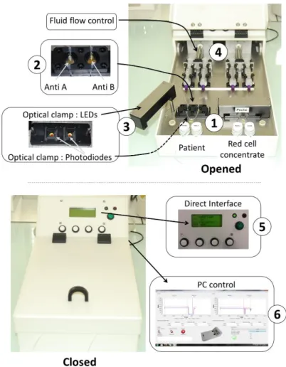
Figure 2 shows the automated device developed according to the above described principle in the case of ABO compatibility test. The heart of the system is the couple of disposable cartridges shown on the figure (parts 1). Two cartridges are used. One is used to test the patient’s blood, the other one is used to test red cells to be transfused. Two biochips are inserted in each of the disposable cartridges (parts 2). One biochip is coated with anti-A antibodies, the other one with anti-B antibodies. In this way, absorption measured at the 4 biochips allows controlling the ABO compatibility between red cells to be transfused and patients. For this, an optical clamp (parts 3) is located both in the rotatable arms (400 nm wavelength LEDs) and in the device body (photodiodes with enhanced sensitivity at 400 nm wavelength). Fluids (patient’s blood, red cells to be transfused and physiological serum used to wash biochips) are driven via motorized syringes (parts 4). The embarked software measures the transmittance of the biochips before and after the reaction process and simply applies the ABO compatibility rules. The software is also used to control fluid flows. A human-machine interface allows programing the fluid flows and optical reading (part 5). It also displays the compatibility result. All recorded data can also be recorded and stored in an external computer
via an USB port (part 6). Programing fluids flows is only used during the experimental period. For use at the
hospital, fluid flows are set to fixed value determined experimentally. They are not adjusted by medical staff.
Figure 2. Views of the automated device. Top views: device opened. Closer views of the biochips (parts 1 and
2), optical clamp (parts 3) and fluid flow control (parts 4). Bottom: device closed. Closer views of the direct human machine interface for clinical staff users (part 5) and USB connection to a PC for experimental studies during the device set-up (part 6). Figure adapted from [20].
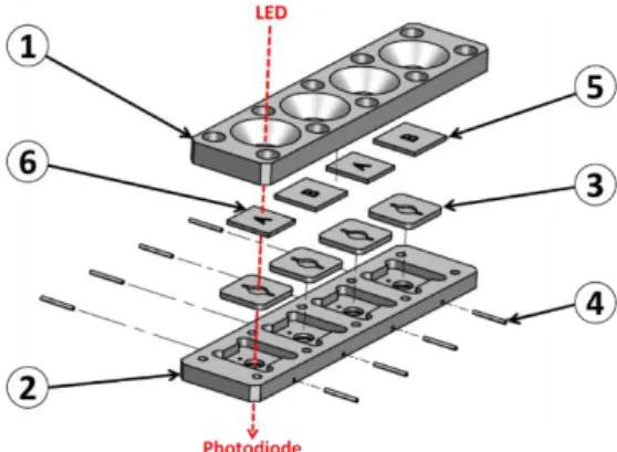
Illustrating our opinion that the top-down approach is profitable to a rapid device development, we must mentioned that the entire device was designed using conventional Computer Assisted Design software. It was fabricated using CNC (computer numerical control) machines available in the industry. Cartridges were designed as shown in figure 3. In this example, a cartridge with 4 biochips is represented.
However in the practical realization shown in figure 2, 2 cartridges bearing 2 biochips must be used in order to fully separate parts of the device concerning the patient and parts concerning the red cells to be transfused. The body of the cartridge is made of 2 complementary polycarbonate parts (parts 1 and 2 in the figure). Apertures allow optical reading. Molded silicone 50 shores Q74750 seals constitute the reaction chambers (parts 3). Dimensions and shape of the reaction chamber is directly inspired from those used in conventional SPR devices. Seals are also designed to ensure the junction between stainless steel tubing (parts 4) and biochips (parts 5 and 6 for anti-B and anti-A biochips respectively). Biochips are conventional SPR biochips. They consist of Cr/Au coated pieces of glass. Note that transparent polycarbonate can also be used to fabricate the biochips as it will be the case in the second example below.
Figure 3. Design of the disposable cartridges. Parts 1 and 2: body of the cartridge (polycarbonate). Part 3: silicon
seals and reaction chambers (silicon). Part 4: stainless steel tubing. Parts 5 and 6: biochips (SPR like biochips).
The devices was successfully tested using both whole blood and red cells concentrates in the case of ABO compatibility. Samples were absolutely non-prepared. Nearly 300 tests have been performed and results showed a specificity of 97.9% and a sensitivity of 99.3%. Wrong results were due to problems which occurred during the biochips fabrication. However, because the device was fabricated using conventional industrial machining techniques, such wrong results should be avoided by means of actual industrial fabrication obeying to high level quality controls.
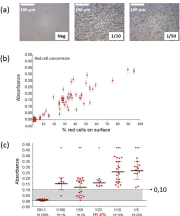
The device was also successfully tested in the case of rhesus compatibility. Figure 4 shows the results obtained in this case. Figure 4(a) shows a picture of a negative chip together with pictures of positive chips with red cell concentrates diluted at 1/10 and 1/50. It is clearly seen that the surface is not fully covered with red cells compared what was presented in [19]. The absorption evolves linearly with the percentage of the biosensor’s surface covered with red cells (figure 4(b)). Also, setting a positive absorption threshold at 0.1 allows using the device with hematocrit levels as low as 4% (figure 4(c)).
Figure a. Experimental results concerning Rhesus compatibility. (a) Pictures of negative and positive biochips
(red cell concentrate diluted at 1/10 and 1/50). Positive biochips are partially covered with red cells. (b) Optical absorbance vs. percentage of the surface covered with red cells. (c) Absorbance vs. hematocrit levels. A threshold set at 0.10 allows detecting red cells capture with 4% hematocrit blood.
To summarize this section and to illustrate our opinion, we have presented studies concerning ABO and RH1 compatibility. The top-down design procedure was employed to directly fulfill medical requirements. Conventional CAD and industrial machining was used to fabricate a proof-of-concept device which can be easily adapted for use at the patient’s bedside. Insertion of the device in the transfusion line was designed in collaboration with transfusion nurses at Besançon University Hospital. This ensured that the proposed device is in accordance with gesture made on a routine basis in clinical situations. The medical device proposed in this section does not require specific training. Experimental results were obtained in the case of ABO and Rhesus compatibility situation. Compatibility test duration is of the order of a few minutes, i.e. the same duration as for conventional and manual compatibility test. Similar concept can be directly adapted to other immunological incompatibility situations. Note that aspects concerning the identity vigilance (identity of the patient, red cells to be transfused and traceability of the actions conducted) is also under study.
2. A second example in the field of virus screening
One major constraints of working with non-prepared samples is the presence of relatively large particles present in the raw sample to be analyzed. These particles may sediment onto the bio-receptor’s surface, hence jeopardizing experiments. One advantage which is common to bottom-up and top-down approaches concerns the fact that fluids are flowing in the interaction chambers, conversely to what is made in ELISA like devices. This fluid flow drastically reduces sedimentation and non-specific interactions and leads to enhanced performances. In what follows, we address the advantage that fluidic systems exhibit compared to static (ELISA-like) methods.
We investigated the use of complex raw samples in studies concerning human cytomegalovirus (HCMV) screening in native breastmilk [21]. Basic principle is described in figure 5. Here, biochips are made with polystyrene plates and not with gold coated pieces of glass as it was the case in the previous section (Maxisorp plates from Nunc). The Maxisorp technology consists of polystyrene plates treated in order to enhance proteins coating. HPAb are incubated overnight at 4°C in carbonate buffer. Rinsing with Phosphate Buffer Saline (PBS) allows saturating the biochips surface using Bovine Serum Albumin (BSA).
Artificially infected (or not) raw milk is applied onto the bioreceptor’s surface. HCMV is captured by specifically developed antibodies (HPAb: Human polyclonal antibodies). Once capture is completed, anti-CMV antibodies coupled to HorseRadish Peroxidase (HRP) are applied onto the biochip. When the HRP substrate is added, the solution color first turns blue. An acid-base reaction (H2SO4 at 0.4 N vol/vol) is used
to stop the reaction. At this moment, the solution color turns yellow.
Figure 5. ELISA-like virus detection. HCMV: Human Cytomegalovirus. HPAb: Human Polyclonal
Antibodies. HRP: Horseradish peroxidase. When the HRP substrate is added, the solution color first turns blue. An acid-base reaction is used to stop the reaction. At this moment, the solution color turns yellow.
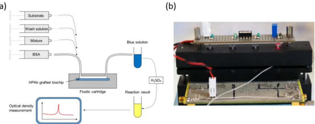
Experiments were conducted using a laboratory model inspired from what was originally developed for blood transfusion safety experiments. Cartridges corresponding to those represented above but containing polystyrene biochips were used. Bioreceptors were grafted with HPAb as above mentioned. Sequential reagent injection is described in figure 6 (a). Fluids were driven using motorized syringes. Figure 6 (b) shows the laboratory model. This model was originally design to test raw milk and to directly measure the optical absorption of the blue colored solution. For this a red LED is used for optical absorption measurement of the blue solution. However, the goal being to compare the performance of this device with performance of conventional ELISA, optical reading in the cartridge was not performed during the test.
Figure 6. Experiments using native breastmilk with the laboratory model. (a) Sequential injection of
reagents. Mixture holds for “artificially infected-milk / HRP coupled anti-CMV antibodies” in a synchronous sandwich experiment.
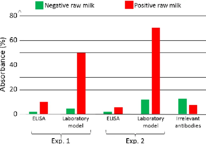
For comparison purpose, two parallel experiments were conducted. The first experiment used the laboratory model. Simultaneously, ELISA experiments were conducted using a similar synchronous sandwich protocol. Absorption measurement results concerning both experiments are given in figure 7. Difference between experiments 1 and 2 can be attributed to variations of the fluidic arrangement as explained below. Bars corresponding to “irrelevant antibodies” refer to one experiment performed using the anti-LAG3 antibodies.
Figure 7. Optical absorbance obtained with native breastmilk artificially infected with HCMV. Virus level:
6 ng/µL. Comparison static vs. fluidic using ELISA and laboratory model respectively. Absorbance measured at 450 nm wavelength using an optical spectrometer.
Concerning absorbance measured using the conventional ELISA technique, it can be observed that the ratio “positive/negative” is relatively small. However, the most important feature to be noted is the fact that doing the same experiment with irrelevant antibodies leads to higher absorbance values. This shows that it is not possible to detect HCMV in native breastmilk which has not been previously prepared. The main reason for this is that ELISA measurement is performed in static conditions. Sedimentation of raw milk components (proteins and more probably fats) onto the capture antibodies prohibits antibody/antigen recognition and jeopardizes results.
On the contrary, when experimenting in fluidic conditions, this shielding effect does not exists. Furthermore, fluidic conditions increase the antibody/antigen recognition probability. This can be clearly observed in figure 7 with bars representing the absorption achieved using the laboratory model. In this case, the ratio “positive/negative” is 5 for experiment 1 and 6.4 for experiment 2. Furthermore, the time required to perform the experiment with the laboratory model is half the one required in ELISA.
In the experiment presented here, addition of the substrate make the solution turn in blue. The reaction is stopped outside the laboratory model using sulfuric acid. This make the solution turn yellow. We tried to measure the absorption due to the blue color of the solution directly in the model by means of the red LED visible in figure 9. We did not succeed because of various difficulties. The fluidic arrangement was not stable. Indeed, changing the injected reagent by changing syringes often produces bubbles in the tubing. We recall that the tubing close to the reaction chamber is not particularly attached to any part of the laboratory model. Presence of bubbles jeopardizes the optical reading. Also, reaction of the substrate lasts for about 30 min and the optical absorption is relatively weak. Great attention must then be paid to the electro-opto-mechanical stability of the device. The laboratory model was not satisfactory regarding these issues. Finally, photodiodes were poorly isolated from variation of the ambient light. Such variations are likely to occur during a 30 min experiment. Constraints concerning electronic, optic, mechanic and fluidic were not so drastic in the case of red cells capture. Indeed in the case of red cells, the absorption is very high and experiments lasts for about 5 min only. These experimental difficulties led us to design a much more stable integrated device presented in figure 8.
Figure 8. Integrated device designed to enhance overall stability of the laboratory model. Part 1: double
polystyrene biochip. Part 2: silicon seal also forming the reaction chamber. Part 3: inlet and outlet apertures. Part 4: commercial fluidic connectors. Part 5: 650 nm LED. Part 6: regulation aperture. Part 7: photodiode. Part 8: integrated driving and regulation electronics. Part 9: light isolation O-ring.
Here, 2 polystyrene biochips are used (part 1 in the figure). Both are grafted with HPAb. In this way, the surface concentration of captured viruses is doubled as well as the optical absorbance (bottom left of the figure). Biochips are separated by a silicon seal (part 2) which also forms the reaction chamber. Stops are machined in the device body in order to guaranty a constant reaction chamber height from one experiment to another one (not shown in the figure). Inlet and outlet apertures are machined in the upper biochip (part 3). Reagent are driven to the reaction chamber using commercially available fluidic connector (part 4) and rigid tubing. In this way, apparition of unwanted bubbles when switching between reagents is avoided. A 650 nm LED is used to illuminate the biochips (part 5). Light is somehow guided through the device by means of 2 mm diameter drillings. An aperture (part 6) is machined in the device body. It is used to capture a part of the emitted light for optical emission power regulation. The optical signal is measured using a photodiode with maximum sensitivity in the red wavelength region (part 7). Driving and regulation electronics is integrated in the device body (part 8). Regulation is used to compensate for optical intensity variations due to both thermal variation and influence of the ambient light. Ambient light is further attenuated by means of the O-Ring (part 9).
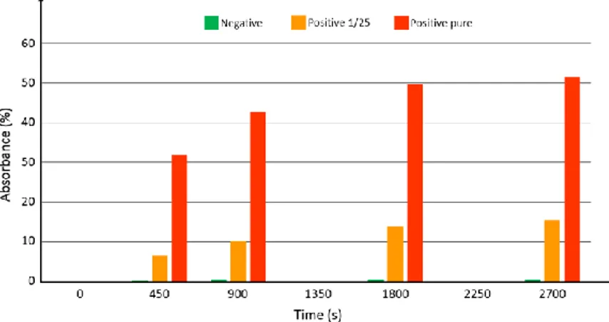
At the time when this integrated device was ready for use, native breastmilk sample were not available from the hospital. Tested samples consisted of commercial antigens (Diasorin) mixed with detection antibodies. Three samples were prepared: 1 negative sample, 1 sample with the antigen diluted at 1/25 and 1 pure sample (antigen not diluted). In the same manner as what was done in previous sections, synchronous sandwich configuration was used. Fluid flow and volumes were the same as what was described above. In this case however, no acid was used to stop the reaction with the substrate. Figure 9 shows the absorbance measured at time t=0, 450 s, 900 s and every 900 s after.
Figure 9. Absorbance measured at time 0, 450, 900, 1800 and 2700 s. Green: negative sample. Orange:
positive sample with antigen diluted at 1/25. Red: positive sample with pure antigen.
The logarithmic behavior of the optical absorbance is clearly visible. Experiments are ongoing in order to continuously record the optical signal. Looking at figure 12, it can be estimated that the substrate reaction stops after more than 1 hour. However, looking at the absorbance differences between the 3 samples, it is reasonable to assess that using such a device, much shorter experimental times should allow accurate determination of the viral load. Indeed, the sensitivity appears to be relatively high (no numerical data available at this point). At time zero, the intensity delivered by the photodiode is 11.5 µA. The detection noise level was measured to be about 8 nA. A rapid calculation shows that using this well controlled sample phantom, dilution levels as high as 4500 should still be detectable. However, it is expected that the viral load in actual native breastmilk samples will be quite low. A clinical trial using native milk of lactating mother of premature infants should start before the end of 2017.
To summarize this section,we have presented studies ongoing concerning the detection of HCMV in non-prepared breastmilk. Again, the top-down approach was used to fit as close as possible the usability constraints dictated by end-users. In this example, the ability to work with complex non-prepared samples
constitutes a key point for the actual development of this immuno-combined medical device. We already highlighted the fact that in clinical situations, medical staff are not meant to prepare samples as it could be done in a biology laboratory by specially trained members of staff. The case of HCMV screening is even more emblematic of the need to avoid sample preparation. Indeed, the final goal of these studies is to develop a Rapid Diagnostic Test (RDT) which will be used at home by mothers at the moment when the HCMV excretion is maximum. Although only pre-studies concerning the sandwich assay are partially completed today, a laboratory model and a more integrated device built using conventional industrial machining capabilities were designed. This “end user point of view” approach ensures that, not only the sandwich assay definition but furthermore the sandwich assay working in such pre-industrial device, the best probability of success are given to the final medical device.
Conclusion
In this opinion communication, we have presented results concerning steps toward immuno-combined medical devices which are meant to be used in clinical situations. Immuno-assays are often developed for use in biology laboratories by specifically trained members of staff. Micro-fabrication techniques are proposed in order to increase the number of functions at the surface of so-called µTAS. The main idea is not only functions integration but also the ability to work with extremely small samples. In these microfluidic systems, the fluidic configuration is advantageously put to profit in order to enhance the measurement sensitivity and to improve the recognition probability of reacting biological species. The high density integration potential of such devices is sometimes considered as a key point to the transfer to clinical situation. This results from a bottom-up approach or a “researcher point of view” approach.
However, in clinical situations, sample volume is rarely an issue and fluidic configuration is often a very interesting option for the above-mentioned reasons. In this case, a top-down approach (the “end-user point of view”) is often a better option for designing a medical device which can be used at the hospital or at home by non-specifically trained people. This requires that the biological samples under test do not undergo any preliminary preparation.
We have presented studies concerning blood transfusion safety and HCMV screening both at the hospital and at home. Both projects are at different development levels. However, in both cases, a bidirectional translational approach has been privileged. To summarize, studies concerning blood showed that using this design method, a prototype which can be used by non-trained people and in an automated way was fabricated and tested. The prototype was fabricated with conventional industrial machining techniques and was successfully employed with complex and non-prepared biological samples. Concerning the HCMV screening, the same design approach was used to fabricate devices able to work with raw breastmilk samples. The fluidic configuration is indeed the only way to detect HCMV in native breastmilk as it was demonstrated when comparing fluidic to static environments.
To conclude, it should be noted that what was presented in this paper using immuno-assays can directly be transposed to other target/probe sensors when no sample preparation is required.
Acknowledgements
These studies were partially funded by Besançon University Hospital (APICHU operations), by the EFS (grant DECO-13-0128), the INSERM-CNRS (patent file CNRS/REF: 02682-V), OSEO and the University of Franche-Comté (grant A1105005I). This work is developed in the frame of the French RENATECH network and the Biom’@x transversal axis at FEMTO-ST.
Conflict of Interest
There is no conflict of interest.
References
1. Vidal, J.C., Bonel, L., Ezquerra, A., Hernández, S., Bertolín, J.R., Cubel, C., Castillo, J.R., 2013, Electrochemical affinity biosensors for detection of mycotoxins: A review. Biosensors and Bioelectronics, Vol. 49, pp. 146-158.
2. Das, A.P., Kumar, P.S., Swain, S., 2014, Recent advances in biosensor based endotoxin detection. Biosensors and Bioelectronics, Vol. 21, pp. 62-75.
3. Kaisti, M., 2017, Detection principles of biological and chemical FET sensors. Biosensors and Bioelectronics, Vol. 98, pp. 437-448.
4. Dzyadevych, S.V., Soldatkin, A.P., Korpan, Y.I., Arkhypova, V.N., El’skaya, A.V., Chovelon, J.M., Martelet, C., Jaffrezic-Renault, N. , 2003, Biosensors based on enzyme field-effect transistors for determination of some substrates and inhibitors. Anal Bioanal Chem, Vol. 377, pp. 496–506.
5. Yao, K., Zhu, Y., Yang, X., Li, C., 2008, ENFET glucose biosensor produced with dendrimer encapsulated Pt nanoparticles. Materials Science and Engineering, Vol. 28, pp. 1236–1241.
6. Rocha-Gaso, M.I., March-Iborra, C., Montoya-Baides, A., Arnau-Vives, A., 2009, Surface Generated Acoustic Wave Biosensors for the Detection of Pathogens: A Review. Sensors, Vol. 9, pp. 5740-5769. 7. Biomedical photonics handbook, Tuan Vo-Dinh, editor in chief, CRC Press, ISBN: 0-8493-1116-0. 8. Mateescu, A., Wang, Y., Dostalek, J., Jonas, U., 2012, Thin Hydrogel Films for Optical Biosensor
Applications. Membranes, Vol. 2, pp. 40-69.
9. Olga, K., Khalil, A., Edric, G., Arousian, A., 2017, Review on State-of-the-art in Polymer Based pH Sensors. Sensors, Vol.7, 3027–3042.
10. Weller, M.G., 2013, Immunoassays and Biosensors for the Detection of Cyanobacterial Toxins in Water. Sensors, Vol. 13, pp. 15085-15112.
11. Luka, G., Ahmadi, A., Najjaran, H., Alocilja, E., DeRosa, M., Wolthers, K., Malki, A., Aziz, H., Althani, A., Hoorfar, M., 2015, Microfluidics Integrated Biosensors: A Leading Technology towards Lab-on-a-Chip and Sensing Applications. Sensors, Vol. 15, pp. 30011–30031.
12. Ali, M.A.; Srivastava, S.; Solanki, P.R.; Reddy, V.; Agrawal, V.V.; Kim, C.; John, R.; Malhotra, B.D., 2013, Highly efficient bienzyme functionalized nanocomposite-based microfluidics biosensor platform for biomedical application. Sci. Rep., Vol. 3, pp. 2661.
13. Golberg, A.; Linshiz, G.; Kravets, I.; Stawski, N.; Hillson, N.J.; Yarmush, M.L.; Marks, R.S.; Konry, T., 2014, Cloud-enabled microscopy and droplet microfluidic platform for specific detection of Escherichia coli in water. PLoS ONE, Vol. 9, pp. 4–12.
14. Choi, K.; Kim, J.-Y.; Ahn, J.-H.; Choi, J.-M.; Im, M.; Choi, Y.-K., 2012, Integration of field effect transistor-based biosensors with a digital microfluidic device for a lab-on-a-chip application. Lab Chip, Vol. 12, pp. 1533–1539.
15. Cui, F., Rhee, M., Singh, A., Tripathi, A., 2015, Microfluidic Sample Preparation for Medical Diagnostics. Annual Review of Biomedical Engineering, Vol.17, pp. 267-286.
16. Gaiffe, O., Pieralli, C., Tavernier, L., Pazart, L., Wacogne, B., 2013, Reverse translational research: how clinical trials on fluorescence imaging for vocal cord cancer fuels fundamental research. Proceedings of the International Conference on Biomedical Electronics and Devices, Barcelona, Spain, pp. 282-287. 17. Pazart, L., Wacogne, B., Pieralli, C., Boireau, W., Morel, P., 2009, SECURE PERFUSION SYSTEM, N°
WO2011055031.
18. Pazart, L., Wacogne, B., Pieralli, C., Boireau, W., Morel, P., 2009, DEVICE FOR TAKING A SAMPLE OF A BODY FLUID AND METHOD FOR IMPLEMENTING SAME, N°WO2011055029.
19. Charrière, K., Rouleau, A., Gaiffe, O., Fertey, J., Morel, P., Bourcier, V., Pieralli, C., Boireau, W., Pazart, L., Wacogne, B., 2015, Biochip technology applied to an automated ABO compatibility test at the patient bedside. Sensors and Actuators B, Vol. 208, pp. 67-74.
20. Karine Charrière, Jean-François Manceau, Pascal Morel, Véronique Bourcier, Wilfrid Boireau, Lionel Pazart and Bruno Wacogne, 2018, Test device for Blood transfusion safety: How acoustics can help preventing any red cells incompatibility, in Press, Proceedings of the International Conference on Biomedical Electronics and Devices, Funchal, Portugal.
21. S Py, A Guitton, F Lardet, N Marthouret, L Pazart, A Coaquette, W Boireau, G Thiriez, G Herbein and B Wacogne, DETECTING CYTOMEGALOVIRUS IN BREASTMILK: Towards a device for self-monitoring risks of postnatal infection, in Press, Proceedings of the International Conference on Biomedical Electronics and Devices, Funchal, Portugal.