Design and Testing of a Low-Cost Exoskeletal Trans-Femoral Prosthetic
Knee Device for Use in Developing Countries
by
Jared Asher Sartee
SUBMITTED TO THE DEPARTMENT OF MECHANICAL ENGINEERING IN PARTIAL FULFILLMENT OF THE REQUIREMENTS FOR THE DEGREE OF
BACHELOR OF SCIENCE IN MECHANICAL ENGINEERING AT THE
MASSACHUSETTS INSTITUTE OF TECHNOLOGY
JUNE 2009
02009 Jared Sartee. All rights reserved
ARCHIVES
MASSACHUSETTS INSTIUTE OF TECHNOLOGY
SEP
1
6
2009
LIBRARIES
The author hereby grants to MIT permission to reproduce and to distribute publicly paper andelectronic copies of this thesis document in whole or in part in any medium now known or hereafter created.
/
Signature of Author:
Department of Mechanical Engineering
/
/
May 8, 2009Certified by:
Hugh Herr Associate Professor of the Media Arts and Sciences Thesis Supervisor
Professor J. Lienhard V Collins Professor of Mechanical Engineering Chairman, Undergraduate Thesis Committee Accepted By:
Design and Testing of a Low-Cost Exoskeletal Trans-Femoral Prosthetic
Knee Device for Use in Developing Countries
by
Jared Asher Sartee
Submitted to the Department of Mechanical Engineering on May 8, 2009 in Partial Fulfillment of the Requirements for the degree of Bachelor of Science in
Mechanical Engineering
ABSTRACT
Prosthetic devices are designed for amputees in developed countries, made with materials, mechanisms, and research budgets prohibitive to individuals and communities in developing countries. A prosthetic knee for trans-femoral amputees is developed at MIT and tested on patients at the Jaipur Foot Organization in Delhi, India. By using kinematic models of the knee, information was gathered on the feasibility of incorporating a stance-flex knee flexion mechanism in the design. Results show an increase in the flexion torque required to buckle the device in stance phase, resulting in a more reliable gait for the amputee. It is concluded that the prototype designed is a feasible alternative to current knee technology present in developing countries, although incorporation of a stance-flex mechanism is not possible within the confines of the current design.
Thesis Supervisor: Hugh Herr
Table of Contents
Abstract ... 2
Table of Contents ... ... 3
1 Introduction... ... 4
1.1 Requirements for an Appropriate Prosthetic Design ... 5
1.2 Utility ... ... 5
1.3 Cost... ... 6
1.4 Robustness ... ... ... ... ... ... ... 7
2 Background... ... ... ... ... 2.1 Prosthetic Leg Technology ... 8
2.2 Biomechanics of Normal Human Gait ... 9
2.3 Jaipur Foot Organization ... 14
3 Development of the Exo-Knee ... 15
3.1 Exo-Knee Version 1 & 2... ... ... 16
3.2 Exo-Knee Version 3... 19
3.3 Design Details ... 21
3.4 Socket Attachment Technique ... 23
3.5 Shank Integration ... ... ... 25
3.6 Foot Selection ... . ... ... ... ... 26
4 Modeling the Exo-Knee ... 27
5 Discussion of Findings... .... ... ... ... .. ... 29
6 C onclusion ... 31
7 Acknowledgements ... ... 32
1 Introduction
The development of a prosthetic device from the perspective of a student who studies
mechanical engineering is, at first glance, a very straightforward problem. The skill set of
someone trained in static load testing and kinematic analysis is very compatible with the
development of a system which emulates the human body's natural movements. Similarly, testing and dynamic analysis of a new prosthetic limb is relatively straightforward. However, the
nuance in development of such a device is found in the designer-patient interaction which takes
place before it is even conceived.
The focus of this thesis will be to understand the specific factors which make a prosthetic device functional for the intended user, as well as develop a method for appropriate testing
procedures and analysis of the device. In order to accomplish the latter goal, an extensive
research study has been conducted for the purpose of analyzing factors which weigh strongly into the development of a low-cost prosthetic device.
Current prosthetic technology in the developing world is limited in its complexity
because of affordability and durability constraints. The vast majority of devices in use for
trans-femoral amputees are classified as single-axis, stance-control knees, but do not incorporate a
weight-activated stance-lock or stance-flex feature. This is a major shortcoming for elderly and less active users because frequent falls characteristic of patients in this demographic necessitate
an additional stance-control feature. Work has been done to overcome this problem, designing a
device simple enough to manufacture inexpensively with existing technology and materials available in the region, as well as durable enough to withstand a normal lifecycle of 3-5 years of daily use.
1.1 Requirements for an Appropriate Prosthetic Design
In order to more clearly define what is meant by appropriate technology as it applies to
prosthetic design, a demographic is chosen which encompasses the broadest need for assistance.
In the case of prosthetics, the broadest need falls in the third world, where less than ten percent
of the world's designers focus on over ninety percent of the world's amputees. Because of this
phenomenon, there is a large gap in resources available to designers, as well as practical solutions which benefit users in the third world.
Three main factors drive development of a prosthetic device: utility, cost, and robustness.
Utility; the ability of a prosthetic device to enable the user to return to activities necessary for
daily life, is the most important characteristic of a design. Cost determines the overall acceptance of the device in a patient market, and is commonly the main factor when deciding
which options are available to the amputee. Robustness; the ability of the device to function in a
variety of working environments, withstand large shock forces, and variations on intended use, is
perhaps the most difficult to quantify of the three driving factors. Although these three metrics,
utility, cost, and robustness, factor into design of both first and third-world devices, their individual roles vary greatly depending on the target patient group.
1.2 Utility
Utility is a characteristic that carries very different connotations depending on whether one is comparing a first or third-world prosthetics device. Prosthetic solutions in developed countries may take the form of multiple limbs or interchangeable components, each optimized
for a specific activity. Other times, the decision is made to upgrade a user's device based on its
ability to restore a greater level of mobility for more active patients.
In developing countries, multiple components for prosthetic systems are not viable
options. In most cases, high cost prohibits the distribution of more than one device to any
individual. The device must be versatile enough to encompass the wide range of activities it may be used for, from farming and agriculture to manufacturing facilities, yet it must be refined
enough to provide sufficient performance in each of these applications. There is very little
likelihood for expansion of a prosthetic line, so the device must fit the needs of a variety of users. In considering the design of a device, utility of the prosthesis must be maximized
effectively. Considering what functions the user will need at work, home, and while commuting is the first and most important part of the design process.
1.3 Cost
In the United States, retail price for a prosthetic device system ranges from $3,000 to
$40,000, depending greatly on functionality and the ability to return an individual to the activity level required. Cost becomes an essential consideration for patients with an average income of
$2/day, the typical value for a user in a developing community. These patients generally have no source of disposable income or support from a third-party buyer such as an insurance company.
The scope of this research is limited to devices which are affordable to the average user in a
developing country.
For an amputee who is making under $1,000 per year, a device that costs over $20 is a large financial burden, and a device costing over $50 is generally unattainable. For this reason, the rolled up parts and labor cost of a prosthetic device system must be on the order of $10-50,
depending on distribution channels and clinic operational costs. The device designed for
distribution at Jaipur Foot Organization in Delhi, India, a transfemoral knee prosthesis, will cost approximately $30, inclusive of assembly costs and patient care. Combined with a full leg system, this knee becomes a reasonable option as a replacement for the current technology at
JFO.
1.4 Robustness
Robustness determines the longevity and durability of the design, as well as the versatility of its potential application. The typical lifespan of a device in developing countries
varies widely, but when well-designed, should give the patient at least 3 years of reliable usage.
A robust design will require that the device be tested both cyclically and for maximum load
strength. Cyclic testing represents day-to-day fatigue, which will accumulate over time, and helps to identify weak points in the device that are likely to cause failure. Maximum load
strength must be approximately three times body weight in order to withstand any jump, fall, or
other shock the device might be subjected to.
2 Background
In order to focus the analysis of types of prosthetic devices that have already been
implemented in developing countries, and brief overview of prosthetic leg technology is given. Furthermore, figures and graphs of the biomechanics of human gait are presented to demonstrate
what functional and kinematic needs the new device must fulfill. Background information on Jaipur Foot Organization, known commonly in India as Bhagwan Mahaveer Viklang Sahayata Samiti (BMVSS), is the world's leading supplier of artificial limb devices, and has developed a
broad distribution network through India. Their coordination and technical support is what made
development of the Exo-Knee device possible.
2.1 Prosthetic Leg Technology
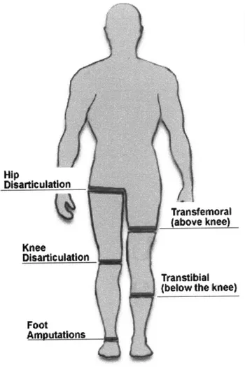
Various prosthetic devices are made to cover all levels of amputation in an individual.
Figure la shows the different leg amputation levels a patient may be left with [1]. Two main
factors determine the prescription for a prosthetic device; level of amputation and level of
expected ambulation.
Level of leg amputation may range from symes (ankle amputation), to transtibial
(between ankle and knee), knee disarticulation (amputation of the lower leg, with preserving the
knee), transfemoral amputation (between knee and hip), and hip disarticulation (removal of the
entire leg). Level of expected ambulation depends greatly on the activity level of an amputee before undergoing surgery, and is generally rated on the Healthcare Common Procedure Coding
System (HCPCS) scale, Figure lb [2]. By classifying an individual on this scale, a prosthetist is
able to prescribe an appropriate device.
Leg prostheses are further broken down to the foot type and socket type they use. The entire leg system comprises of a foot, shank (lower leg section), knee (in the case of transfemoral
amputees), and socket system. Additional features are often incorporated, such as torque
absorbers and force absorbers, as well as suction devices to maintain negative pressure on the
socket, but these devices are generally reserved for patients being treated in developed countries and are prohibitively expensive for amputees in third-world communities.
Transfemoral
(above knee)
Transtiblal
(below the knee)
Foot
Amputations
Figure la Leg amputation levels.
amputations are included under
Amputations." [1]
Symes "Foot
K Modifiers for Patient Functional Levels
KO-Functional Level 0: The patient does not have the ability or potential to ambulate or transfer safely with or without assistance and a prosthesis does not enhance the quality of life or mobility.
K--Functional Level 1: The patient has the ability or
potential to use a prosthesis for transfers or ambulation on level surfaces at fixed cadence. Typical of the limited and unlimited household ambulatory.
K2-Functional Level 2: The patient has the ability or potential for ambulation with the ability to traverse low-level environmental barriers such as curbs, stairs or
uneven surfaces. Typical of the limited community ambulatory.
K3-Functional Level 3: The patient has the ability or
potential for ambulation with variable cadence. Typical of the community ambulatory who has the ability to traverse most environmental barriers and may have vocational, therapeutic or exercise activity that demands prosthetic utilization beyond simple locomotion. K4-Functional Level 4: The patient has the ability or potential for prosthetic ambulation that exceeds basic ambulation skills, exhibiting high impact, stress or energy levels. Typical of the prosthetic demands of the child, active adult or athlete.
Figure lb HCPCS amputee ambulation
level chart. The majority of amputees targeted for the Exo-Knee are in the K2-K3 range. [2]
2.2 Biomechanics of Normal Human Gait
Analysis of the performance of a prosthetic device is grounded by how closely it is able
to replicate the kinematics of normal human gait. If the device cannot reproduce the normal
functions of an arm and hand, or provide the user with normal gait, it will not be an effective rehabilitation tool. Scope of the analysis will be limited to gait and the gait cycle, as this is one of the simplest and most effective ways to quantitatively analyze the kinematic performance of a leg prosthesis.
Disarticulation
Knee
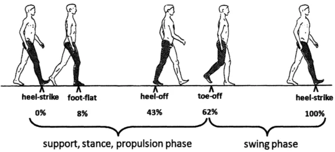
Gait is the manner of walking of a human at a normal cadence, and can be quantified by
the measurement of joint angles in the leg of interest during normal walking. Figure 2 shows the
normal human gait cycle, defined as the time between heel strikes of the same foot during walking [3]. The cycle is divided into two phases, stance and swing. Stance phase occurs while
the foot is in contact with the ground, swing phase when the foot is suspended in air. Events within the gait cycle are referenced by the percentage of one full cycle that has progressed. On
average, foot flat occurs at 8% gait cycle, heel-off during propulsion at 43%, toe-off at 62%,
followed by heel strike at 100% to complete the cycle.
heel-strike foot-flat heel-off toe-off heel-strike
0% 8% 43% 62% 100%
support, stance, propulsion phase
swing phase
Figure 2 The normal gait cycle as defined by heel strike of the right foot to the following heel
strike of the same foot. Stance phase occurs while the foot is in contact with the ground, swing phase when the foot is suspended. [3]
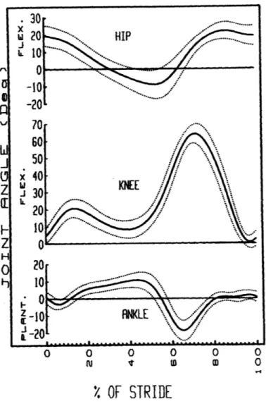
Further analysis of gait characteristics in normal walking indicates a high consistency of
joint angles at the hip, knee, and ankle at self selected walking cadences. Figure 3 shows a
representation of these joint angles, with the solid line representing mean values, and dotted lines representing +/- 1 standard deviation from the mean [4]. Remarkably, mean values do not vary
greatly from person to person, and thus can be used as a metric for determining normal gait in amputees.
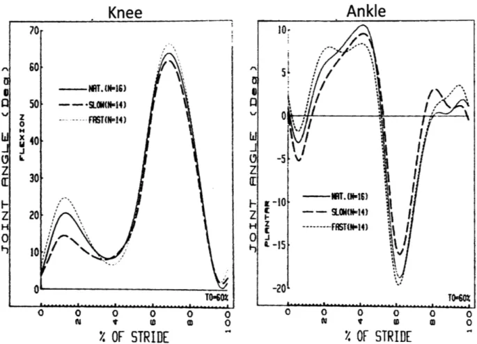
Another notable characteristic gait is that joint angles in the knee and ankle do not vary
greatly with walking speed, however notable differences between slow, natural, and fast
cadences can give a prosthetic designer intuition about the patient's requirements for the device. For example, in Figure 4, mean joint angles at the knee and hip joint are plotted for slow, natural,
and fast cadences [4]. Although little variation is observable between speeds, an increase in
stance phase knee flexion occurs proportional to an increase in walking speed at the knee. The joint angle increases for higher shock absorption capacity in the knee as speed increases. Design
considerations may be relevant based on these trends.
A similar shock absorption characteristic can be inferred from the proportional decrease
of ankle dorsiflexion during foot flat in stance phase. Furthermore, an increase in ankle
dorsiflexion during swing phase indicates the natural tendency of the foot to avoid contact with the ground until heel strike occurs, a characteristic that is generally designed for in prosthetic
0 0 0 0 0
'
OF STRIDE
Figure 3 Joint angles at the hip, knee, and ankle, respectively, versus percent gait cycle. Mean
values are in black, and dotted lines represent +/- 1 standard deviation from the mean. [4]
Certain biomechanical behaviors can be attributed to functional mechanisms for efficient
human gait. Beginning with heel strike, the controlled planarflexion of the ankle joint absorbs
the impact force of the subject as they transfer their weight from one leg to the other. As weight
is fully transferred towards the sound leg around 40% gait cycle, the ankle again planarflexes to provide propulsion of body mass to the opposing sound leg. Thus, the ability of the ankle to store energy in controlled planarflexion, and release it again in powered dorsiflexion, is the main mechanism of locomotion in the human leg.
Knee
Ankle
70 10 I) -- NR T. (NI16) II z 50 - SLOW-- w ... Z Z H ZH --- ffST(N-14) 0 0 -15K
0 -20 TO-60 TO6Z O O 0 0 0 0 0 0 0 0 0 0 i It w 0 i I tD M 0%
OF STRIDE
4
%
OF STRIDE
Figure 4 Mean joint angles for the knee and ankle, respectively, and slow, natural, and fast
cadences. Joint angles are normalized as a total percentage of gait cycle. [4]
Swing phase characteristics of the leg can be simplified, as long as extension of the knee joint does not cause the foot to make contact with the ground. In prosthetic devices, this is
usually achieved by returning the prosthetic ankle to 00 planarflexion.
In the knee joint, the main method of shock absorption is knee flexion after heel strike.
As the knee flexes, muscles dissipate the energy of the weight transfer until the foot is completely flat [5]. A large distinction exists in transfemoral prosthetic devices between those
which incorporate this biomechanical attribute, and those which do not. The decision to use a stance-flex or a stance-lock knee is made based on the activity level and functional requirements of the amputee.
2.3 Jaipur Foot Organization
Jaipur Foot Organization (JFO) of India is an NGO dedicated to the restoration of
movement in the physically disabled, especially those underrepresented within the community. The vast majority of amputees who are fitted with prosthetic devices have no means of affording
the high cost associated with bringing that device to market, and it is the mission of the JFO to provide prostheses free of charge to all who require them. JFO operates on an annual budget of
approximately 3 million USD, and obtains the majority of its funding from private grants.
Approximately 17% of the budget is contributed by the government of India. The organization
uses this budget to subsidize the cost of each prosthetic device and mobility aid for the recipient. With headquarters in Jaipur, India, JFO is able to distribute its devices to other central
offices in India, Mumbai, and elsewhere. Manufacturing is done in house at the Jaipur manufacturing facility, and locally available materials are purchased to hand-fabricate each foot,
joint, and orthodic device. JFO manages a clinic in Delhi, India, where patients are received and
diagnosed for the type of device needed [6]. A prosthetic technician then takes the patient's measurements, makes molds of the residual limb, and fabricates the socket in-house. The patient
is then fitted with the new device and their gait is observed to uncover any undesirable
pathologies. Patients are commonly treated in one business day, with transfemoral amputees taking an average of two days.
JFO provides a great service to its patients, and has treated over 60,000 physically
disabled people in its 35 years as an NGO [6]. Although prosthetic technology has moved forward at a consistent rate, solutions for amputees at JFO and in other parts of the third world
do not reflect the current advances in technology. It is for this reason that work is being done to
greatly accelerate development of prosthetic devices in developing countries.
3 Development of the Exo-Knee
During Spring 2008, the opportunity arose to start work on a prosthetic prototype with
Sanjeev Kumar, P&O, manager of JFO in Delhi, India. At the time of accepting this project, the need had been outlined for updating the design of the current solution for transfemoral amputees
treated by the organization. Up to the time of this research, the only device used by JFO has
been a single-axis, dynamically stable stance-lock device. The versatility of such a design has
been proven throughout its long history, but the utility of the device for users wanting to restore natural gait is inherently limited by design.
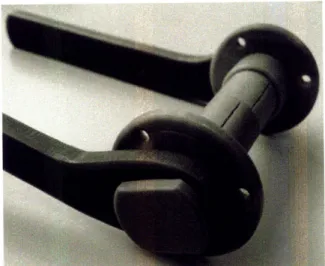
The single-axis, stance-lock device used by JFO is depicted in Figure 5a. The current
injection molded device is to the left, while the previously replaced device is right. Although the prostheses differ in manufacturing methods and materials, their function is the same: to provide a
locking moment during stance phase, resulting in a straight-leg gait during stance. This locking
moment is created by adjusting the prosthesis so that the axis of rotation at the knee joint is
posterior to the weight line in the sagittal plane. At toe-off, the ground reaction force is reduced
to zero, and the knee is allowed to flex for normal swing phase characteristics. Note in Figure 5a and 5b that each device can fit hose clamps around the stationary axle housing to vary the
Figure 5a Current exoskeletal prosthetic Figure 5b Device recently replaced by
knee joint used by JFO for majority current model, fabricated using variety of transfemoral amputees, manufactured by techniques with Oilone axle.
injection molding.
3.1 Exo-Knee Version 1 & 2
Sanjeev Kumar, who sought help in development of a stance-flex design for his patients,
visited MIT in Spring 2008 to help develop the new device. Through Developing World
Prosthetics (DWP), a non-profit organization founded to sustain the research and design of prosthetic devices for developing countries, a team of undergraduate mechanical engineers
including Cathy Mancuso, Karina Pikhart, Amy Qian, Carmel Dudley, and myself, was
assembled to redesign the Exo-Knee. Presented with Mr. Kumar's prototype of the Jupa Knee
system, shown in Figure 6, we were able to begin development on a device that met the needs of
Figure 6 Exo-Knee Version 1: Development of this prototype took place in Delhi, India, by
Sanjeev Kumar, P&O. The device incorporates the stance lock feature of the Jupa Knee by Otto Bock.
During the spring term of 2008, progress was made on a functional design for a
stance-flex version of the Exo-Knee. Although much work was done to develop a new prototype, and
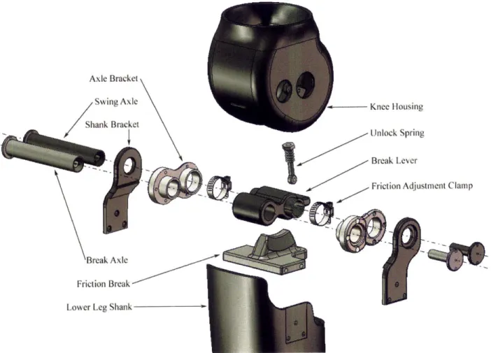
the design was presented in May at the MIT Museum, there were still various issues which prohibited functional tests. Figure 7 shows an exploded assembly view of the Exo-Knee V.2. Similar design elements to Version 1 were used; the emphasis of this prototype was to achieve stance-flexion functionality and demonstrate proof-of-concept.
Axle Bracket / Swing Axle Shank Bracket I - Knee Housing Unlock Spring - Break Lever Break Axle Friction Break Lower Leg Shank
Figure 7 Exploded view of Exo-Knee V.2. Shank and axle bracket is labeled only once, and
fasteners are not shown.
The Exo-Knee is modeled after a typical stance-control prosthetic knee, but uses friction
breaking to allow knee joint flexion of 15-25' during initial stance phase. The use of the stance-lock feature, typically seen in the Otto Bock Jupa Knee, as a stance-flex device was previously untested and attractive as a design choice for JFO because of the ability to reduce the overall part
count in the device by combining features. Fabrication of the prototype was done at the MIT
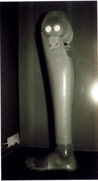
Media Lab with Steriolithography (SLA) technology. While the device was designed to demonstrate functionality, the hardware for attaching it to a socket for testing was not prototyped, which limited our analysis to simple proof-of-concept demonstrations. The first prototype is shown in Figure 8 below.
Figure 8 Exo-Knee Version 2: Final prototype of the knee before class presentations in May
2008. The prototype is functionally similar to the current design, but lacks structural stability or
components designed for manufacture.
3.2 Exo-Knee Version 3
Although Exo-Knee V.2 was capable of demonstrating stance stability locking with a
small ground reaction force, it lacked many of the functional requirements outlined at the beginning of the term. Reevaluation of the project goals allowed for a more detailed list of
* Stance flexion without buckling during loading
* Knee alignment adjustability for dynamic alignment on patients
* Extension assist mechanism for swing-phase control
* Exoskeletal design that allows for integration with current socket technology at JFO
* Injection moldable components made only with two-part molds
* Minimization of needed parts; both hardware and molded parts
All six metrics listed above affect the functionality of the new design, and only the last
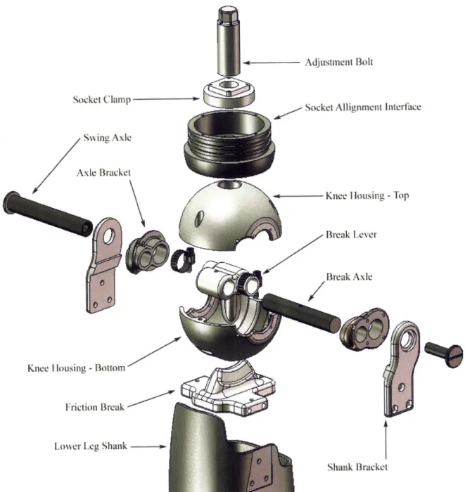
two are addressed by the previous Jaipur knee. To fulfill these requirements, a thorough redesign of each component was done. Figure 9 shows the third version of the prototype that
was brought to India for testing. It was designed as a stance-flex knee with 14 injection moldable parts. The design allows for rotational adjustment in the sagittal, transverse, and
coronal planes, but no translational medial/lateral and anterior/posterior adjustment, common of
other models. All injection molded components can be made with a two-part mold, effectively reducing mold tooling and manufacturing costs, although the current prototypes were machined
in Delrin® engineering plastic. Therefore, several of the functional requirements were met upon redesign of the Exo-Knee.
~ - Adjustment Bolt
Socket Clampt
So et Atli
rnf-Swing Axle
Axle Bracket
K nee I lousing -Top
Break Lever
Break Axle
Knee I lousing - Bottom
Friction Break
Lower Leg Shank
--Shank Bracket
Figure 9 Exploded view of Exo-Knee version 3. Shank and axle bracket is labeled only once,
and fasteners are not shown.
3.3 Design Details
The goal of the Exo-Knee is to achieve stance flexion stability by creating a counter-torque in the knee joint during loading. To do this, a friction break is employed which consists of a wedge lined with a high coefficient of friction material, such as rubber, that engages the knee socket when a ground reaction force (GRF) is applied. The wedge, rigidly fixed to the
21
nt Intorfhtace
lower leg shank, is free to compress with respect to the knee socket via rotation of the breaking
lever contained within the knee enclosure. The knee is allowed to rotate freely during swing
phase because the wedge is not engaged unless there is a GRF. Thus, the wedge, positioned 5mm lower than the axis of rotation, creates a moment proportional to the normal force applied
through the shank, which prevents the leg from buckling. Because the normal force decreases
proportional to the sine of the knee flexion angle, the friction force that initiates a counter-torque on the knee decreases proportional to knee flexion. At the limit of travel, no locking moment is
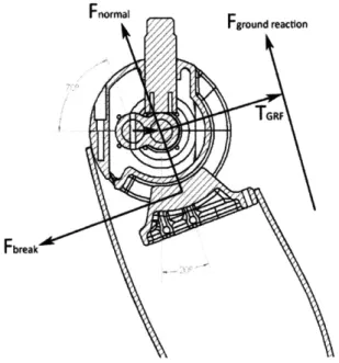
exerted on the knee during loading. Figure 10 is a diagram of the relative forces and torques around the knee axis of rotation during loading. Notice that projection of the normal force
through the shank, Fnor , , reduces the counter-torque of the wedge break. Given the free body
diagram of the knee in Figure 10, a model is later used to analyze the stability of the knee under various loading conditions.
Fnormal
Fground reaction
Fbreak
Figure 10 Force diagram of knee during loading at 20 flexion. Forces and torque around axis
Delrin® was chosen for the first prototype of the Exo-Knee V.3 because of its
machinability and strength, although the final material used for manufacturing will likely have a lower modulus of elasticity. Thermoplastics have been the choice material for JFO for all
prosthetic device hardware because of the cost-effectiveness of injection molding. The 14 individual pieces of the Exo-Knee can be made and assembled for approximately $5 USD.
3.4 Socket Attachment Technique
In order to test the Exo-Knee with patients from JFO, it became necessary to design the
socket interface system to accept a traditional JFO socket. A socket begins as a 4" diameter
section of HDPE pipe which is heated and thermoformed around a positive mold of the residual limb. The distal end of the pipe is typically closed off to increase the stiffness of the socket, but
was left open for integration with the Exo-Knee, as seen in Figure 11. This both decreased the fabrication time of the socket itself, as well as ensured proper fit with the knee for precise
rotational alignment of the lower leg.
Figure 11 Socket interface system; designed to accept a traditional JFO open-ended socket. 23
The addition of ribbing on the outside surface of the socket interface system made for a
more secure fit between the socket and the knee. The open end of the socket would be heated
until soft, pressed around the alignment adapter ensuring a tight fit, and then allowed to cool. The ribs are shown in Figure 12. Once the socket was affixed to the alignment adapter, screws were placed around the circumference of the socket to secure the adapter in the rotational axis.
Figure 12 Ribbing on the socket interface adapter allows for a more secure fit between
the socket and the knee.
The attachment of the alignment adapter allows for rotational adjustment in the sagittal,
coronal, and transverse planes. Currently, there is no translational adjustment in the medial/lateral or anterior/posterior direction possible, but posterior offset of the knee axis for the purpose of shifting the static weight line forward can be achieved by slight hyper-extension of
the knee. Once the knee is in proper alignment for the amputee, a socket clamp is tightened from
the inside of the socket against the alignment adapter to fix its position.
3.5 Shank Integration
Effective integration into current JFO prosthetic infrastructure is paramount, and thus the
knee is confined to integration with an exoskeletal design. JFO uses the same 4" diameter HDPE
pipe used in their socket for fabricating their lower leg shank, pictured in Figure 13, but since tighter manufacturing tolerances can be achieved with the generic shank, the friction break can
be made to fit within the socket snugly and bolted into place. A common problem with the previous Jaipur Knee was that misalignment when drilling holes to bolt the shank brackets to the
shank caused the knee axis to be offset, resulting in an unnatural inversion or eversion of the leg
during swing phase. Using the friction break as a template for drilling holes eliminates this problem and ensures rotation of the main axis stays properly aligned through all phases of gait.
Figure 13 JFO shank designed for the Exo-Knee. Slight modifications were made to this
design, but overall manufacturing methods were preserved.
Currently, all JFO prosthetic devices achieve at least 1350 of flexion for squatting and sitting cross-legged [6]. This is especially important in developing countries because of the predominance of the squat toilet, which requires the user to squat over the ground instead of sit.
Additionally, people generally squat to do work instead of sitting on a bench. To accommodate
for this need, the Exo-Knee was designed to achieve 1350 knee flexion, but falls short at 1120.
This is the maximum angle achievable with the current architecture, but can likely be optimized
should the design prove effective in fulfilling all other functional requirements.
3.6 Foot Selection
Although foot selection is generally independent of the type of knee being used, there is one caveat that is worth considering when choosing which particular foot will promote normal
gait with the Exo-Knee. In stance phase, moments created during heel strike tend to flex the knee joint, effectively promoting instability. This can generally be controlled, but in weaker
patients, it becomes more of a concern. A prosthetic foot that can reduce these moments about
the knee joint will have a better chance of providing effective stance stability; a feature
characteristic of feet with softer heels. By maximizing heel cushioning, the intensity of knee flexion moments is reduced, and the knee is able to achieve foot flat in a controlled fashion.
The Jaipur Foot tends to fall on the stiffer end of the spectrum of heel compliance, and thus may not be the perfect candidate for any trans-femoral knee, whether or not the knee
incorporates stance flexion. In general, a softer heel would be a better choice for the Exo-Knee,
and prototypes currently in the development process are being examined as potential alternatives to a trans-femoral leg system.
4 Modeling the Exo-Knee
In order to determine whether or not it is possible to achieve stance-flexion with the
current Exo-Knee design, a mechanical model is developed for the knee which allowed for static knee torque calculation. This model is presented below, and is referenced by Figure 14, which
depicts the forces on the knee joint in a free body diagram.
S/
/
Figure 14 Free body diagram of the knee model in loading. LI and L2 represent limb lengths, FGRF acts at a distance from the knee center of rotation, creating a flexion moment a distance dGRF away. Conversely, the breaking lever, Rb, creates a locking moment when FGRF is applied through the friction break.
The distance dGRF is calculated by the law of cosines,
dGRF = tan L2 sin(180 - 6)
The ground reaction force FGRF acts a distance dGRF away from the knee axis of rotation,
creating a flexion moment TGRF,
TGRF = dGRF * FGRF
Conversely, the friction break shown in Figure 10 creates a locking moment, TGRF,
which acts to oppose flexion.
tfriction = Ffriction * Rbreak
where,
Ffriction = Mbreak * FGRF * COS 0
When the torque created by the friction break is greater than torque caused by a ground
reaction force, the knee is stable during stance phase. At the instance the ground reaction torque overcomes the breaking torque, a net flexion moment dominates the joint, and the break will slip.
Figure 15 plots knee torque vs. knee flexion angle. Adjusting the knee axis anterior to the
patient's weight reaction line by 10mm creates a negative ground reaction torque (GRT) for the first 20 of flexion. Between 70 and 80 flexion, the net knee torque becomes positive, thus flexing the knee. Based on these data, the model was able to quantify the ability of the Exo-Knee to
14 --- --- ---
-1
-1 0 - - - - - - - - -- -! - ---- | - - - - - - - - -L - - - - - - - - --
-"-"
Ground Reaction Torque
I - I
2knee
to flex, but then overcomes the GRT at 1525o flexion . This would require a net torque
5 Discussion of Findings
-4 - - -- --- ---.. .. .. ...---.-- ---.. - ---FnIn Chapter 4, athe model shfor a stance flexion knee was unlikelopy result forand devan tested to ensuree. Fiaccuracy.e 15 indicates found that the model could not produce athe knee flexed momentis during early support phase. Ing that
Furthermore, any net moment created by the knee is inherently stable during heel strike,
becoming progressively less stable as knee flexion angle increases. This is due to the fact that the friction break creates a near-constant negative torque on the knee at heel strike, which
reduces as knee flexion angle increases. Conversely, the ground reaction torque created during stance increases proportional to the sign of the knee flexion angle.
What is notable in analysis of the mechanical model is that when net knee torque equals
zero, the corresponding flexion angle is independent of the magnitude of the ground reaction force. This is true only when the torque balance is zero, and indicates that the dynamics of knee
loading stability are independent of the user's weight and walking speed. This finding is
promising, as it allows us to design the physical dimensions of the friction break to fit variety of users.
Furthermore, leg segment length variations in the tibia and femur do not affect the torque
balance point as long as the ratio of the upper to lower leg length does not change. This is not necessarily the case from patient to patient, but since it can be assumed that the ratio of leg
segment lengths is relatively constant, patient height can be ignored in a first order approximation of the torque balance point in knee loading.
In order to achieve true stance-flexion, initial knee flexion must create a positive torque
on the knee, promoting flexion. The knee must then apply a breaking torque to fully cancel the knee flexion torque to zero, locking the knee at 15-200 flexion. The graph of net torque vs. knee
flexion angle would thus be positive during the first 150 of knee flexion, and then become
negative, locking the knee at angles greater than 15-20'. This is not achievable with the current design.
A closer look at current stance-flex prosthetic knees on the market reveals a decoupled system for achieving the desired feature, i.e. a combination of an element that achieves stance
flexion with one that locks the knee during stance phase. This allows the knee to flex 15-20',
bottoming out the stance-flexion device as more weight is applied. The stance-lock element engages when any ground reaction force is felt, thus locking the knee during stance and allowing
free rotation during swing. There are currently no devices which aim to achieve stance flexion
with one integrated braking system.
6 Conclusion
Based on these findings, it can be concluded that the device originally conceived as a
stance-flex prosthesis achieves stability through all typical stance-phase knee flexion angles, and
thus functions well as a stance-control device. Weighing the advantages of this device to
previous models of the Jaipur Knee shows a considerable increase in stance-stability and reliability due to the ability of the knee to lock independent of small alignment changes that would otherwise cause the Jaipur Knee to buckle. A user wearing the Exo-Knee will be less
likely to experience a fall from buckling of the knee joint.
The attempt at creating a functional stance-flex knee was not successful with the current model of the Exo-Knee due to the nature of the kinematics inherent in the device. Further work
thus remains to be done to incorporate this feature, and can be approached in a number of
effective ways. The groundwork laid for an exo-skeletal stance-control prosthetic knee was however, ultimately successful, and will later be used as a template for future modifications to achieve true stance-flexion.
7 Acknowledgements
First and foremost, I would like to thank Mr. Sanjeev Kumar for all his help and enthusiasm for every part of this multi-year project. Without his support, my efforts would have had no direction, and with his help, we will be able to bring this device many people in need. I would also like to thank Goutam Reddy and Ken Endo, instructors of the Developing World Prosthetics class. Their teaching and insight on the project was what got me to start working right from the beginning. Additionally, thank you Bob Emerson for your time and effort in this project. It is out of your interest to further our knowledge in the field of prosthetics that you have been able to do so much for us. Lastly, thank you to Professor Hugh Herr, my supervisor and mentor for the writing of this thesis. Your guidance has helped me to understand the intricacies of this project, and your passion for innovation has inspired me to strive for excellence.
8 References
[1] Capital Health. "Levels of Lower Limb Amputations." Capital Health. 28 May, 2007. Copyright © 2005 by Capital Health. 7 May, 2009.
<http://www.cdha.nshealth.ca/default.aspx?page=Expanded¢erContent.Id.0=50 4 4& category.Categories. 1=137>.
[2] Blue Cross Blue Shield. "Medicare Advantage Medical Policy Bulletin." Mountain State Blue Cross Blue Shield. 20 April, 2009. Medicare Advantage. 7 May, 2009.
<https://www.msbcbs.com/medadvpolicy/printerfriendly/O-25-006.html>.
[3] Herr, Hugh. "An Introduction to Human Gait." Developing World Prosthetics. 22 February, 2008. Hugh Herr. 28 April, 2009.
[4] Winter, David A. "Biomechanical Motor Patterns in Normal Walking." Department of Kinesiology, University of Waterloo. 1983. Journal of Motor Behavior. Volume 15, No. 4, 302-330. 3 April, 2009.
[5] Bowker, HK, Michael, JW (editors), "Atlas of Limb Prosthetics: Surgical, Prosthetic, and Rehabilitation Principles." 1992. Rosemont, IL, American Academy of Orthopedic
Surgeons. 15 March, 2009.
[6] Bhagwan Mahaveer Viklang Sahayata Samiti. "Services: Above-Knee Prosthesis." jaipurfoot.org. 2007. Sirez InfoSystems. 3 May, 2009.