Design and Modeling of Membrane-Based Evaporative
Cooling Devices for Thermal Management of High Heat Fluxes
The MIT Faculty has made this article openly available. Please share
how this access benefits you. Your story matters.
Citation Lu, Zhengmao, Todd R. Salamon, Shankar Narayanan, Kevin R.
Bagnall, Daniel F. Hanks, Dion S. Antao, Banafsheh Barabadi, Jay Sircar, Maria E. Simon, and Evelyn N. Wang. “Design and Modeling of Membrane-Based Evaporative Cooling Devices for Thermal Management of High Heat Fluxes.” IEEE Transactions on Components, Packaging and Manufacturing Technology 6, 7 (July 2016): 1056–1065 © 2016 Institute of Electrical and Electronics Engineers (IEEE)
As Published http://dx.doi.org/10.1109/TCPMT.2016.2576998
Publisher Institute of Electrical and Electronics Engineers (IEEE)
Version Author's final manuscript
Citable link http://hdl.handle.net/1721.1/112125
Terms of Use Creative Commons Attribution-Noncommercial-Share Alike
Design and modeling of membrane-based evaporative cooling devices
for thermal management of high heat fluxes
Zhengmao Lu1, Todd R. Salamon2, Shankar Narayanan3, Kevin R. Bagnall1, Daniel F. Hanks1, Dion S. Antao1, Banafsheh Barabadi1, Jay Sircar1, Maria E. Simon2, Evelyn N. Wang1*
1 Massachusetts Institute of Technology, Cambridge, MA 02139
2 Bell Laboratories, Alcatel-Lucent, Murray Hill, NJ 07974
3 Rensselaer Polytechnic Institute, Troy, NY 12180
*Contact author: enwang@mit.edu
Abstract
We present a high-heat-flux cooling device for advanced thermal management of electronics. The device incorporates nanoporous membranes supported on microchannels to enable thin film evaporation. The underlying concept takes advantage of the capillary pressure generated by small pores in the membrane, and minimizes the viscous loss by reducing the membrane thickness. The heat transfer and fluid flow in the device were modeled to determine the effect of different geometric parameters. With the optimization of various parameters, the device can achieve a heat transfer coefficient in excess of 0.05 kW/cm2-K while dissipating a heat flux of 1 kW/cm2. When
applied to power electronics, such as GaN high electron mobility transistors, this membrane-based evaporative cooling device can lower the near junction temperature by more than 40 K compared to contemporary single-phase microchannel coolers.
Introduction
Thermal management has become a critical issue in the semiconductor industry due to the increasing power density of microprocessors, laser diodes and power amplifiers [1-3]. One of the most pressing challenges in current and next-generation electronics is heat removal of wide band gap semiconductors based on gallium nitride (GaN) and silicon carbide (SiC), for high-power radiofrequency (RF) applications [4]. For example, monolithic microwave integrated circuits (MMICs) based on GaN high electron mobility transistor (HEMT) technology are devices of particular importance for microwave applications. With a standard layout [5] (Figure 1(a) and (b)), and a modest power density of 5 W/mm, the heat flux generated over the gate area in the RF MMIC highlighted by the red stripes in Figure 1(a) (0.5 μm × 150 μm each), can be as high as 1000 kW/cm2 [6]. Even on the backside of the die, the heat flux can still be > 1 kW/cm2 [6]. Such high fluxes are likely to induce high temperatures in the gate area, which can reduce the lifetime and the reliability of the GaN HEMT devices [4]. To lower the near junction temperature and handle the high heat loads, new cooling methods are needed.
Many approaches have been pursued, including single-phase forced convection, pool-boiling and flow-boiling. Single-phase cooling has been experimentally demonstrated up to 1.25 kW/cm2 in microchannels [7], but it requires a large temperature difference and high pumping power [8]. Meanwhile, phase change cooling can be more effective, taking advantage of the enthalpy of vaporization and lowering the pumping power requirement. However, phase-change cooling mechanisms, such as pool-boiling, are fundamentally limited by the critical heat flux (CHF), where ~ 400 W/cm2 has been demonstrated [9, 10]. On the other hand, while flow boiling is promising for reducing the pumping power, and achieving a higher HTC and heat flux, flow instabilities [7], temperature and pressure fluctuations [8] are still major concerns.
To address these issues in flow boiling, previous studies have investigated into techniques such as dynamic active flow control [11], integrating microstructures [12], flow re-entrance [13], inlet restriction [14] and phase separation [15-17]. Particularly, in phase separation approaches, liquid is actively pumped into microchannels covered by a hydrophobic nanoporous membrane and vapor is vented through the pores. In these cases, we note that the phase change occurs underneath the membrane, which can create an additional thermal resistance since the transmission probability for vapor molecules to escape the nanopores can be considerably less than 1 [18].
Another approach that makes use of the enthalpy of vaporization and naturally separates the two phases is the implementation of thin film evaporation [19, 20]. In this case, the thermal resistance across the evaporating liquid is minimized by maintaining a thin liquid film across which the overall thermal transport is significantly enhanced. However, active pumping of liquid into the evaporating thin film (< 1 μm thick [21]) over large regions can be impractical due to high pressure drops, requiring significant pumping powers. Consequently, to facilitate passive liquid flow, nano/micro wicks have been utilized to generate capillary pressure to draw liquid into the evaporating thin film region. For example, evaporation from titanium pillar arrays [22] and alumina nanoporous membranes [20, 23] has been studied in previous work.
However, as the characteristic wicking size is made smaller, the capillary pressure and the viscous loss both increase. As a result, in typical microfluidic implementations of thin film evaporation, these two parameters are strongly coupled, limiting the overall performance if the cooling device is not designed appropriately.
To decouple the viscous stress and the capillary pressure, we propose a membrane-based cooling device that leverages evaporation in a thin (thickness < 1 μm) nanoporous membrane (pore diameter ~ 100 nm) supported by microchannels (characteristic dimension < 10 μm), as shown in
Figure 1(c). During operation, the liquid is drawn across the microchannels as it is wicked into the nanopores of the membrane, where it absorbs heat, evaporates into a pure vapor ambient and eventually condenses at a condenser and is circulated back to the inlet of the cooling device (Figure 1(c) and (d)). The heat supplied for evaporation conducts across the substrate to the microchannel walls, then through the membrane to the liquid-vapor interface, where evaporation takes place (Figure 1(c)). The device relies on the capillary pressure supplied by the nanopores to drive the flow, and takes advantage of phase change to dissipate significant amounts of heat. This is done while minimizing the viscous losses for the flow across the microchannels and the membrane, and the overall thermal resistance across the liquid. Consequently, the device can potentially deliver high heat fluxes for cooling, with low overall temperature differences as well as minimal pumping power requirements. The reliance on the capillary pressure within the pores to drive the flow also results in a self-regulating device, which may be able to better address challenges associated with spatially-varying heat fluxes. This is particularly challenging in flow-boiling based approaches, due to pressure instabilities and flow mal-distribution, which is difficult to mitigate at the microscale.
In fact, designing such membrane-base evaporative cooling devices relies heavily on fundamental understanding of interfacial transport at the small scale. In this study, we carried out a detailed computational analysis to design the proposed cooling device, and investigated the overall heat and mass transfer during evaporation, where we carefully account for the sub-continuum and non-equilibrium effects of the vapor transport as opposed to using a constant temperature at the interface [16] or the traditional Schrage’s approach [24]. Using this analysis, we also identified the criteria for the selection of the most appropriate working fluid to deliver the highest performance. We then determined the thermal and hydraulic performance of the cooling device as a function of
different geometric parameters for design optimization. Subsequently, we demonstrated the use of this device for the thermal management of GaN HEMTs [2] (Figure 1(a) and (b)), to show significantly reduced near junction temperatures compared to the baseline performance using a contemporary cooling mechanism.
Baseline Performance using Single Phase Cooling
A common technique to cool GaN HEMTs is to use a single-phase microchannel cooler. For example, Calame et al. demonstrated that die-level heat transfer coefficients (HTCs) of 0.021 kW/cm2-K can be achieved with 1.9 L/min water flowing through copper microchannels [4]. With such microchannel coolers rejecting heat to a reservoir maintained at 25 °C, we simulated the heat conduction in the device to determine temperature and the heat flux distribution in the GaN HEMT (Figure 1(a) and (b)) using the finite element method in COMSOL Multiphysics [25], where the total number of elements was 4383224 and the relative tolerance for convergence was set as 10-6. The thermal conductivities of GaN and SiC (kGaN and kSiC) and the thermal boundary resistance
(RB) between these layers, as a function of temperature, were taken into account as [26]:
1.4 150 (W/m-K) 300 K GaN T k (1) 1.4 420 (W/m-K) 300 K SiC T k (2) 2.76 15 2 1.57 10 (m K/W) 1 K B T R (3)
Using the typical heat fluxes encountered in GaN HEMT (1000 kW/cm2 over the gate area) and
of the die is shown in Figure 1(e), where the peak HEMT device temperature is found to be as high as 218 °C. Additionally, cooling heat fluxes > 1 kW/cm2 are necessary for thermal management
of GaN devices, as shown in Figure 1(f).
Interfacial Transport and Coolant Selection
To properly model the performance of our proposed cooling device, we analyzed transport across the liquid-vapor interface to determine the appropriate boundary condition at the evaporative surface of the cooling device. Traditionally, the interfacial heat transfer coefficient, hin is calculated
using the Schrage equation [24]:
, 1/2 1/2 2 1 2 2 fg eq in Schrage in in h P P h T T R T T
(4)where ̅σ is the accommodation coefficient [27], hfg is the heat of vaporization, R is the specific gas
constant, Peq is the vapor pressure in equilibrium with the liquid, Tin is the temperature at the
interface, and P∞ and T∞ are the pressure and temperature of the vapor in the far field, respectively.
However, it has been shown recently that the traditional approach does not account for momentum and energy conservation [28], which is crucial for the analysis of high flux evaporation.
To predict evaporation more accurately, Labuntsov and Kryukov developed the moment method to solve the Boltzmann transport equation governing the interfacial heat and mass transfer process [29], conserving mass, momentum and energy. In our recent study [18], we utilized this method to analyze evaporation from nanoporous structures. Our investigation of evaporation from nanopores takes into account the non-equilibrium effects and the deviation from classical kinetic theory. In addition, by considering the non-local effects arising from phase-change in nanoporous geometries, and the self-regulation of the shape and position of the liquid-vapor interface in response to
different operating conditions, we quantified the effects of various parameters and determine conditions suitable for evaporation. We found that the interfacial heat transfer is most efficient when the meniscus is pinned at the top of the pore with total accommodation (̅σ = 1 which is more likely for non-polar working fluids [30-33]). For ̅σ = 1, the interfacial transport in nanopores did not depend significantly on the interface shape or the liquid pressure at the interface [34]. Instead, the interfacial HTC hin, normalized over the pore cross-sectional area, varied only as a function of Tin and T∞ as well as the porosity ϕ for pore diameter ~100 nm. We present the analysis for this
particular case (pinning regime with total accommodation) as follows. (Discussion on more general cases can be found in Ref. [18].) For one unit cell, a cylindrical coordinate (r, z) system is defined in Figure 2(a). We set z = 0 at the pore outlet and the far field vapor at z → ∞. We denote
ξ as the velocity distribution function to yield the mass of molecules dm in a unit volume at a
certain velocity u, so that dm = ξ d3u. The distribution of molecules emitted out of the nanopore is
given by the half Maxwellian [18, 29, 35]:
2 0, 0 3/2 2 | exp 2 z in z u in sat RT RT u (5)where ρsat is the saturated vapor density at Tin. Since the evaporation in reality is a dynamic process,
there is also a backflow of vapor molecules whose distribution at z = 0 is assumed to take the form [29]:
2 0, 0 1/2 ˆ)exp
(
2
|
2
z c z u uRT
RT
u
z (6)where ẑ is the unit vector in the z-direction, u∞ is the bulk vapor velocity in the far field and ρc (yet
to be calculated) denotes the effective density of vapor directed back to the pore outlet. The pressure on the top surface of the pore wall Pw can be determined as [18]:
2 3 0, ˆ | p w z r r P
u r d u (7) where r̂ is the unit vector in the r-direction. In the far field (z → ∞), where thermodynamic equilibrium is again realized,
2 3/2 ˆ exp 2 | 2 z u RT RT
u z (8)where ρ∞ is the vapor density in the far field. By conserving mass, momentum and energy (ṁ, Fz
and Ė) between the pore outlet and the far field within the unit cell, we have:
3 3 0 |z z |z z m
u d u
u d u (9)
2 3 3 0 1 | | z w z z z F P
u d u
d u (10) 2 2 3 3 0 | | 2 2 z z z z E
u u d u
u u d u (11)Eqn. (9), (10) and (11) contain three unknowns (u∞, ρc, ρ∞). After non-dimensionalization, we can
represent the solutions as [29]:
1 , in in T u f T RT (12) 2 , c in sat T f T (13)
3 , in sat T f T (14)
where f1, f2 and f3 are all non-negative functions that come from solving Eqn. (9), (10) and (11).
The interfacial heat transfer coefficient out of the pore is then given as:
1 , 3 , in in in sat fg in T T h h RT f f T T (15)
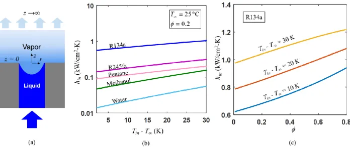
where hfg is the enthalpy of vaporization. This result is plotted in Figure 2(b) for various fluids
(water, methanol, pentane, R245fa and R134a) as a function of superheat (Tin – T∞), assuming T∞
= 25 °C and ϕ = 0.2. We also show the effect of ϕ on hin normalized over the pore cross-sectional
area, for a select working fluid (R134a) with different wall superheats in Figure 2(c).
Following this analysis, the interfacial heat flux is determined exclusively by the temperatures Tin
and T∞, and ϕ for different nanoporous geometries, when divided by the product hfgρsatR1/2. We
evaluate this product at 25 °C and define it as the interfacial heat transfer factor. In order to compare different working fluids, we normalize hfgρsatR1/2 to the value for water and denote this
ratio as:
1
, ,
fg sat
fg water sat water water
h R
h R
(16)
A larger Π1 indicates better interfacial heat transfer, which favors working fluids not only with a
high hfg, but a high ρsat as well. On the other hand, since we rely on the capillary pressure to
overcome the viscous loss, we define the liquid transport factor Π2 as done in heat pipes [36]:
, 2
l fg water water fg water
l water
h h
where σ is the surface tension, ρl is the liquid density and μl is the liquid viscosity. As shown in
Eqn. (17), Π2 was obtained by normalizing with σρlhfg/μ evaluated for water at 25 °C. The rationale
behind using this figure of merit is that the capillary budget scales with σ and the viscous loss scales with μl(ρlhfg)-1 given a heat removal rate. For the same rate of heat removal, a larger Π2
indicates that the device is less prone to dry out. Table 1 shows these two figures of merit (Π1 and
Π2) for select working fluids. Compared to other working fluids, R134a has a much higher Π1.
While Π2 for R134a, R245fa, pentane, and methanol is comparable, it is significantly higher for
water. We chose R134a to carry out device performance analysis, despite its higher risk of dry-out, due to its exceptionally high cooling potential. However, it should be noted that the same computational methodology is indeed applicable for any other working fluid, and can be utilized to determine device performance following a similar procedure. One other concern about R134a
is related to its high saturated vapor pressure (665.8 kPa at 25 °C), which will place the interior of the device at a positive pressure relative to the exterior ambient. We anticipate that such a high operating pressure can be handled by a combination of package-level design coupled with die-level fusion bonding with heat treatment [37].
Table 1 Figures of merit for different working fluids: interfacial transport factor Π1 and liquid transport
factor Π2 (both normalized to the properties of water).
Fluids Water Methanol Pentane R245fa R134a
Π1 1 3.416 6.748 10.56 42.95
Device-Level Model Description
We modeled the pressure drop and heat transfer for the entire cooling device, after choosing R134a as the coolant and determining the pore-averaged evaporative boundary condition hin as a function
of Tin, T∞ and ϕ. The pressure drop in the microchannels is determined as:
2 2 Re l l l h dP f V dx D (18)
where Pl is the pressure in the liquid phase, x is the flow length, Dh is the hydraulic diameter [38], f Re is the Poiseuille number which is depends on the channel aspect ratio (width: depth) AR [39]
and Vl is the bulk liquid velocity in the channel. By mass conservation, we have:
l
ch p
dV
h V x
dx (19)
where hch is the channel height and Vp is the bulk liquid velocity in the pore, which is also
determined by the heat flux being dissipated ̇q″:
(1 ) l fg p
q
h V
SF (20)Here, SF is the channel wall solid fraction tw: (w + tw), where w is the microchannel width and tw
is the channel wall thickness (Figure 1(c)). The pressure drop in the pore is given by:
2 32 l l p p dP V dx d (21)
where dp is the pore diameter. The largest pressure drop in the cooling device is then:
2 2 0 0 2 Re 32 ch l t l l l p h p f P V dx V dx D
d
(22)where lch is the microchannel length and t is the membrane thickness. Assuming that R134a
perfectly wets the pore due to its low surface tension, the capillary pressure is:
4 C p P d (23)
We define a dimensionless pressure budget PB* as the difference between the capillary pressure
and the total pressure drop normalized over the capillary pressure:
* C B C P P P P (24)
For operating conditions with PB* < 0, the cooling device will dry out due to insufficient liquid
supply to the evaporating region.
The heat transfer in the proposed device can be analyzed as a two-dimensional problem, due to the periodic geometry of the cooling device (Figure 1(c)). Figure 3(a) depicts the boundary conditions for a unit cell, marked by the dotted box in Figure 1(c). The governing equation for the steady-state heat conduction across the cooling device is:
(
k T
i) 0
(25)where T is the temperature across the unit cells, i = 1, 2, 3, 4. k1, k2, k3 and k4 denote the thermal
conductivity of the substrate, the channel wall, the porous membrane and the working fluid, respectively. The cooling device was designed in silicon to take advantage of the wide range of microfabrication techniques available for silicon substrates. However, the modeling done in this work can be readily translated to other substrate materials. The temperature dependence of thermal conductivities of silicon and R134a is taken into account as described in Ref. [26] and [40]. The thermal conductivity of the microchannel walls and the nanoporous membrane (k2 and k3) also
depends on the limiting dimension of these structures [41]. Therefore, in this study, the size dependence of k2 andk3 was interpolated from the analyses carried out in Ref. [41].
In Figure 3(a), a uniform heat flux ̇q″ is applied at the bottom of the unit cell, while a pore-averaged evaporative heat transfer coefficient hin is applied on top of the membrane considering the
membrane porosity ϕ. All other boundaries are assumed to be adiabatic and T∞ is set at 25 °C. Note
that a portion of the silicon substrate (1 μm) is also included in the heat transfer model to account for the constriction resistance from the silicon substrate to the channel walls. Eqn. (25) was solved iteratively using finite element method in COMSOL Multiphysics due to the nonlinearity arising from the temperature dependence of ki (i = 1, 2, 3, 4) and hin. The total number of elements in
COMSOL was 13259 in this case and the relative tolerance was set to be 10-6.
Note that heat convection in the liquid phase is neglected in this study. To justify this assumption, we define a modified Péclet number:
2 4 Pe 1 l p p ch c V k SF k SF h
(26)Here, cp is the specific heat capacity of the liquid. The denominator is derived from the combined
thermal conductance of the liquid and the channel wall and the numerator corresponds to the energy carried by the liquid flow in the direction perpendicular to the substrate. This Péclet number compares the heat transfer from the substrate to the membrane due to convection and conduction. As long as Pe ≪ 1, the heat convection in the liquid phase can be neglected. Furthermore, neglecting heat convection only underestimates the device cooling performance, which adds to the safety factor of the proposed design.
Results and Discussion
For the GaN HEMT device shown in Figure 1(a), lch = 700 μm (Figure 1(d)). To calculate the
pressure budget, we first set ̇q″ = 1 kW/cm2, ϕ = 0.25, dp = 100 nm, the membrane thickness t =
300 nm, w = 5 μm, AR = 1, SF = 0.2. PB*was then found to be 0.3423 using Eqn. (18), Eqn. (23)
and Eqn. (24), which indicates that dry-out will not occur for these operating conditions. The temperature profile in the cooling device is plotted in Figure 3(b), which allows evaluation of the overall HTC of the cooling device:
(27)
where Tb is the average temperature at the base of the unit cell (Figure 3 (a)). In this reference case, hd = 0.0441 kW/cm2-K. Also, we verified that Pe = 0.034 with all properties evaluated at 40 °C,
which suggests that convection can be neglected. For comparison with the results obtained for R134a, we also simulated the device performance with water as the working fluid with total accommodation, which gives hd = 0.0155 kW/cm2-K, supporting our rationale for this coolant
selection. Even though water has a very large enthalpy of vaporization, its low vapor density limits the interfacial heat transfer.
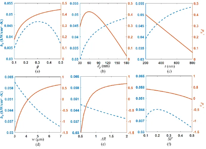
Apart from the reference case study, a parametric sweep of various device geometries was also conducted, where each geometric parameter, namely ϕ, dp, t, w, AR and SF were varied
independently from the reference case described above, and the corresponding effects on the heat transfer and pressure drop are shown in Figure 4(a) – (f).
In Figure 4(a), as the membrane becomes more porous by maintaining a constant pore diameter and increasing the number of pores per unit area, hd first increases due to a larger available
evaporation area. Then, it decreases due to a decrease in the effective thermal conductivity of the membrane. Furthermore, PB* increases with ϕ, since the mass flux in a single pore decreases with
an increase in ϕ.
In Figure 4(b), for all the pore diameters considered, the thermal resistance across the liquid confined within the pore is negligible. However, for a fixed porosity, a larger dp results in a larger
pore spacing, which leads to a higher effective membrane thermal conductivity due to more diffusive thermal transport within the membrane [41]. This results in enhancing the overall heat transfer. On the other hand, since the viscous loss inside the pore scales with 1/dp2 and the capillary
pressure scales with 1/dp, PB*initially increases as dp increases since the decrease in the viscous
loss has a greater effect than the loss in capillary pressure. However, for larger dp, the viscous loss
in the pore is much lower than the loss in the microchannel, and therefore does not affect the total pressure drop significantly. Consequently, a continued decrease in the capillary pressure due to a larger dp causes a decrease in PB*.
Figure 4(c) shows that as the membrane becomes thicker, the spreading resistance within the membrane becomes smaller, which facilitates improvement in the overall heat transfer. However, this effect plateaus as the spreading resistance contributes less to the total thermal resistance while
t increases. PB* decreases rapidly for thicker membranes due to larger viscous losses for flow
through the nanopores.
In Figure 4(d), with increasing channel width, w, the spreading resistance in the membrane increases, which results in performance degradation. Meanwhile, the pressure drop in the microchannels becomes smaller, which enhances PB*. However, PB* becomes insensitive to
A larger AR corresponds to a larger channel height, which results in larger thermal resistance and consequently reduces hd, shown in Figure 4(e). With a decrease in the flux in the microchannels
due to larger flow cross-section area of the channel, PB increases rapidly until the viscous loss
across the membrane dominates.
In Figure 4(f), as SF increases, the membrane area available to wick liquid decreases. Therefore, the flux in a single pore becomes larger, resulting in a larger pressure drop across the membrane, decreasing PB*. An increasing SF also decreases the thermal resistance through the channel wall
and within the membrane, so hd is initially enhanced. However, because the net evaporation area
becomes smaller, hd decreases when SF is relatively large.
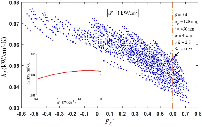
After understanding the effect of each geometric parameter, a global optimization was performed in the design space (containing all of the geometric parameters), evaluating the heat transfer and pressure drop of each design with ̇q″ = 1 kW/cm2 (Figure 5). The criteria for the optimization is
determined based on the application of this technology. For this current study, among parametric combinations satisfying PB* > 0.6, we selected a design which provides the highest hd. With PB* >
0.6, we aim to mitigate the risk of dry-out caused by fabrication uncertainties, such as merging of nanopores and variation of channel sizes, and non-uniform heat fluxes at the backside of the die (up to ~ 2 kW/cm2). The optimum design parameters are given as ϕ = 0.4, d
p = 120 nm, t = 450
nm, w = 4 μm, AR= 2.5, SF = 0.25, which results in hd = 0.0541 kW/cm2-K. Note that this hd was
obtained only for a constant and uniform heat flux (̇q″ = 1 kW/cm2) dissipated by the evaporative cooling mechanism. Due to the temperature dependence of material properties (ki, i = 1, 2, 3, 4)
and interfacial transport (hin), hd also varies as a function of ̇q″ for the chosen geometric design
(inset of Figure 5). Consequently, hd can serve as a non-linear boundary condition when modeling
Evaporative Cooling of GaN HEMT
To demonstrate the feasibility of this proposed device, we model the overall heat transfer by interfacing the GaN HEMT (Figures 1(a) and (b)) with the optimized evaporative cooling device
via gold eutectic bonding. To account for the additional thermal resistance due to the gold eutectic
bond, we included a 10 μm Au and 100 μm silicon layer between the cooling device and the backside of the SiC substrate of the GaN HEMT device. For this configuration, the net heat transfer was again evaluated using the finite element method in COMSOL Multiphysics, where the total number of elements was 4598448 and the relative tolerance for convergence was set as 10-6. The resulting steady state temperature profile across the GaN HEMT device is shown in Figure 6 (a). When compared with Figure 1(e), the benefit of implementation of an evaporative cooling device is clear. While the heat flux distribution at the backside of the die (Figure 6(b)) is similar to the case with microchannel cooler (Figure 1(f)), the near-junction temperature is reduced by 46 K for the chosen GaN HEMT device by implementing the evaporative cooling device.
Although the proposed design shows promise in high flux heat dissipation, its cooling performance largely depends on the accommodation coefficient ̅σ of the liquid-vapor interface and may be subject to non-idealities of the working fluids (e.g., ̅σ is reported to be considerably less than 1 for water in literature [27]). In addition, for practical implementation, non-evaporative contamination in the system can also decrease the effective ̅σ and may eventually clog the device, which is a concern for every evaporation-based system. In our proposed design (Figure 1(d)), there is a constant liquid flow along the channel underneath the pores, which allows the contaminants to diffuse from the liquid-vapor interface back to the bulk fluid and be convected away. The diffusion process is facilitated by the thinness of the membrane, which mitigates the clogging risk.
Conclusions
We propose a membrane-based evaporative cooling device for thermal management of high flux electronics. In order to determine an application-specific design and quantify the overall performance, we carried out a detailed thermal analysis. The analysis incorporates the non-equilibrium effects and the deviation from classical kinetic theory for the interfacial transport. Through the analysis, we identified two non-dimensional quantities, namely the interfacial heat transfer factor and the liquid transport factor, as important criteria for coolant selection. We modeled the overall thermal resistance across the liquid-vapor interface, membrane and the supporting microchannel structure, and the pressure drop associated with coolant supply through the micro/nanofluidic network.
A parametric sweep of critical geometries demonstrates the effect of each parameter on the device performance and a global optimization of device design results in a HTC of 0.0541 kW/cm2-K to dissipate a heat flux of 1 kW/cm2. A non-dimensional analysis also demonstrates that for most state-of-the-art cooling techniques based on micro/nano-wicking structures, there is a qualitative trade-off between thermal performance and risk of dry-out. However, by applying detailed computational analysis and optimization for a particular fluid, one can design a device that meets both performance and reliability metrics successfully over a wide range of operating conditions. The proposed cooling device decouples these two factors by utilizing a thin nanoporous membrane supported on relatively thick and thermally conducting fluidic network. This work can potentially have an impact on thermal management of high flux power electronics, such as GaN HEMTs, by significantly reducing the near junction temperature (by > 40 K) compared to traditional single-phase microchannel cooling, due to a two-fold increase in the die-level heat transfer coefficient.
This work is supported by the DARPA ICECool Fundamentals program with Dr. Avram Bar-Cohen as the program manager. The authors also acknowledge Dr. Rong Xiao at Exxon Mobil Upstream Research Company, Dr. Ryan Enright at Bell Laboratories, Dublin and Prof. Rishi Raj at Indian Institute of Technology Patna for the helpful discussion and suggestions.
Figure 1 (a) Standard lay-out of the reference GaN HEMT described in Ref. [5] (b) Schematic of the cross-section and boundary conditions for GaN HEMT with a silicon microchannel cooler. The temperature dependence is taken into account for thermal conductivities of GaN and SiC and the thermal boundary resistance between them [26]. The inward heat flux and the heat transfer coefficient for silicon microchannel cooler are adapted from Ref. [4] (c) Cross-section and (d) bottom view schematic of proposed cooling device attached to the GaN HEMT die: liquid is routed into microchannels and wicks into nanopores of a membrane supported by channel walls; heat is conducted across the substrate, via the channel walls, within the membrane and to the liquid-vapor interface where evaporation occurs. The evaporated working fluid condenses at a condenser and is then circulated back to the inlet of the cooling device. (e) Temperature profile in the GaN HEMT including both the GaN die and the SiC substrate and (f) heat flux distribution at the backside of the SiC substrate when it is attached to a copper microchannel cooler with a heat transfer coefficient of 0.021 kW/cm2-K [4] rejecting heat to a 25 °C reservoir
Figure 2 (a) Schematic of interfacial transport across a nanopore in a unit cell. (b) Interfacial heat transfer coefficient from nanoporous membrane normalized over pore cross-section area as a function of temperature difference between evaporating surface and far field vapor (T∞ = 25 °C)
with
= 1 and ϕ = 0.2 for different working fluids. (c) Effect of ϕ on hin normalized over poreFigure 3 (a) Boundary conditions for a device unit cell (the yellow dash box in Figure 1(e)): a uniform heat flux ̇q″ is applied to the bottom of the unit cell while an evaporative heat transfer coefficient is assigned on top of the membrane where liquid can wick in. All other boundaries are assumed to be adiabatic. Both the working fluid and the solid material were assigned temperature-dependent thermal conductivities and the thermal transport in the channel wall and the membrane was considered as size-dependent. (b) Temperature profile in the unit cell for a reference design with ϕ = 0.2, dp = 100 nm, t = 300 nm, w = 5 μm, AR = 1 and SF = 0.2
Figure 4 Parametric study of hd (blue dash line) and PB* (orange solid line) as functions of
(a) porosity ϕ, (b) pore diameter dp, (c) membrane thickness t, (d) microchannel width w, (e)
Figure 5 Global optimization of device geometric design at ̇q″ = 1 kW/cm2: to maximize hd
while maintaining PB* > 0.6,the geometric parameters are designed as: ϕ = 0.4, dp = 120 nm, t =
450 nm, w = 4 μm, AR = 2.5 and SF = 0.25. For this optimum design, hd varies as a function of ̇q″
Figure 6 (a) Temperature profile in the GaN HEMT die and (b) heat flux distribution at the backside of the cooler with implementation of the proposed cooling device
Reference
[1] Bartolini, A., Cacciari, M., Tilli, A., and Benini, L., 2013, "Thermal and energy management of high-performance multicores: Distributed and self-calibrating model-predictive controller," Parallel and Distributed Systems, IEEE Transactions on, 24(1), pp. 170-183.
[2] Liou, B.-H., Chen, C.-M., Horng, R.-H., Chiang, Y.-C., and Wuu, D.-S., 2012, "Improvement of thermal management of high-power GaN-based light-emitting diodes," Microelectron. Reliab., 52(5), pp. 861-865.
[3] Pengelly, R. S., Wood, S. M., Milligan, J. W., Sheppard, S. T., and Pribble, W. L., 2012, "A review of GaN on SiC high electron-mobility power transistors and MMICs," Microwave Theory and Techniques, IEEE Transactions on, 60(6), pp. 1764-1783.
[4] Calame, J. P., Myers, R. E., Binari, S. C., Wood, F. N., and Garven, M., 2007, "Experimental investigation of microchannel coolers for the high heat flux thermal management of GaN-on-SiC semiconductor devices," Int. J. Heat Mass Transfer, 50(23-24), pp. 4767-4779.
[5] Garven, M., and Calame, J. P., 2009, "Simulation and optimization of gate temperatures in GaN-on-SiC monolithic microwave integrated circuits," Components and Packaging Technologies, IEEE Transactions on, 32(1), pp. 63-72.
[6] Bagnall, K. R., 2013, "Device-level thermal analysis of GaN-based electronics," Massachusetts Institute of Technology.
[7] Won, Y., Cho, J., Agonafer, D., Asheghi, M., and Goodson, K. E., "Cooling limits for GaN HEMT technology," Proc. Compound Semiconductor Integrated Circuit Symposium (CSICS), 2013 IEEE, IEEE, pp. 1-5.
[8] Prasher, R. S., Chang, J.-Y., Sauciuc, I., Narasimhan, S., Chau, D., Chrysler, G., Myers, A., Prstic, S., and Hu, C., 2005, "Nano and Micro Technology-Based Next-Generation Package-Level Cooling Solutions," Intel Technology Journal, 9(4).
[9] Rahman, M. M., Olceroglu, E., and McCarthy, M., 2014, "Role of Wickability on the Critical Heat Flux of Structured Superhydrophilic Surfaces," Langmuir, 30(37), pp. 11225-11234.
[10] Jaikumar, A., and Kandlikar, S., 2016, "Pool boiling enhancement through bubble induced convective liquid flow in feeder microchannels," Appl. Phys. Lett., 108(4), p. 041604.
[11] Zhang, T., Peles, Y., Wen, J. T., Tong, T., Chang, J.-Y., Prasher, R., and Jensen, M. K., 2010, "Analysis and active control of pressure-drop flow instabilities in boiling microchannel systems," Int. J. Heat Mass Transfer, 53(11), pp. 2347-2360.
[12] Zhu, Y., Antao, D., Bian, D., Zhang, T., and Wang, E., "Reducing instability and enhancing critical heat flux using integrated micropillars in two-phase microchannel heat sinks," Proc. Solid-State Sensors, Actuators and Microsystems (TRANSDUCERS), 2015 Transducers-2015 18th International Conference on, IEEE, pp. 343-346.
[13] Kuo, C.-J., and Peles, Y., 2008, "Flow boiling instabilities in microchannels and means for mitigation by reentrant cavities," J. Heat Transfer, 130(7), p. 072402.
[14] Koşar, A., Kuo, C.-J., and Peles, Y., 2006, "Suppression of boiling flow oscillations in parallel microchannels by inlet restrictors," J. Heat Transfer, 128(3), pp. 251-260.
[15] Agonafer, D. D., Lopez, K., Won, Y., Palko, J., Asheghi, M., Santiago, J. G., and Goodson, K. E., "Phase-separation of wetting fluids using nanoporous alumina membranes and micro-glass capillaries," Proc. Thermal and Thermomechanical Phenomena in Electronic Systems (ITherm), 2014 IEEE Intersociety Conference on, IEEE, pp. 306-316.
[16] Fazeli, A., Bigham, S., and Moghaddam, S., 2016, "Microscale layering of liquid and vapor phases within microstructures for a new generation two-phase heat sink," Int. J. Heat Mass Transfer, 95, pp. 368-378.
[17] David, M. P., Khurana, T., Hidrovo, C., Pruitt, B. L., and Goodson, K. E., "Vapor-venting, micromachined heat exchanger for electronics cooling," Proc. ASME 2007 International Mechanical Engineering Congress and Exposition, American Society of Mechanical Engineers, pp. 951-960.
[18] Lu, Z., Narayanan, S., and Wang, E. N., 2015, "Modeling of Evaporation from Nanopores with Nonequilibrium and Nonlocal Effects," Langmuir, 31(36), pp. 9817-9824.
[19] Narayanan, S., Fedorov, A. G., and Joshi, Y. K., 2013, "Heat and mass transfer during evaporation of thin liquid films confined by nanoporous membranes subjected to air jet impingement," International Journal of Heat and Mass Transfer, 58(1), pp. 300-311.
[20] Xiao, R., Maroo, S. C., and Wang, E. N., 2013, "Negative pressures in nanoporous membranes for thin film evaporation," Appl. Phys. Lett., 102(12), p. 123103.
[21] Wang, H., Garimella, S. V., and Murthy, J. Y., 2007, "Characteristics of an evaporating thin film in a microchannel," International Journal of Heat and Mass Transfer, 50(19), pp. 3933-3942. [22] Ding, C., Soni, G., Bozorgi, P., Piorek, B. D., Meinhart, C. D., and MacDonald, N. C., 2010, "A flat heat pipe architecture based on nanostructured titania," Microelectromechanical Systems, Journal of, 19(4), pp. 878-884.
[23] Narayanan, S., Fedorov, A. G., and Joshi, Y. K., 2009, "Gas-assisted thin-film evaporation from confined spaces for dissipation of high heat fluxes," Nanoscale Microscale Thermophys. Eng., 13(1), pp. 30-53.
[24] Schrage, R. W., 1953, A theoretical study of interphase mass transfer, Columbia University Press.
[25] Pryor, R. W., 2011, Multiphysics Modeling Using COMSOL?: A First Principles Approach, Jones & Bartlett Learning.
[26] Sarua, A., Ji, H., Hilton, K., Wallis, D., Uren, M. J., Martin, T., and Kuball, M., 2007, "Thermal boundary resistance between GaN and substrate in AlGaN/GaN electronic devices," Electron Devices, IEEE Transactions on, 54(12), pp. 3152-3158.
[27] Marek, R., and Straub, J., 2001, "Analysis of the evaporation coefficient and the condensation coefficient of water," Int. J. Heat Mass Transfer, 44(1), pp. 39-53.
[28] Avdeev, A. A., and Zudin, Y. B., 2012, "Kinetic analysis of intensive evaporation (method of reverse balances)," High Temperature, 50(4), pp. 527-535.
[29] Labuntsov, D., and Kryukov, A., 1979, "Analysis of intensive evaporation and condensation," Int. J. Heat Mass Transfer, 22(7), pp. 989-1002.
[30] Wenzel, H., 1969, "On the condensation coefficient of water estimated from heat-transfer measurements during dropwise condensation," International Journal of Heat and Mass Transfer, 12(1), pp. 125-126.
[31] Davis, E. J., Chang, R., and Pethica, B. D., 1975, "Interfacial Temperatures and Evaporation Coefficients with Jet Tensimetry," Industrial & Engineering Chemistry Fundamentals, 14(1), pp. 27-33.
[32] Lednovich, S. L., and Fenn, J. B., 1977, "Absolute evaporation rates for some polar and nonpolar liquids," AIChE Journal, 23(4), pp. 454-459.
[33] Winkler, P., Vrtala, A., Wagner, P., Kulmala, M., Lehtinen, K., and Vesala, T., 2004, "Mass and Thermal Accommodation during Gas-Liquid Condensation of Water," Physical Review Letters, 93(7).
[34] Lu, Z., 2014, "Design and modeling of a high flux cooling device based on thin film evaporation from thin nanoporous membranes," Massachusetts Institute of Technology.
[35] Narayanan, S., Fedorov, A. G., and Joshi, Y. K., 2011, "Interfacial transport of evaporating water confined in nanopores," Langmuir, 27(17), pp. 10666-10676.
[36] Faghri, A., 1995, Heat pipe science and technology, Global Digital Press.
[37] Shimbo, M., Furukawa, K., Fukuda, K., and Tanzawa, K., 1986, "Silicon‐to‐silicon direct bonding method," J. Appl. Phys., 60(8), pp. 2987-2989.
[38] Kundu, P., and Cohen, I., 2008, "Fluid mechanics. 2004," Elsevier Academic Press.
[39] Bahrami, M., Yovanovich, M. M., and Culham, J. R., 2006, "Pressure Drop of Fully-Developed, Laminar Flow in Microchannels of Arbitrary Cross-Section," Journal of Fluids Engineering, 128(5), p. 1036.
[40] Assael, M., Dalaouti, N., Griva, A., and Dymond, J., 1999, "Viscosity and thermal conductivity of halogenated methane and ethane refrigerants," Int. J. Refrig, 22(7), pp. 525-535. [41] Hopkins, P. E., Reinke, C. M., Su, M. F., Olsson, R. H., Shaner, E. A., Leseman, Z. C., Serrano, J. R., Phinney, L. M., and El-Kady, I., 2011, "Reduction in the Thermal Conductivity of Single Crystalline Silicon by Phononic Crystal Patterning," Nano Lett., 11(1), pp. 107-112.
Zhengmao Lu received his B.S. degree in micro-electro-mechanical systems from Tsinghua University, Beijing, China, in 2012, and his M.S. degree in mechanical engineering from the Massachusetts Institute of Technology (MIT), Cambridge, MA, USA, in 2014. He is currently a Ph.D. student at MIT focused on thin film evaporation research. He research interests include phase change phenomena at the micro/nano scale.
Todd R. Salamon is a Member of Technical Staff in the Thermal Management Research Department of Nokia Bell Labs in Murray Hill, NJ. He holds a Ph.D. in chemical engineering from the Massachusetts Institute of Technology, Cambridge, MA, USA. At Bell Labs he has worked on thermal management, microfluidics, transport phenomena in optical fiber manufacturing, design of photonic crystal fibers, and Raman and erbium amplifier dynamics and control in transparent optical networks. He has authored over 40 publications and conference presentations and has 35 issued or pending patents. He was also the Principal Investigator on a U.S. Department of Energy project entitled “Advanced Refrigerant-based Cooling Technologies for the Information and Communications infrastructure (ARCTIC)” to develop and commercialize refrigerant-based cooling technology targeted towards the Information and Communications Technology (ICT) sector.
Shankar Narayanan received his Ph.D. in Mechanical Engineering from the Georgia Institute of Technology, Atlanta, GA, USA, in 2011. He was a post-doctoral researcher at the Massachusetts Institute of Technology, Cambridge, MA, USA, from 2012 to 2015. He is currently an Assistant Professor in the Department of Mechanical, Aerospace and Nuclear Engineering at the Rensselaer Polytechnic Institute, Troy, NY. His current research interests include multiscale transport analysis and fundamental study of phase-change in micro- and nano-structured surfaces for developing environmentally sustainable thermal energy systems.
Kevin R. Bagnall received the B.S. degree in mechanical engineering from the University of Oklahoma, Norman, OK, in 2009 and the M.S. degree in mechanical engineering from the Massachusetts Institute of Technology, Cambridge, MA, USA, in 2013. He is currently pursuing the Ph.D. degree in mechanical engineering at MIT.
In 2009, he was a summer intern with the Sustainability Technology Group, ConocoPhillips, Inc., Bartlesville, OK. Since 2011, he has been a Research Assistant with the Device Research Laboratory, Department of Mechanical Engineering at MIT. His research interests include micro/nano-scale thermal transport, thermal issues in electronics, solid state device physics, and thermal metrology techniques.
Mr. Bagnall is a student member of IEEE and the American Society of Mechanical Engineers (ASME). His honors and awards include the National Defense Science and Engineering Graduate Fellowship and the Rohsenow Mechanical Engineering Graduate Fellowship (MIT).
Daniel F. Hanks received his B.S. in Mechanical Engineering at Duke University, Durham, NC, USA, in 2010 and his M.S. and Ph.D. degrees from the Massachusetts Institute of Technology, Cambridge, MA, USA, in 2012 and 2016, respectively. The focus of his Ph.D. research was experimental validation of high heat flux evaporation from nanoporous membranes for thermal management. He is currently a Mechanical Design Engineer at Tesla Motors
Dion S. Antao received his B.Tech. (Hons.) degree in mechanical engineering from the National Institute of Technology, Jamshedpur, India, in 2007, and his M.S. and Ph.D. degrees in mechanical engineering from Drexel University, Philadelphia, PA, USA, in 2009 and 2013, respectively. He is currently a Postdoctoral Associate in the Device Research Laboratory (DRL) in the Department of Mechanical Engineering, Massachusetts Institute of Technology, Cambridge, MA, USA. At the DRL, his work involves understanding the static and dynamic effects solid-liquid interactions on surfaces with micro/nanoscale structures to enhance
the performance of various energy conversion devices and systems. His current research interests include thermal management of electronic devices, condensation in large-scale power plants, thermoacoustic engine and refrigeration systems, and novel experimental diagnostic methods.
Banafsheh Barabadi received her Ph.D. in Mechanical Engineering from Georgia Institute of Technology, Atlanta, GA, USA, in 2014. She was a post-doctoral researcher in Massachusetts Institute of Technology, Cambridge, MA, USA, from 2014 to 2016 and currently is a research affiliate at the Device Research Laboratory in the Department of Mechanical Engineering at MIT. Her current research involves thermal modeling, characterization, and mitigation of Gallium Nitride based high electron mobility transistors and developing cooling mechanisms for ultra-high heat fluxes.
Jay Sircar graduated from the Massachusetts Institute of Technology, Cambridge, MA, USA, in 2013 with a B.S. in Mechanical Engineering, where he did his undergraduate thesis on improving the manufacturability of welded plate loop-heat pipes. He is currently pursuing his M.S. degree at MIT. His current research focuses on the fabrication and characterization of an intra-chip device for high heat flux cooling utilizing phase change. His
research interests are in thermal fluids, specifically pertaining to energy generation, storage, and usage.
Maria E. Simon received her Ph.D. in Physics from the Instituto Balseiro in Bariloche, Argentina. She was a researcher at Bell Labs (Alcatel-Lucent) working on solid state physics, micro-electro-mechanical systems (MEMS) and nanotechnology. She is currently working on optical networks in the WDM (Wavelength Division Multiplexing) Optics Product Division at Nokia. She has co-authored over 50 publications in journals and conference presentations and has over 30 issued or pending patents.
Evelyn N. Wang is an Associate Professor, the Gail E. Kendall Professor, in the Mechanical Engineering Department at MIT. She is also the Associate Director of the Solid State Solar Thermal Energy Conversion (S3TEC) Center, a DOE Energy Frontiers Research Center and an Associate Director of the MIT Microsystems Technology Laboratories. She received her BS from MIT in 2000 and MS and PhD from Stanford University in 2001, and 2006, respectively. From 2006-2007, she was a postdoctoral researcher at Bell Laboratories, Alcatel-Lucent. Her research interests include fundamental studies of micro/nanoscale heat and mass transport and the development of efficient thermal management, water desalination, and solar thermal energy
systems. Her work has been honored with awards including the 2012 ASME Bergles-Rohsenow Young Investigator Award in Heat Transfer, as well as several best paper awards. She is an ASME fellow.

![Figure 1 (a) Standard lay-out of the reference GaN HEMT described in Ref. [5] (b) Schematic of the cross-section and boundary conditions for GaN HEMT with a silicon microchannel cooler](https://thumb-eu.123doks.com/thumbv2/123doknet/14680853.559220/21.918.111.807.115.421/figure-standard-reference-described-schematic-boundary-conditions-microchannel.webp)