Action Selection and Vertical Plane
Dynamic Control for Survey-Class
Autonomous Underwater Vehicles
byChristopher Michael Smith
S.B., Massachusetts Institute of Technology (1991) Submitted to the Department of Ocean Engineering in partial fulfillment of the requirements for the degree of
Master of Science in Ocean Engineering at the
MASSACHUSETTS INSTITUTE OF TECHNOLOGY September 1994
®Massachusetts Institute of Technology 1994. All rights reserved.
Author
...-...
Author
...
...-
...
Department of Ocean Engineering...
.
;" .
1
A
S
u gust
9, 1994
Certified
by
----
....
-...
.-
...
Michael S. Triantafyllou Professor of Ocean Engineering Thesis Supervisor Accepted by.
A
ccepted
by
... .'' . ...- ... ...
A.ouglas Carmichael
Chairman, Departmental Committee on Graduate Students
J W ItHD;R^ WN j
Action Selection and Vertical Plane
Dynamic Control for Survey-Class
Autonomous Underwater Vehicles
by
Christopher Michael Smith
Submitted to the Department of Ocean Engineering on August 9, 1994, in partial fulfillment of the
requirements for the degree of Master of Science in Ocean Engineering
Abstract
As autonomous underwater vehicles (AUVs) expand their role in oceano-graphic research, the complexity of their expected missions and behavior sets also increases. This trend requires an approach to structuring AUV con-trol which can provide reliable, rational, and time-sensitive trade-offs between relatively abstract criteria such as power conservation, robustness to environ-mental variations, and exploitation of serendipitous opportunities. Concepts from action selection and systems and control theories are integrated in an asynchronous action hierarchy to meet these challanges. A general transit dynamic controller is developed both to illustrate the use of the asynchronous action hierarchy concepts and to highlight the advantages to integrating the projects of action selection and dynamic control. The performance of the general transit controller and the asynchronous action hierarchy is evaluated and future areas of research are identified.
Thesis Supervisor: Michael S. Triantafyllou Title: Professor of Ocean Engineering
Acknowledgements
There are of course many people without whom this thesis would have been impossible. I would especially like to thank the MIT Sea Grant College Pro-gram and its director, Dr. Chrys Chryssostomidis, for providing a research environment that I found both excellent and challanging. I would also like to extend my sincere thanks to Dr. Michael Triantafyllou, my thesis advisor, for all of his help and for teaching me to really enjoy ocean engineering. The research staff of the Underwater Vehicles Laboratory has helped with un-countable problems. I would like to extend thanks to Jim Bellingham, Tom Consi, Jim Bales, John Leonard, Don Atwood, Cliff Gaudy, Drew Bennett, and Brad Moran for all of their help and support. Many thanks also to Mike Drooker and the MIT Ocean Engineering Design Lab for excellent worksta-tions with little downtime. Finally, I would like to thank Stoy for putting up with me through all this.
This research was funded under the following grants: Office of Naval Re-search grants N000-14-91-J-1014 and N000-14-92-J-1287, and Sea Grant/NOAA grant NA-90-AA-D-SG424.
DEDICATION
I have learned
To look on nature, not as in the hour
Of thoughtless youth; but hearing oftentimes The still, sad music of humanity,
Nor harsh not grating, though of ample power To chasten and subdue. And I have felt
A presence that disturbs me with the joy Of elevated thoughts; a sense sublime Of something far more deeply interfused, Whose dwelling is the light of setting suns, And the round ocean and the living air, And the blue sky, and in the mind of man.
-Wordsworth from 'Lines composed a few miles above Tintern Abbey'
To my Mother and Father
1 Introduction
2 Action Selection
2.1 The Action Selection Problem ...
2.1.1 Current Structure of Odyssey Intelligence ... 2.1.2 Generalized AUV Intelligence Architecture ... 2.1.3 Impact on Vehicle Control ...
2.2 Approaches to Action Selection ... 2.2.1 Behavior-based decomposition. 2.2.2 Emergent complexity .
2.2.3 Situated instruction use and deictic representation . 2.2.4 Ethologically-inspired action hierarchies
2.2.5 Recommendations . ... 2.3 Asynchronous Action Hierarchies ...
2.3.1 Structure of the Action Hierarchy .... 2.3.2 Example Operation of the Asynchronous
erarchy .
2.3.3 Requirements for Vehicle Control .... 3 Vehicle Modeling
3.1 Physical Description of the Vehicle Platform 3.2 Vehicle Dynamics ...
3.2.1 Hydrostatic Forces. 3.2.2 Inertial Forces .
3.2.3 Viscous Forces . ... 3.2.4 Thruster Model.
3.3 Summary of Vertical Plane Dynamics ...
Activity Hi-17 19 20 20 20 23 23 24 24 26 27 27 28 30 31 35 36
... . 37
... .. 41
... .. 41
... . 42
... . 46
... . 48
... . 53
5Contents
CONTENTS 6
3.3.1 Steady State Dynamics ... 53
4 Controller Development 61 4.1 Basic Actions ... 62
4.1.1 Gliding . . . ... 63
4.1.2 Transitioning Between Glides ... . 63
4.1.3 Depth Changes ... . 64
4.2 Controller Structure ... . 65
4.2.1 Command Modes ... .. 68
4.2.2 Controller Parameters . . . ... 68
4.3 Performance Metrics ... 69
4.4 Choosing the Transition Decay Time Constant . ... 71
5 Controller Performance 74 5.1 Controller Performance ... 74
5.1.1 Estimating the Recovery Draft . . . .... 79
5.2 Angular Resolution ... . 83 5.3 Controller Sensitivity . ... . 86 5.3.1 Parametric Errors ... 87 5.3.2 Measurement Noise .. . . . 88 5.3.3 Process Noise . . . ... 88 5.4 Conclusions ... ... 90
6 Future Research Directions 94 6.1 Vehicle Modeling ... 94
6.1.1 Refining the Vehicle Dynamic Model ... 94
6.1.2 Adaptive Modeling ... 95
6.2 The Asynchronous Action Hierarchy ... 95
6.2.1 Utilizing Endogenous Variables . ... 95
6.2.2 Expanding the Action Repertoire . ... 95
6.2.3 Adding Dynamic Controllers . ... 96
6.3 Other Research Areas . . . ... 96
6.3.1 Combining Model Information . ... 96
List of Figures
2.1 The current intelligence architecture of the AUV Odyssey . 21
2.2 A more generalized intelligence architecture ... 22
2.3 The behavior-based approach to action selection . ... 25
2.4 Information flow in the general agent architecture ... . 29
2.5 An example of the asynchronous action hierarchy ... 33
3.1 General configuration of an Odyssey vehicle . . . ... 38
3.2 An Odyssey fin, as modeled . ... 39
3.3 Variables used in the vertical plane vehicle model ... 40
3.4 Vehicle cross-section with fins . ... ... 46
3.5 Thruster motor model ... 49
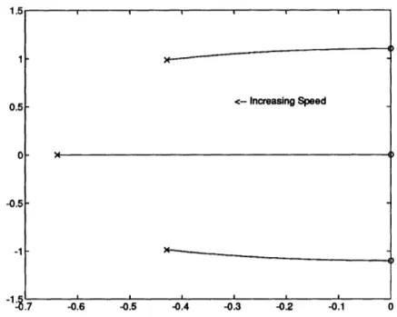
3.6 Vehicle natural frequencies for perturbations around a steady dive as a function of steady surge velocity u. 60 = 0 ... 56
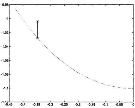
3.7 Vehicle natural frequencies as a function of elevator angle. . . 57
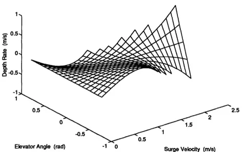
3.8 The dependance of steady dive rate on steady forward velocity and elevator angle. ... 58
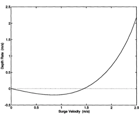
3.9 The dependance of steady-state depth rate on vehicle steady forward velocity. 5& is set at 20 degrees . ... 59
4.1 A step change in commanded elevator angle excites unwanted dynamics ... 64
4.2 The general transit dynamic controller situated in the asyn-chronous action hierarchy. ... . 66
4.3 Finite state representation of the general transit dynamic con-troller ... 67
4.4 Example of the performance metrics used to evaluate the gen-eral transit dynamic controller. ... 70 4.5 Maximum pitch overshoot versus transition decay time constant. 72
LIST OF FIGURES
4.6 Maximum settling time versus transition decay time constant. 73 5.1 General transit controller settling time performance ... 75 5.2 General transit controller depth overshoot performance. .... 76 5.3 General transit controller depth undershoot performance .... 77 5.4 General transit controller pitch overshoot performance. .... 77 5.5 Controller performance during slow speed transitions ... 78 5.6 Controller performance during medium speed transitions .... 80 5.7 Controller performance during high speed transitions ... 81 5.8 Estimated recovery draft as a function of vehicle surge velocity
and elevator angle. ... 82
5.9 Recovery draft estimate error. . . . ... 83
5.10 Slow speed performance with angular resolution effects .... 84 5.11 Medium speed performance with angular resolution effects. .. 85 5.12 High speed performance with angular resolution effects .... 86 5.13 Errors and noises in modeling . ... 87 5.14 Controller performance with added process noise at slow speed. 89 5.15 Controller performance with added process noise at medium
speed ... 91 5.16 Controller performance with added process noise at high speed. 92 8
List of Tables
3.1 Thruster Model Parameters ... ... 53 3.2 Vehicle Hydrodynamic Derivatives ... 54 5.1 General Transit Dynamic Controller Performance ... 79
List of Symbols
A system state matrix
A fin aspect ratio
A thruster cross-sectional area
a hull radius
a aspect ratio constant
OaCr Oa fin marginal lift coefficient
D vehicle diameter
Fi generalized force
g gravitational acceleration I.. moment of inertia along x axis
Iyy moment of inertia along y axis
IZ moment of inertia along z axis i thruster current
i index
j
index
K general roll moment
Ifin thruster entering fluid specific kinetic energy
LIST OF SYMBOLS
Ifout
KT k L 1thruster exiting fluid specific kinetic energy
thruster electrorotational gyrator conversion constant index
vehicle length index
M body mass tensor
M general pitch moment
Madded mass pitch moment due to added mass
Mbody mass pitch moment due to body mass
Mfin lift pitch moment due to fin lift
Mhul lift pitch moment due to hull lift
Mhydrostatic pitch moment due to hydrostatic forces
Mi generalized moment
Mnom nominal force upon which pitch process noise is based
Mq pitch velocity pitch hydrodynamic coefficient
Mq pitch acceleration pitch hydrodynamic coefficient
MA surge acceleration pitch hydrodynamic coefficient
M,. heave velocity pitch hydrodynamic coefficient
MI heave acceleration pitch hydrodynamic coefficient
Msection pitch moment on a cross-section
Mslender body slender body approximation of pitch moment
M6 fin angle pitch hydrodynamic coefficient
LIST OF SYMBOLS
Me pitch angle pitch hydrodynamic coefficient
m vehicle mass ma added mass tensor
circle added mass coefficient for a circular cross-section added mass coefficient for a circular cross-section with cruciform fins
mij generalized mass coefficient
N general yaw moment p roll angular velocity
Q thruster volumetric flowrate q pitch angular velocity
perturbed pitch velocity
RE thruster electrical resistance r yaw angular velocity
S fin projected surface area
s fin span
s maximum radius of a circular cross-section with cruci-form fins
UT thruster thrust
T thruster fluid total kinetic energy
t time
ts settling time
to time at which a transition begins
ma
macircle with
LIST OF SYMBOLS
Ui generalized velocity
u surge velocity
iU expected surge velocity
Uno dive the critical velocity at which the steady state depth rate
is zero
Uout thruster exit velocity
uss steady-state surge velocity
V total velocity in the vertical plane V thruster input voltage
v sway velocity
w heave velocity
fw expected heave velocity wrC, perturbed heave velocity
Wsection heave velocity at a cross-section
Wss steady-state heave velocity X general axial force
Xadded mass surge force due to added mass Xbody mass surge force due to body mass
Xdrag surge force due to drag
Xnom nominal force upon which surge process noise is based
X4 pitch acceleration surge hydrodynamic coefficient XU surge velocity surge hydrodynamic coefficient Xi, surge acceleration surge hydrodynamic coefficient
LIST OF SYMBOLS
Xfin lift Xhull Xhull lift Xsection Y y Z Zadded mass Zbody mass Zf in lift Zhull lift Znom Zsection Zslender body Zq Zq Zu Z6 Zaxial direction in vehicle-fixed coordinates axial position of the fin lift force
axial position of a cross-section, restricted to the do-main over which the hull is defined
axial position of the hull lift force axial position of a cross-section general lateral force
lateral direction in vehicle-fixed coordinates general vertical force
heave force due to added mass heave force due to body mass heave force due to fin lift heave force due to hull lift
nominal force upon which heave process noise is based heave force on a cross-section
slender body approximation of heave force pitch velocity heave hydrodynamic coefficient pitch acceleration heave hydrodynamic coefficient heave velocity heave hydrodynamic coefficient heave acceleration heave hydrodynamic coefficient fin angle heave hydrodynamic coefficient
vertical direction in vehicle-fixed coordinates
LIST OF SYMBOLS
ZG distance between the centers of buoyancy and gravity
in the z direction
ac sideslip angle in the vertical plane 1l surge added mass coefficient parameter V effective thruster volume
6 elevator angle
bcommand commanded elevator angle
f target elevator angle
,0 constant or initial elevator angle e Kronecker delta
vertical direction in earth-fixed coordinates
Cover depth overshoot
Crd recovery draft
(under depth undershoot
r7 lateral direction in earth-fixed coordinates 7rp effective propeller pitch
0 pitch angle
Oover pitch overshoot 9 perturbed pitch angle 09S steady-state pitch angle
# dive angle coefficient v process noise variable
horizontal direction in earth-fixed coordinates
LIST OF SYMBOLS 16 p water density
0f sideslip ratio
Onoise process noise standard deviation
T propeller torque
Tdecay transition decay time constant
TSF propeller static friction
Pi generalized angular velocity
Chapter 1
Introduction
Autonomous underwater vehicles (AUVs) hold great promise for enhancing oceanographic research. Their perceived role is increasing from a solution to the exploration of otherwise inaccessable regions, such as beneath the polar ice caps, to one of cooperative engagement with other forms of ocean moni-toring, such as remotely operated vehicles (ROVs) and manned submersibles. As the role of AUVs in oceanographic research increases, they are required to exhibit ever more complex sets of behaviors and goals. A higher level of competance is demanded both in terms of autonomous decision-making and judgements about the vehicle's situation and environment and in terms of reliability of individual subsystems and the vehicle as a whole. This trend requires an approach to structuring AUV control which can provide reli-able, rational, and time-sensitive trade-offs between relatively abstract crite-ria such as power conservation, robustness to environmental vacrite-riations, and exploitation of serendipitous opportunities. The objective of this thesis is to adapt the current structure of vehicle intelligence in order to provide such a unifying mechanism for vehicle action selection and control in the presence of widely varying goals, behaviors, and environments.
We begin with a consideration of the action selection problem in Chap-ter 2. Because of the wide range of behavior modules used in a complex autonomous agent such as an AUV, a single dynamic controller, such as the product of system and control theoretic considerations, will fail to address the varying control needs of different behaviors. Conversely, higher level studies of action selection have tended to focus at a level of abstration much more complex than vehicle dynamics, complicating the implementation of
CHAPTER 1. INTRODUCTION
these ideas on a mobile robotic platform with non-trivial dynamics. Con-sideration of the contributions of both fields leads to the development of an asynchronous action hierarchy to manage vehicle action selection, activity implementation, and dynamic control for the AUV. The next three chapters cover the development of a dynamic controller for general transit and illus-trate the interleaving of concerns relating to action selection and dynamic control. The particular project of general transit dynamic control serves to highlight both the impact of dynamic control on action selection and the power of action selection theory in helping to formulate control strategies. A model of the vertical plane dynamics for a survey-class AUV is derived in Chapter 3. The importance of various forces in determining control at-tributes such as natural frequency and steady-state response is noted. The development of the general transit vertical plane dynamic controller is begun in Chapter 4. This controller is designed to demonstrate the construction of a vehicle dynamic controller using activity modules; traditional control theoretic priciples give way to a more ethologically-inspired approach of ac-tion selecac-tion under condiac-tions of general transit. The operating regimes for this controller are discussed along with its integration with other dynamic controllers in the asynchronous action hierarchy. The performance of the general transit controller is evaluated in Chapter 5. The performance of the controller in simulation is presented, and the sensitivity of the general transit controller to various types of modeling errors is also examined. In Chapter 6, conclusions about the action hierarchy approach to action se-lection and dynamic control are drawn. Future research possibilities, such as specific implementation issues for the hierarchy and the general transit controller, are discussed.
Chapter 2
The Problem of Action
Selection
Perhaps the most central question for an autonomous agent such as an AUV is what to do next. The artificial intelligence literature refers to this as the action selection problem and has produced a number of approaches to its solution. Action selection approaches in behavior-based artificial intelligence accentuate the need for adaptivity and use of emerging opportunities to meet multiple, possibly conflicting goals. Literature on dynamic control, on the other hand, only implicitly asks the question. Control theory is concerned precisely with the question of what motor actions should be carried out. A control theoretic approach often involves determining the in some sense optimal general solution for mapping the current and desired vehicle states into an actuator command. When a system becomes more complex, the specific needs that the controller tries to meet may change drastically, in which case the action selection approach is necessary. But dynamic control is an ever present requirement, so the issue of vehicle dynamics cannot be ignored. In this chapter, the role of action selection for an AUV is examined and the impact of action selection on control strategies is addressed. This leads to the development of an action selection model for use in a survey-class AUV. Its relationship to other action selection approaches is described and its impact on vehicle control is identified.
CHAPTER 2. ACTION SELECTION
2.1 The Action Selection Problem
2.1.1
Current Structure of Odyssey Intelligence
Before considering the action selection problem further, it is useful to take a look at the current intelligence architecture, shown in Figure 2.1. Intelligence architecture refers to the structure of the decision-making modules which make up the vehicle's programming. The level of resolution of an intelligence architecture is more abstract than a specific software implementation, but captures to flow of information, control, and decision-making capabilities. The goals of the vehicle are embodied in a set of behavior modules. These modules synchronously produce suggested actions for the AUV based on the current vehicle state and their particular projects. The behavior modules and their associated suggested actions have a priority which is determined as part of the mission setup. A fixed arbitration scheme is used to select the appropriate (highest priority) action for the AUV to pursue. A dynamic controller transforms this desired action into actuator commands.
The current approach to structuring AUV intelligence have yielded good overall performance. Experience has indicated, however, that an improved approach to action selection will further streamline the process of combining the wide variety of behaviors necessary for reliable operation in an unknown and rich dynamic environment. While any particular control strategy might be suitable under certain circumstances, control theory does not extend to the dynamic breadth required of the vehicle under all circumstances. Ad-ditionally, the fixed arbitration scheme hampers vehicle adaptivity in the presence of changing goals. For these reasons, casting the control problem as a part of action selection makes sense.
2.1.2
Generalized AUV Intelligence Architecture
The combined problems of action selection and dynamic control are tack-led by providing an organized structure between the behavior modules and the motor and sensory subsystems, as shown in Figure 2.2. This structure contains the mechanism for combining the suggested actions of the various behaviors (at various levels of abstraction) and processing them using the ap-propriate dynamic control strategy to produce commands at the level of the motor and sensory subsystems. Furthermore, we explicitly acknowledge the
CHAPTER 2. ACTION SELECTION
l
I L
l
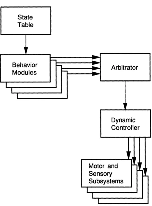
Figure 2.1: The current intelligence architecture of the AUV Odyssey. A state table configures the set of operative behavior modules. The arbitrator selects the highest priority requested action for implementation through the dynamic controller. State Table Behavior Modules Arbitrator I~~~~~ Dynamic Controller Motor and Sensory Subsystems I ! . l
-I
I I I . l _ - --~~~~~~~~~~I 11 I I I -21 ICHAPTER 2. ACTION SELECTION
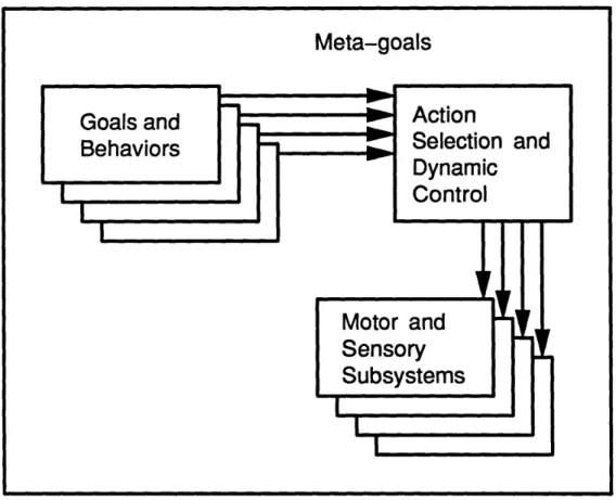
Figure 2.2: Action selection and dynamic control in a more generalized AUV intelligence architecture. An integrated structure handles action selection and dynamic control for the agent. The cotext of the actions is encoded in meta-goals.
fact that action selection and dynamic control take place in the larger con-text of a vehicle mission. This concon-text is represented by meta-goals, adaptive vehicle attributes which reflect a disposition or tendancy in the way actions are implemented. These meta-goals facilitate the determination of the proper control trade-offs, such as between power conservation and trajectory accu-racy, by the action selection and dynamic control mechanism. By providing a structured way of communicating intentions among behaviors, activities, and controllers, the meta-goal paradigm aids in maintaining modularity in the intelligence architecture.
Goals and
Behaviors
Action
Selection and DynamicControl
Meta-goals
I I'I
If I I _-4 _ _
I
Sensory
Subsystems
22 U_r
-! __W_ I I - l _ i -I I 1 [ R A ... .. r r% ,% Ir.
I IVIULUI C IU [! Iir I II I I!i rL] I I I I I ICHAPTER 2. ACTION SELECTION
2.1.3
Impact on Vehicle Control
The restructuring of the intelligence architecture to address the action selec-tion problem amounts to a change in attitude about dynamic control from the control theoretic approach. We recognize that dynamic control solutions are not general. In fact, the real-time selection of and switching between controllers opens the possibility of developing niche controllers for particular situations. A dynamic controller is not monolithic; its control extends to the instantiation of a particular action in the context of the meta-goals. These changes place certain requirements upon controllers for them to be effectively used in this intelligence architecture. The controller must be able to handle asynchronous operation, being switched on and off, possibly often. Also, the controller should be able to incoporate the information from the meta-goals. The control parameters should be adaptive to the context of the action be-ing performed. It should be noted that individual dynamic controllers can be developed using control theory, and in fact, existing controllers may be used. The only alterations necessary are
1. the addition of hooks for using the meta-goals to determine control parameters where appropriate, and
2. the provision to the action selection mechanism of some knowledge about the controller's performance to ensure suitable arbitration.
2.2 Approaches to Action Selection
Action selection has become one of the major research questions in behavior-based artificial intelligence. There are several good surveys of research on the problem. Georgeff [13] and Chapman [8] are good overviews of the traditional approach to planning and how it bears on action selection. Although their domain-independant stance has proven less useful for mobile robots, these papers provide a good grounding of behavior-based action selection research in more traditional artificial intelligence planning. Tyrrell [29] and Maes [23] survey the major projects which have resulted from behavior-based action selection research. They also provide a useful set of criticisms of existing implementations of solutions to the action selection problem. We will now look at several seminal ideas that have emerged in the literature and consider how they bear upon the current project.
CHAPTER 2. ACTION SELECTION
2.2.1 Behavior-based decomposition
In the traditional approach to AI (as opposed to behavior based artificial intelligence) the project of general intelligence is decomposed by function rather than task. In such a system, action selection is performed by a general planner which is distinct from a general dynamic controller. Part of the drawback of such an approach has been addressed already as the difficulty in producing a general dynamic controller. The required dynamic range of such a controller for a complex agent is simply too broad for most control strategies to have any chance of producing an acceptable solution. There is, however, an even greater problem. When an agent's activities are functionally decomposed, there is a computational bottleneck in perception and planning. Instead of each behavior paying attention to the sensory data which pertain to it, the agent processes all of its sensory data at once. The solution to this bottleneck came with a behavior-based decomposition of the agent's software, as shown in Figure 2.3. This approach to decomposing the agent software is based on various tasks or behaviors. Behaviors that take little time and computational resources are run in parallel with slower, and necessarily more long-range, modules. In this way, the agent can maintain continuous control and respond to its environment in real time.
2.2.2
Emergent complexity
Braitenberg [5] argues that much of the behavior that is thought of as very complex or intelligent can be produced by simple feedback from the environ-ment. Brooks [6] couples this idea with inspiration from insect systems and uses a behavior-based approach to emphasize the importance of low-level con-cerns in making an agent work. More complex behaviors are demonstrated as emerging from simple, low-level, reflex-like systems. Simple interactions between an agent and the environment can engender what is objectively in-terpreted as intelligent behavior. This idea has two important consequences. First, behavioral complexity needn't be a result of a complex agent archi-tecture. It could, rather, be the result of the interplay between a simple control law and a complex environment. Behaviors which appear to require a great deal of complexity or computation may have solutions which exploit simple geometrical or feedback interactions with the environment. Wehner [31] illustrates this with a variety of examples in animal behavior. Second,
Sensors Sensors -C -0 0 a= . j a C X & E 0..~~
~~
0 Traditional Decompositionreason about objects plan changes to the world
identify objects monitor changes build maps explore wander avoid objects 25 -- Actuators - Actuators Behavior-Based Decomposition
Figure 2.3: The behavior-based approach to action selection. While tra-ditional artificial intelligence divides the activity of the agent according to function, behavior-based artificial intelligence decomposes agent intelligence
by task, preventing bottlenecks in sensory processing. (after Brooks [6]) CHAPTER 2. ACTION SELECTION
CHAPTER 2. ACTION SELECTION
and relatedly, a given behavioral response will acquire additional complexity when coupled with a rich dynamic environment. This complicates any global analysis of the resulting vehicle behavior.
2.2.3 Situated instruction use and deictic
representa-tion
Agre and Chapman [1] provide two very useful concepts for action selection and control: situated instruction use and deictic representation theory. The idea behind situated instruction use is that an agent knows quite a bit about what it is doing. Any instructions sent to the agent in real time can capitalize on the agent's knowledge of the situation. This idea plays itself out in human interactions all the time. For example, when two people are riding in a car and the passenger says 'Turn left,' the driver knows to wait until the next street before turning. By assuming a common base of knowledge between two behaviors or agents, the amount of communication required to deliver a given instruction can be greatly reduced.
Many traditional planners use a semantic representation of objects. A specific obect is identified by its type and the instance of that type that it represents. A mobile robot might move from room 3 to room 4, for ex-ample. This follows the traditional AI tendancy to separate symbolic un-derstanding as a function. An approach more in line with behavior-based AI relies less heavily on typing objects. Deictic representation theory, also called indexical-functional representation, considers objects as they relate to the agent. Although the agent may use types to describe the objects, the relationship between the agent and the object is seen as more important. For example, the robot moves from the-room-I-am-in to the-room-I-want-to-be-in. Agre and Chapman [1] argue that a deictic representation of the agent's environment is more useful for action selection as response time be-comes more critical. By focusing on the relationship between the object and the agent, deictic representation simplifies the decisions that the agent must make and concommitantly focuses the agent on those things most relevant to it.
CHAPTER 2. ACTION SELECTION
2.2.4
Ethologically-inspired action hierarchies
The action hierarchy model of action selection has been inspired by a devel-oped body of ethological research. Studies of animal behavior have led to (primarily) this type of description for animal behavioral systems. The work of Tinbergen [28], Lorenz [21], and Gould [16] has provided a rich starting point for the design of artificial action selection mechanisms. There are a variety of ethological models of action selection, but the essential features are as follows. Animal behavior is organized into behavioral systems, such as food-gathering, mating, and migration. Each system is a hierarchy of possi-ble actions, composed at the finest grain of organized motor programs and fixed action patterns. These units are combined into instincts and behaviors. Activation for given behaviors comes about through the interplay of releas-ing mechanisms and endogenous factors. Releasreleas-ing mechanisms are external stimuli which allow behavior to proceed in a certain direction. Endogenous factors include hormones, proprioceptive sensations, and motivational im-pulses from other parts of the action hierarchy. Maes [22] incorporates these ideas basically as they are presented by Tinbergen. Blumberg [4] extends this implementation with insight into the action selection project provided by Tyrrell [29].
2.2.5
Recommendations
The intelligence architectures of Brooks [6], [7] and Maes [22] are strictly winner-take-all. The agent decides which behavior will be given control and no attempt is made to incorporate the needs of other behaviors. The prob-lem with such a approach, as pointed out by Tyrrell [29], is that the optimal action may be abandoned by considering only what the winning action re-quires. Blumberg's [4] implementation of an action hierarchy helps solve this problem. The final action is provided with recommendations from those ac-tions which lost at each level in the hierarchy. This is a compromise between the combonitorial explosion occasioned by a full action-space search and the missed opportunities of a strictly winner-take-all contest. However, Blum-berg doesn't have much to say about implementing recommendations, and in fact his examples extend only to the level of behavioral systems, trading off searching for food versus bathing, for example. This assumes a great deal of shared knowledge among the actions both across each level of the
CHAPTER 2. ACTION SELECTION
archy and between levels, as a low-level action may try to incorporate the recommendation of a higher-level action.
2.3 Asynchronous Action Hierarchies
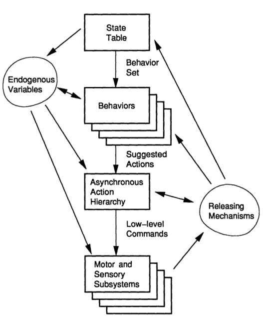
The question posed at the beginning of this chapter was what form of action selection and dynamic control mechanism should be incorporated to medi-ate between vehicle behavioral modules and the actuation and perception subsystems. The following asynchronous action hierarchy incorporates the principles of action selection discussed while avoiding the problems which commonly exist in agent action selection architectures. Before we consider the detailed structure of the action hierarchy, it will be informative to re-visit the general AUV agent architecture picture in light of the discussion of action selection. Figure 2.4 illustrates the agent architecture and indicates the flow of information of various types. The state configuration table sets the goals of the AUV for a particular mission phase by activating an appro-priate set of behavior modules and their priorities. These behavior modules, in turn, provide suggested vehicle activities according to the vehicle's sit-uation and the goals they represent. This is in line with the architecture currently in use. The action hierarchy arbitrates among suggested activities, incorporating information about the internal state of the vehicle, to produce a set of motor and sensory commands. These commands are then sent to the various actuation and perception subsystems, which are realized through distributed, embedded microprocessors. Endogenous variables comprising the internal state of the vehicle are influenced by the state configuration ta-ble and the behavior modules and are incorporated into the action selection process by the action hierarchy. External releasing mechanisms identified by the actuation and perception subsystems influence the decisions of the action hierarchy, the behavior modules, and the state configuration table. The structure of the action hierarchy provides modularity to the agent ar-chitecture, an increasingly important factor as the number of competancies, or behavioral capabilitites, is increased.
CHAPTER 2. ACTION SELECTION
Figure 2.4: Information flow in the general agent architecture. An asyn-chronous action hierarchy is used to provide the functions of action selection and dynamic control. The contextual meta-goals are realized in a set of endogenous variables. Event-driven feedback is explicitly identified using ethologically-inspired releasing mechanisms.
CHAPTER 2. ACTION SELECTION
2.3.1
Structure of the Action Hierarchy
The principal advantage to structuring the agent's architecture is realized in ease of implementation. Extending the existing vehicle capabilities should be a fairly straightforward process. Additionally, modularity in competancy design will help to contain complexity as the number of behaviors being acti-vated increases, as the overall behavior of the vehicle becomes more complex. A useful design principle toward this end is to allow behavior modules and action controllers to be developed at the level of abstraction at which they are implemented. The proper inputs and outputs of a behavior module are best thought of in terms of that behavior module's particular project. For example, when someone is walking along an icy sidewalk, she must carefully plan each step, her entire trajectory, or risk falling. The output of her walk-along-the-icy-sidewalk behavior module would take the from of specifying the placement of each step. On the other hand, if she happened to touch a hot stove, no time at all would be spent considering what trajectory to follow. The output is a jerk of the arm.
The situation is similar for any complex agent. A wide variety of be-havior types results in a wide variety of suggested activity modes. In the vertical-plane maneuvering of an AUV, some behaviors, such as surveying and bottom-following, may be interested in specifying a depth or altitude for the vehicle. Others, such as water-column-sampling or obstacle-avoidance, may find depth rate or pitch a more natural mode for specifying desired ve-hicle motion. Still others, such as a side-scan sonar mapping behavior, might want to set limits on the vehicle pitch. The asynchronous action hierarchy ac-cepts a range of suggested activity modes by providing multiple entry points into the action selection process. Activities are organized around particular types of vehicle motion, dynamic competancies which provide a modularity to the action selection portion of the agent architecture similar to that pro-vided by behavioral competancies at higher levels. A dynamic competancy can be a particular plan for vehicle motion, like the motor programs and fixed action patterns of ethological theory, or a feedback control mechanism, such as a sliding mode depth controller or a PID pitch controller. The action hierarchy is developed as basic dynamic competancies are combined to form more complex or extended maneuvering capabilities.
Each behavior sends its suggested activity to the appropriate activity module, or dynamic competancy module, along with the behavior priority
CHAPTER 2. ACTION SELECTION
when a particular activity is desired. Communication of suggested activities occurs asynchronously, allowing behaviors which operate at different rates to inform the action selection process in parallel and without extraneous processing. Asynchronous activity specification also allows each behavior to specify only those aspects of the desired vehicle motion which are relevant to it. This allows implementation of the ideas of situated instruction use and deictic representation theory. If the priority of the requested activity is greater than the current activity, the requested activity subsumes vehi-cle control, retaining any portion of the previous activity that is unspecified by the subsuming activity. The new activity spreads down the hierarchy, ultimately issuing commands to the actuation and perception subsystems. Decisions made as the activity filters down the hierarchy are made on the basis of endogenous variables. If the requested activity lacks the necessary priority to subsume vehicle control, it still propagates through the action hierarchy. The impact of such a request comes as a recommendation to the controlling activity. Recommended actions that are unspecified by the con-trolling activity and do not interfere with its functioning are implemented, for example. This prevents the loss of information which is usually suffered in strictly winner-take-all arbitration schemes. An example will help to il-lustrate the operation of the action hierarchy.
2.3.2
Example Operation of the Asynchronous
Activ-ity Hierarchy
Figure 2.5 illustrates a possible asynchronous activity hierarchy along with some of the behaviors which might be run on top of it. For this example, we focus on the vertical plane control of the vehicle and the associated action se-lection process in a given situation. There will, in general, be more behaviors running at any given time, but these are omitted for clarity. Consider the interaction between two behaviors: vent seeking and side-scan sonar map-ping. The goal of the vent seeking behavior is to locate a hydrothermal vent. This is a complex behaivor and has several phases. The first of these is to sample a large water volume in an attempt to identify the plume of emis-sions from such a vent. For this phase, the vent seeking behavior performs a yo-yo maneuver; the vehicle dives up and down through the water column in an attempt to swim through any plumes which may be present. This yo-yo
CHAPTER 2. ACTION SELECTION
competancy is realized within the action hierarchy as shown in Figure 2.5, and in turn depends (in this instance), upon the achieve depth command modality and a dynamic controller. Note that for this behavior, the specifics of the vehicle trajectory are unimportant as the goal (for the inital phase of the behavior) is simply to cover as much of water column as possible.
A second, competing behavior which is supposed to be active in this example is a side-scan sonar mapping behavior. At various points throughout the vehicle mission, this behavior starts the side-scan sonar to record samples of the seabed for later analysis. In order to provide a stable vehicle platform for the side-scan sonar, the behavior must ensure that the vehicle pitch be maintained to within ten degrees of horizontal while the sonar is operating. This is more restrictive than the default range of plus or minus thirty degrees and serves to improve the quality of the sonar reading. Since the sonar behavior isn't really interested in the path the vehicle is taking and merely intends to stipulate a pitch envelope for vehicle maneuvering, this behavior could output to any of the basic command modes. The action requested by the side-scan sonar mapping behavior is meant as a recommendation or situated instruction for modifying whatever action the vehicle is in the process of executing. This behavior outputs to the depth rate command modality, since that is most closely associated with pitch.
The mission begins near the surface. The vehicle is traveling at speed in open water when the vent seeking behavior is activated. At this point, the side-scan sonar imaging behavior is dormant. To begin the process of finding a hydrothermal vent, the vent seeking behavior begins a yo-yo maneuver. A message is sent to the yo-yo activity module giving a range of depths and the priority of the behavior. This priority is high enough to make this action dominant in the current situation. At this point, the vent seeking behavior leaves the execution of the yo-yo to the activity module. It monitors the appropriate vehicle data until the appropriate releasing mechanism, in this case the detection of a plume, is encountered. The yo-yo activity module notes the current vehicle state and determines that the first action should be to dive to the lower depth specified by the vent seeking behavior. Note that this could also be an altitude. Once the proper depth is determined, the yo-yo module sends a command to the achieve depth activity module. This command consists of the depth to be achieved and the priority of the action (which is inherited from the original request for the maneuver coming from the vent seeking behavior).
CHAPTER 2. ACTION SELECTION
Behaviors
Side-Scan
Sonar Imaging
Search forVents
Yo-Yo
-S
--_
More Complex Maneuvers andActivities
I
m
Basic CommandModalities
I Achieve Depth Rate DynamicControllers
General TransitController
Sliding Mode Depth ControllerFigure 2.5: An example of the asynchronous action hierarchy. Basic com-mand modalities can choose between a number of dynamic controllers. More complex maneuvers and activities result by combining basic actions into richer competancies. Behaviors asynchronously request actions at the level of abstraction appropriate to their specific projects. See text for details.
Achieve Depth
Achieve
Altitude
At
...
. . . . . . 33 I Il
-i~~---
---CHAPTER 2. ACTION SELECTION
The achieve depth module selects the general transit controller for pro-cessing this command. This decision is based on three factors. First, the controller which is currently being used is considered. Since the vehicle was just cruising along in open water, this was most likely the general transit controller. Second, use of a particular controller might be stipulated with the command. In this case, it is not, since the details of vehicle dynamic control are unimportant to the vent seeking behavior during this phase of the search. Third, the internal state of the vehicle is considered. The vehi-cle internal state consists of the values encoded in the endogenous variables. These values help influence how goals are realized. The state table plays the most crucial role in setting endogenous variables, but they can be affected by behaviors as well (recall Figure 2.4). Although there is no requisite set of endogenous variables, assume for the purposes of this example that two affect this decision. There is an endogenous variable that indicates the de-sired trade-off for the vehicle as a whole between power conservation and control accuracy. In the current instance, this would weigh more heavily on the side of restricting power comsumption, thus favoring the general transit controller over, for example, the sliding mode depth controller because the general transit controller uses less fin activity overall. Another endogenous variable which might play a role would be the overall importance of main-taining a strict trajectory. This variable reflects the vehicle's confidence in its control abilities relative to the environment. In open water, the vehicle needn't worry about precise control, but when the number of obstacles in-creases, more care, and precision, is necessary. As a result of these factors, the achieve depth module passes the depth command to the general transit controller. This dynamic controller determines an appropriate regimen of fin commands based on the current pitch envelope, vehicle speed, and desired depth. These elevator commands are sent, and the vehicle begins diving with a pitch angle of thirty degrees.
While the vehicle is diving, the side-scan sonar mapping behavior no-tices that it is time to sample the seabed characteristics again. The vehicle, however, is at an unacceptable pitch rate for sonar sampling. The behavior issues a command to restrict the pitch to within ten degrees of horizontal to the achieve depth rate activity module. Although the sonar behavior has no intention of taking over the vertical plane actions of the vehicle, its request is given high priority (by the state table which instantiated it) so that the com-mand will be treated as a high priority recommendation. Since this is only a
CHAPTER 2. ACTION SELECTION
recommendation to change the pitch envelope, the side-scan sonar imaging behavior indicates that the current dynamic controller should retain vehicle control if possible. Accordingly, the achieve depth rate module passes the command on to the general transit controller. The general transit controller (which is at this point simply monitoring vehicle state to ensure that the vehicle is maintaining the dive) calculates a regimen of elevator commands to transition down to the new dive angle, ten degrees. Note that the vent seeking behavior is not informed of this change, although it may note the changing vehicle state. Also, the vent seeking behavior is not required to recalculate its desired action, since this is unnecessary until the releasing mechanism upon which it is waiting is triggered.
2.3.3
Requirements for Vehicle Control
As this example shows, there is a price to pay for allowing the flexibility of multiple dynamic controllers. That price is an increased structural organi-zation in the intelligence architecture of the vehicle. From the standpoint of a dynamic controller, this increased structure is realized by the necessity of providing the action hierarchy with the information necessary to choose between controllers. As the general transit controller is developed, this im-portance of knowing about the performance of the controller and being able to properly specify it to the action hierarchy will become clear.
Chapter 3
Vehicle Modeling
The purpose of modeling the vehicle is to get a feel for its dynamic response. Ideas about the possible vehicle motions can then be combined with desired characteristics of vehicle behavior to begin forming a notion of appropriate action selection. Knowledge about the operating environment further re-stricts the focus to a set of applicable operating regimes. In this chapter, the vehicle dynamics are derived to examine the results of various control actions. The dynamic model is constructed by considering the forces which act on a survey-class AUV. These forces are combined to produce hydrody-namic derivatives, allowing us to consider the functional dependancies of the vehicle dynamics on the state variables. By deriving the vehicle dynamics from force considerations, physical insight into what causes various results is retained. It is this development of intuition about vehicle motion that provides the basis for exploring control and action selection strategies.
There are other approaches to modeling underwater vehicle dynamics, often taking a more empirical attitude to estimating vehicle motion. All of the methods, however, result in an expansion of vehicle dynamics in terms of vehicle state variables around some operating condition. A typical example is the set of standard equations of submarine motion developed by the David Taylor Naval Ship Research Center (DTNSRC) [15] [10] [11]. These equations capture a broad range of vehicle dynamics and have evolved to accurately capture many hydrodynamic nonlinearities as a result of experience with Navy submarines and a great deal of model testing. The problem with using the DTNSRC model lies in coming up with estimates of the hydrodynamic derivatives. In order to balance the accuracy of a model and the difficulty
CHAPTER 3. VEHICLE MODELING
of estimating the parameters, only the important (in some sense) aspects of the physics should be modeled. Hydrodynamic coefficients for use with the DTNSRC standard submarine equations are often determined through towing tank model tests [12] [19] [20] or a high-end hydrodynamic modeling program such as HYDAT [24]. This approach is less appropriate in this case for three major reasons. First, the additional complexity in the model is not justified (for a general transit controller) by the added accuracy. Second, the additional accuracy also fails to justify the nonrecoverable engineering costs associated with extensive model testing. Finally, sych an approach abandons the insight afforded by our simpler but more direct approach to modeling
through force considerations.
3.1 Physical Description of the Vehicle
Plat-form
A survey-class AUV is designed for use in missions which require the vehi-cle to cover a lot of ground. The ability to hover is given up in favor of a sleeker profile which incurs less drag. The vehicle cannot maneuver in place; all turns are executed during forward motion, making the dominant excursion of the vehicle horizontal. The specific vehicles considered in this thesis are the Odyssey vehicles, which have been developed by the MIT Sea Grant Underwater Vehicles Laboratory. These vehicles were designed to pro-vide an investigative oceanographic monitoring tool capable of operating in previously-unmapped environments. Possible missions for the Odyssey vehi-cles include data-gathering or photographic surveying of a region, finding a chemical plume and locating its source, and working in a group to monitor large-scale ocean phenomena. The Odyssey vehicles provide test beds for AUV research as well as operational vehicles for the demonstration of AUV technologies in oceanographic research.
The general configuration of the AUV Odyssey is shown in Figure 3.1. Two or three glass spheres provide an unpressurized housing for electronics, batteries, and dry payload. A flooded fiberglass faired hull contains the spheres, various sensors and motors, and wet payload. The Odyssey has a length L = 2.1844 m and a maximum hull diameter D = 0.5461 m. The shape of the faired hull is taken from a systematic series of model tests by
VEHICLE MODELING
Flooded Fiberglass Fairing
/
Ballast
i l iii it 11 iii h t nl] 1 l Ihth1 1 It i 0 10 20 30 40 cm.
Figure 3.1: General configuration of an Odyssey vehicle. The hydrodynamic shape reduces drag, but a forward velocity is needed for the fins to effectively control the vehicle.
I Ctrnis Pay oad atr
Spher Sphere Shere
r\
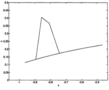
CHAPTER 3. VEHICLE MODELING 39 0.5 0.45 0.4 0.35 0.3 N 0.25 0.2 0.15 0.1 0.05 O _1 -0.9 -0.8 -0.7 -0.6 -0.5 -1 -0.9 -0.8 -0.7 -0.6 -0.5
Figure 3.2: An Odyssey fin, as modeled. Gertler [14]. The hull radius a varies with axial position by
a2 = 0.0088x6+0.0113x5+0.0018x4-0.0361x3-0.0804x2 +0.0182x +0.0736,
(3.1)
where the hull is defined on the domain
- 1.2049 < xhull < 0.9795. (3.2)
The fins are modeled using a straight-line outline as shown in Figure 3.2. A single thruster is mounted axially at the rear of the vehicle. Cruciform fins are located fore of the propeller arrangement. The vertical fins are called rudders; the horizontal fins are elevators.
A vehicle-fixed refernce frame {x, y, z} is employed with the coordinate axes directed forward, starboard, and down. The vehicle origin is set at the centroid of the hull. There are six degrees of freedom for vehicle motion, encompassing linear and angular velocities along each of the vehicle axes. These are refered to as surge, sway, heave, roll, pitch, and yaw. The general-ized velocities in these directions are u, v, w, p, q, and r, and the generalgeneral-ized forces are X, Y, Z, K, M, and N. For a survey-class vehicle, the surge velocity u is large compared to the other velocity components. A first-order model is produced by discarding the terms which involve the other velocity compo-nents, v, w, p, q, and r, nonlinearly. The resulting model is linear in these
VEHICLE MODELING
U( I
I
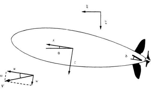
Figure 3.3: Variables used in the vertical plane vehicle model.
small velocities, but may include nonlinearities involving the surge velocity or vehicle attitude. This approach results in a model in which the verti-cal plane dynamics, involving surge, heave, and pitch, are decoupled from the horizontal plane dynamics, including sway, roll, and yaw. The model derivation will bear out this result.
This thesis focuses on controlling the vertical plane dynamics of the vehi-cle. Figure 3.3 illustrates the veriables used in describing the vertical plane dynamics. The elevator can be turned to an angle 6 with respect to the vehi-cle axis x. The vehivehi-cle frame of refernce {x, z} is rotated from the earth-fixed axes {(, (} with pitch angle 0.1 The total velocity in the vertical plane V is
'The relationship between the vehicle-fixed axes {x,y,z} and the earth-fixed axes {(, (r, (} for the general, coupled system is much more complex. See, for example, Waller
[30].
CHAPTER 3. 40
. : * _ f- ".
V
CHAPTER 3. VEHICLE MODELING
the vector sum of the surge and heave velocities,
V = V,2T+ w 2 (3.3)
and is directed at a sideslip angle a with respect to the vehicle axis x.
3.2
Vehicle Dynamics
3.2.1
Hydrostatic Forces
Vehicle weight and buoyancy give rise to hydrostatic forces and moments. Weight is always directed along the positive ( axis (toward the ocean floor), while buoyancy always acts in the negative ( direction (toward the surface). The following assumptions are made in considering vehicle hydrostatics:
* the vertical plane and horizontal plane dynamics are decoupled, * the vehicle is neutrally buoyant, and
* the vehicle is trim.
The assumption that the vertical plane dynamics are decoupled has been discussed already, and should hold if the vehicle has a relatively large surge velocity. Neutral buoyancy means that the vehicle weight is equal to its buoyancy. The vehicle is trim when there is no roll or pitch at rest; this means that the difference between the center of buoyancy and the center of
gravity lies entirely in the z direction.
Because the vehicle is assumed to be neutrally buoyant, there are no net hydrostatic forces. The separation between the centers of buoyancy and gravity does, however, produce a moment,
Mhydrostatic = -mgzG sin 0, (3.4)
where ZG is the distance between the centers of buoyancy and gravity. The weight of the vehicle is equal to the weight of the fluid displaced by the hull. This can be calculated by integrating (3.1):
m =
j
pira2dx = 359 kg, (3.5)hull
CHAPTER 3. VEHICLE MODELING
where the domain of integration is the same as the domain over which the hull is defined (3.2). Rehling [27] estimates
ZG = 0.05m, (3.6)
resulting in
Mhydrostatic = -175.91 sin 0. (3.7)
3.2.2
Inertial Forces
Inertial forces act on the vehicle due to the motion of the vehicle mass as well as the induced motion of the surrounding fluid. These forces can be rep-resented using tensors of mass coefficients. The induced forces and moments acting on the vehicle due to an inertia tensor mij are
F
j = -imji -ejk1Uifkmli
(3.8)
and
M
= -UiMj+3,i - ejkluiQkM+3,i- ejklUiUkmli, (3.9)where i = [1,2,3,4,5, 6], j, k, = [1,2,3], and summation over repeated indices is implied.2
Body Mass Forces
The body mass forces are forces on the vehicle due to the inertia of the vehicle itself. The following assumptions are made regaring the vehicle inertia:
* the difference between the centers of buoyancy and gravity lies entirely in the z direction, and
* the cross-products of inertia are negligible.
Applying equations (3.8) and (3.9) to the resulting body mass tensor
m 0 0 0 mzG 0 0 m 0 -mzG 0 0 mb= o 0 -mzG 0 I 0 0 (3.10) mzG 0 0 0 Iyy 0 0 0 0 0 0 I z
2For a derivation of this result and a discussion of its use for body mass and added
mass forces, see Newman [25, pp. 135-49].
CHAPTER 3. VEHICLE MODELING
and neglecting higher-order terms, the resulting body mass forces are
Xbody mass =
-mu
-mzGq,
Zbody mass = -mzb
+
muq, andMbody mass = -mzGu - Iyyci.
(3.11) (3.12) (3.13)
Iyy is estimated, as in Aguirre [2], using a homogeneous spheroid with the length and diameter of the vehicle,
L2
29
km
I = m=
91kgm2
(3.14) The resulting body mass forces areXbody mass = -359/i - 17.95q, (3.15)
Zbody mass = -359tb + 359uq,
and
Mbody mass = -17.95it - 914.
(3.16) (3.17)
Added Mass Forces
There are also inertial forces due to fluid motion induced by the vehicle. When the vehicle moves, a potential flow field is created. Because these forces can be represented by an inertia tensor, they are called added mass forces. The vehicle is symmetric with respect to the x, y- and x, z-planes. Consequently, the added mass tensor reduces to
ma
-ml
0 0 0 0 0 0 m22 0 0 m26 0 0 m3 3 0 m3 5 0 0 0 0 m4 4 0 0tO tO 0 0 m3 5 0 m55 0 0O m2 6 0 0 0 Mn6 6 -(3.18)Applying equations (3.8) and (3.9) and neglecting vertical plane added mass forces are
higher-order terms, the
Xadded mass = -mllU,
43
CHAPTER 3. VEHICLE MODELING
Zadded mass = -m3 3 tb - m35q + mlluq, and (3.20)
Madded mass = -m3 5 - m55q + m35uq
+
(m33 -mll)uw.
(3.21)
The surge added mass coefficient mill is determined by using a spheroidal approximation to the vehicle hull shape. Using potential flow theory, Blevins
[3, p. 407] calculates the surge added mass coefficient of a prolate sphereoid (a cigar shape) as
mil = 47rpD 3p, (3.22)
where is tabulated and depends on the length to diameter ratio. For the Odyssey hull shape,
/ = 0.3498, (3.23) yielding
mill = 30.59. (3.24)
Slender body theory was used to determine the remaining added mass coefficients: m33, m3 5, and m5 5. Since the vehicle forward velocity is assumed
to be large compared with its heave and pitch velocities, and the vehicle has a large length to diameter ratio, the added mass coefficients involving heave and pitch may be approximated by considering the two-dimensional added mass at a particular cross-section of the hull at a position xsection on the x axis. The heave velocity at such a section is
wsection = w - xsectionq. (3.25) If the section has a two-dimensional added mass coefficient ma(Xsection), then
the force acting on the section is equal to the change in the fluid momentum,
Zsection = at --
a
[ima(Xsection)wsection], (3.26)and the moment produced is
Msection = Xsection
at -
Ua
[a(Xsec ion)Wsection]. (3.27)Substantial derivatives are used here to account for momentum being con-vected along the hull. The total force and moment on the vehicle are the