Achieving Fault Tolerance via
Robust Partitioning and N-Modular Redundancy
by
Brendan Anthony O'Connell B.Sc. Computer Science University of Ottawa, 1993
Submitted to the Department of Aeronautics and Astronautics in Partial Fulfillment of the Requirements for the Degree of MASTER OF SCIENCE IN AERONAUTICS AND ASTRONAUTICS
at the
MASSACHUSETTS INSTITUTE OF TECHNOLOGY February 2007
©2007 Brendan Anthony O'Connell. All rights reserved.
The author hereby grants to MIT permission to reproduce and to distribute publicly paper and electronic copies of this thesis document in whole or in part
in any medium now known or hereafter created.
Signature of Author:
Certified by:
Certified by:
Accepted by:
MASSAI . iNS TUT -7,,. r ;
I
L.I 2 '..
3ARC
Department of Aeronautics and Astronautics January 17, 2007
Dr. Joseph A. Kochocki Thesis Supervisor, The Charles Star- Draper Laboratory, Inc.
Professor I. Kristina Lundqvist Thesis Advisor, Dipartment of 1Aonautics and Astronautics
.\\I ' Professor Jaime Peraire Chair, De arlhentT ommittee on Graduate Students
;HIVES
--Si -natre f Auhor
Achieving Fault Tolerance via
Robust Partitioning and N-Modular Redundancy
by
Brendan Anthony O'Connell
Submitted to the Department of Aeronautics and Astronautics on January 17, 2007 in partial fulfillment of the requirements for the
Degree of Master of Science in Aeronautics and Astronautics
ABSTRACT
This thesis describes the design and performance results for the P-NMR fault tolerant avionics system architecture being developed at Draper Laboratory. The two key principles of the architecture are robust software partitioning (P), as defined by the
ARINC 653 open standard, and N-Modular Redundancy (NMR). The P-NMR architecture uses cross channel data exchange and voting to implement fault detection, isolation and recovery (FDIR). The FDIR function is implemented in software that executes on commercial-off-the-shelf (COTS) hardware components that are also based on open standards. The FDIR function and the user applications execute on the same processor. The robust partitioning is provided by a COTS real-time operating system that complies with the ARINC 653 standard.
A Triple Modular Redundant (TMR) prototype was developed and various performance
metrics were collected. Evaluation of the TMR prototype indicates that the ARINC 653 standard is compatible with an NMR and FDIR architecture. Application partitions can be considered software fault containment regions which enhance the overall integrity of the system. The P-NMR performance metrics were compared with a previous Draper Laboratory design called the Fault Tolerant Parallel Processor (FTPP). This design did not make use of robust partitioning and it used proprietary hardware for implementing certain FDIR functions. The comparison demonstrated that the P-NMR system prototype could perform at an acceptable level and that the development of the system should continue. This research was done in the context of developing cost effective avionics systems for space exploration vehicles such as those being developed for NASA's Constellation program.
Technical Supervisor: Dr. Joseph A. Kochocki
Title: Principle Member of the Technical Staff, The Charles Stark Draper Laboratory Thesis Advisor: Dr. I. Kristina Lundqvist
Acknowledgements
I would like to thank everyone at Draper Lab who helped me during my stay here. I would especially like to thank Joe Kochocki, Roger Racine, Piero Miotto and Rob Hammett for their time and support. I would also like to thank Professor Kristina Lundqvist at MIT for her sound advice.
Also, a big thanks goes out to Gareth and Ann for supplying all the laughs over the phone. Finally, I would like to thank my father for always providing words of encouragement.
This thesis was prepared at The Charles Stark Draper Laboratory, Inc., under contract NNMO5AB50C, "CLV Task 6 Flight Software Engineering", sponsored by Jacobs Sverdrup Inc. and NASA Marshall Space Flight Center. Internal Draper support was also provided by project 21181, "GC Draper Fellows".
Publication of this thesis does not constitute approval by Draper or the sponsoring agency of the findings or conclusions contained herein. It is published for the exchange and stimulation of ideas.
Brendan O'Connell January 17, 2007
Table of Contents
1 Introduction ...
13
1.1 Cost Effective Avionics for Space Exploration ... 13
1.2 Research Objectives ... 17
1.3 T hesis O utline ... 20
2 Background ...
23
2.1 NASA Human-Rating Requirements... ... 23
2.2 Safety Critical Software Development Standards... ... 25
2.2.1 NASA Software Safety Standard...25
2.2.2 RTCA/DO-178B ... 26
2.3 Fault Tolerant Computing Concepts...27
2.3.1 Computer Channels... ... 28
2.3.2 C C D L ... ... 29
2.3.3 Byzantine Faults... ... 30
2.3.4 Synchronous vs. Asynchronous Channels ... 31
2.3.5 Channelized vs. Global Data Bus ... ... 33
2.4 Common Fault Tolerant Architectures ... ... 34
2.4.1 Dual and Triple Self Checking Pairs ... .... 34
2.4.2 N-Modular Redundancy with FDIR ... .... 36
2.5 Integrated Modular Avionics and Robust Partitioning ... 40
2.5.1 ARINC Background... ... 41
2.5.2 ARINC 651 -Integrated Modular Avionics ... 41
2.5.3 ARINC 653 -Robust Partitioning... ... 45
2.5.4 Example ARINC 653 Systems... ... 48
2.6 R elated R esearch... ... 51
3 P-NMR System Architecture ...
...
...
55
3.1 O verview ... ... 55
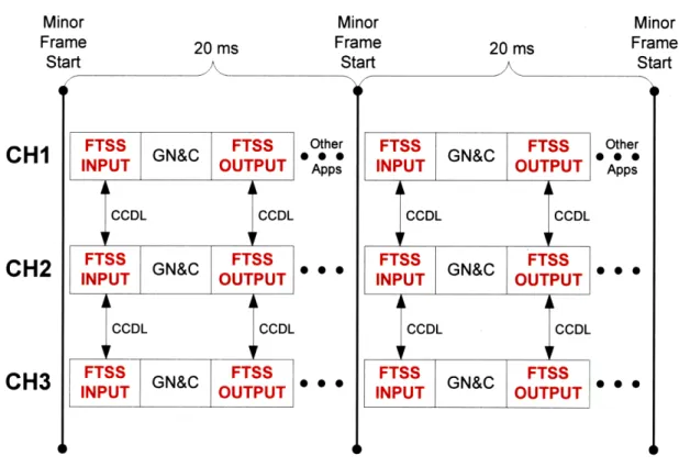
3.2 A Frame Synchronous Approach... 58
3.3 Simulated Channelized Data Bus Architecture...60
3.3.1 Sensor Input Processing by FTSS ... 62
3.3.2 Application Output Processing by FTSS ... .. 66
3.4 Channel Hardware ... 67
3.4.1 SBC750GX Single Board Computer ... 69
3.4.2 G bE C C D L ... 71
4 P-NMR Software Design ...
...
...
73
4.1 Channel Software Overview ... 73
4.1.1 Application Partitions and the APEX API...75
4.1.2 vThreads: The Partition O S ... 76
4.1.3 The core OS, FTSS and the BSP ... 77
4.1.4 XML System Configuration Files... 78
4.2.1 D esign G oals ... ... ... 80
4.2.2 Run-Time Implementation...82
4.2.3 Scheduling core OS FTSS Tasks ... ... 83
4.2.4 Rationale for placing FTSS in the core OS... 84
4.3 GbE CCDL Device Driver...85
4.3.1 Core O S D river M odel ... 85
4.4 Fram e Synchronization ... ... ... 86
4.4.1 The ARINC 653 Partition Schedule ... 87
4.4.2 PowerPC DEC Register and Core OS Kernel Ticks...89
4.4.3 PowerPC Time Base Register... ... 90
4.4.4 Steady State Frame Synchronization Algorithm...91
4.4.5 Scheduling the FTSS SYNC Partition ... .... 95
4.4.6 The FTSS sync task ... ... 96
4.4.7 Frame Synchronization After System Cold Start...100
4.4.8 Impact of Frame Synchronization on Robust Time Partitioning ... 102
4.4.9 Sum m ary ... 105
4.5 Scheduling FTSS Input/Output Processing ... .... 106
4.5.1 Scheduling Data Bus I/O ... 106
4.5.2 ARINC 653 Partition and Process Scheduling Overview...107
4.5.3 Implicit FTSS I/O Scheduling ... ... 109
4.5.4 Explicit FTSS I/O Scheduling ... 13
4.5.5 Channel Specific Schedules ... 123
4.5.6 Sum m ary ... 124
4.6 Fault Tolerant ARINC 653 Ports ... ... 125
4.6.1 Communication Channel and Port Overview ... 125
4.6.2 Sampling and Queuing Ports ... 127
4.6.3 Pseudo Partitions and Ports... 129
4.6.4 The P-NMR Port Design... ... 130
4.6.5 Summary ... 141
4.7 FT SS V oter ... ... 142
5
P-NMR System Performance Results...
143
5 .1 O verview ... ... 14 3 5.2 Data Collection M ethods ... 143
5.3 CCDL Gigabit Ethernet Performance ... 144
5.4 Time to Process One Kernel Tick ... 145
5.5 Frame Synchronization Performance... ... 146
5.5.1 Observed Relative Clock Drift... 146
5.5.2 Accuracy of 4000 DEC Interrupts Per Second ... 147
5.5.3 Frame Synchronization Performance ... 147
5.6 FTSS Input Exchange Performance ... 149
5.7 APEX Port System Call Performance...150
5.8 FTSS Output Exchange Performance... 152
5.9 Comparison with X-38 FTPP ... 152
6.1 Use of 6.2 Use of 6.2.1 6.2.2 6.2.3 6.3 Future 6.3.1 6.3.2 6.3.3 6.3.4
ARINC 653 with an NMR Architecture...155
C O T S ... 157
COTS ARINC 653 RTOS and DO-178B Certification ... 157
COTS ARINC 653 RTOS Performance ... 158
COTS Hardware for Fault Tolerance... ... 159
W ork ... 160
FTSS Im provem ents ... ... ... 160
Software Fault Containment Regions ... .... 161
Scheduling... 162
Configuration Files and Static Analysis Tools ... 163
References ...
165
Appendix A Acronyms ...
171
Appendix B XML System Configuration Files ...
73
B.1 Partition Schedule ... 173
B .2 P orts ... ... 174
B.3 Communication Channels ... ... 176
B .4 Port G roups ... ... 178
Appendix C GbE CCDL Driver Details ...
179
C.1 IEEE 802.3 MAC Frame Structure ... 179
C. 1.1 Ethernet Frame Check Sequence ... ... .... 179
C.2 DMA, SDRAM and the PowerPC Cache ... .... 180
C.3 Polled Mode vs. Interrupt Mode ... 182
C.3.1 Sending Data... 182
C.3.2 Receiving Data ... ... 183
C.3.3 Protection Against a Babbling Node...183
C.4 Static CCDL Configuration Table ... 184
C.5 Alternate Design: Partition Level CCDL Device Driver ... 184
Appendix D FAA Regulations and Guidelines...187
D. 1 Airworthiness Regulations ... 187
List of Figures
Figure 1.2-1 P-NMR Architectural Themes ... ... 20
Figure 2.4-1 X-38 FTPP (Courtesy Draper Laboratory) ... 38
Figure 2.5-1 Federated Avionics to Integrated Modular Avionics (IMA)... 43
Figure 3.1-1 P-NMR System Overview... ... ... 57
Figure 3.1-2 P-NMR System Prototype in Lab ... ... 57
Figure 3.2-1 P-NMR Frame Synchronous Approach ... 59
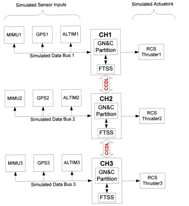
Figure 3.3-1 P-NMR Simulated Channelized Data Bus Architecture ... 61
Figure 3.3-2 Sensor Input Processing by FTSS ... ... 63
Figure 3.3-3 GN&C FDIR partition added to schedule ... 65
Figure 3.3-4 Application Output Processing by FTSS ... 67
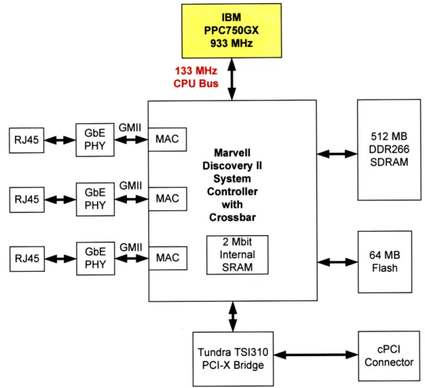
Figure 3.4-1 SBC750GX Board Components ... 70
Figure 4.1-1 Channel Software Overview ... ... 74
Figure 4.2-1 Application Output Detour to FTSS ... ... 81
Figure 4.4-1 ARINC 653 Partition Schedule ... 88
Figure 4.4-2 Steady State Frame Sync Algorithm ... ... 93
Figure 4.4-3 Clock Adjustment Algorithm ... .... ... 95
Figure 4.4-4 Major Frame Synchronization... 98
Figure 4.4-5 Clock Synch Algorithm using DEC Register... 101
Figure 4.5-1 I/O Processing added to partition schedule ... 107
Figure 4.5-2 Implicit Scheduling of FTSS I/O in Partition Schedule... 112
Figure 4.5-3 Explicit Scheduling of FTSS I/0 in Partition Schedule... 116
Figure 4.5-4 Explicit Scheduling of FTSS with APEX Ports... 119
Figure 4.5-5 First 20 ms minor frame ... 120
Figure 4.5-6 Timing within FTSS Input Task ... 122
Figure 4.5-7 Channel Specific Schedules ... 124
Figure 4.6-1 Different Partitions using FTSS services ... 135
Figure 4.6-2 Port Groups Assigned to Schedule Windows ... 138
List of Tables
Table 2.2-1 Table 2.5-1 Table 4.5-1 Table 4.5-2 Table 4.6-1 Table 4.6-2 Table 4.6-3 Table 4.6-4 Table 4.6-5 Table 4.6-6 Table 4.6-7 Table 4.6-8 Table 5.3-1 Table 5.5-1 Table 5.5-2 Table 5.6-1 Table 5.7-1 Table 5.8-1DO-178B Software Levels and Objectives ... 26
ARINC 653 Avionics Systems ... ... ... 51
Process Al System Call Durations... 111
GN&C Apex Processes ... 114
GN&C Partition Input Ports ... 131
FTSS_INPUT Pseudo Source Ports going to GN&C... 132
Sensor Input Channels Between FTSS_INPUT and GN&C... 133
GN&C Partition Output Ports ... 133
FTSS_OUTPUT Destination Ports... 134
Command Output Channels Between GN&C and FTSS_OUTPUT ... 134
FTSS_INPUT Sensor Port Groups For GN&C Partition ... 137
Example of Asymmetric Inputs... 141
CCDL Gigabit Ethernet Latency (t_del for 40 bytes) ... 145
Relative Clock Drift Between Channels... 147
CH1 Frame Synchronization Events ... 148
FTSS Input Performance ... 150
APEX Port System Call Performance ... 151
Chapter
1
Introduction
1.1 Cost Effective Avionics for Space Exploration
NASA and its industrial partners have started to implement the Constellation program, an ambitious plan to extend human presence across the solar system, starting with a human return to the Moon by the year 2020, in preparation for human exploration of Mars and other destinations [1]. Constellation is a family of vehicle elements that must operate in concert with each other in order to achieve mission goals. Some of the elements will be mated together to form larger elements. Thus, Constellation follows a system-of-systems (SoS) architecture. In order to reduce costs, many of the vehicles will share common subsystems.
One area in which the Constellation vehicles will differ substantially from their Apollo era counterparts is the avionics subsystem [2]. This is due to the digital technology revolution that has occurred since the 1960's. The throughput of today's processors and the capacity of memory far exceeds what was available when Apollo was
designed. This allows Constellation avionics designers to implement powerful new functionality in software such as autonomous operations and integrated vehicle health management (IVHM). This will enable some of the Constellation vehicles to operate with or without a human controller [2].
In addition to having increased functionality, the avionics systems will also have to be safe and reliable. This is especially true for the flight control function on a crewed vehicle where a fault could result in the loss of the vehicle and the crew. NASA requires that any system used on a human-rated vehicle be two-fault tolerant [3]. That is to say, the system must continue to operate correctly even after experiencing two faults.
A common avionics architecture that can provide robust fault tolerance is N-Modular Redundancy (NMR) with fault detection, isolation and recovery (FDIR). In this kind of system, identical software executes on N identical redundant computers (called channels). The computers communicate with each other over a cross channel data
link (CCDL). Sensor inputs are distributed to each computer and actuator command outputs from each computer are collected and voted to mask out any potential faults in one or more of the computers. Since voting is used, there needs to be at least three computers (N > 3). A three computer system (N = 3) is called a triple modular redundant (TMR) system.
A significant advantage of an NMR system with cross channel data exchange and voting is that it allows for the detection of a faulty computer. This computer can then be removed from the operational group of computers, reset and then readmitted back into the group. However, the exchange of data between channels also means that this kind of system is susceptible to so called Byzantine faults [4]. A Byzantine fault is an exceptionally difficult kind of fault to tolerate because it is not symmetrical. Different parts of the redundant computer system will see different results that are due to the same single fault. Thus, a Byzantine fault is classified as being asymmetrical. This asymmetrical nature can lead to disagreement among the redundant computers, especially during voting activities. However, a properly designed NMR system can correctly detect and isolate components that are generating Byzantine faults.
Since NMR with FDIR systems have been used extensively in previous flight control applications for both aircraft and spacecraft [5], it is a leading candidate architecture for ensuring avionics reliability on both manned and unmanned Constellation vehicles.
Another aspect of the avionics system that is related to reliability is dynamic reconfiguration. Reconfiguration could occur after a permanent fault in one of the computers. The software that was executing on the failed computer may need to be migrated to a healthy computer. This is especially applicable to long duration missions lasting several years where permanent equipment failures are possible. Reconfiguration of the avionics may also occur due to a reconfiguration of the vehicle itself. An example of this is when two orbiting vehicles dock together. It may be advantageous to have the computers on both vehicles form a single fault tolerant group.
The combination of functionality, reliability and reconfiguration requirements can result in an avionics system that is complex and difficult to verify and validate. A significant portion of the verification effort could be spent integrating hardware and
software from many different internal and external suppliers. These individual components may not use common standards resulting in a difficult system integration and test phase.
One way in which NASA could significantly reduce the complexity and cost of avionics system development is to minimize the use of custom or proprietary hardware and software components. Instead, NASA should maximize the use of proven commercial off-the-shelf (COTS) components that are based on open standards and that have been widely adopted within one or more industries. An open standards approach promotes reusability, extensibility and maintainability of the avionics system and it tends to reduce design and development costs [6]. It also minimizes the chance of obsolescence issues associated with proprietary products from a single vendor. This approach of using open standards and COTS has already been adopted by the commercial and military avionics industry [7, 8, 9].
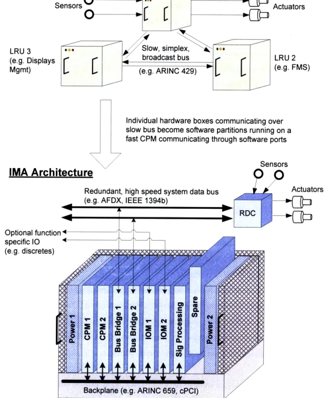
One commercial avionics standard that may be applicable to Constellation projects is ARINC 651 which provides design guidance for integrated modular avionics (IMA) [10]. Over the last decade, aircraft manufacturers have moved away from traditional distributed federated avionics systems towards IMA [11, 12]. In a federated system, each individual avionics function, such as collision avoidance, is implemented as a separate hardware box on the aircraft. Each box has its own chassis, backplane, power supply, processor, memory and I/0 hardware. All the individual avionics boxes are then connected together with point-to-point data buses. However, in an IMA system, multiple functions are hosted within a single, standardized IMA cabinet.
Inside the IMA cabinet are standardized "modules". Examples include power supply modules, processing modules and I/O modules. The modules may communicate with each other over a backplane within the cabinet. In most cases, multiple avionics functions will share the same processor and memory on one module. In effect, individual avionics functions share common resources. One function can communicate with another using software instead of physical wiring. The advantages of an IMA architecture include a reduction in avionics size, weight, power consumption and wiring complexity [10]. Size and weight savings are critical for any Constellation vehicle being launched into space.
In order for an IMA architecture to be viable in a safety critical environment such as transport aircraft avionics, a mechanism must be provided that greatly reduces the risk of one function interfering with another function within the same IMA platform. This is especially true when the two functions have different criticality levels. For example, one function could be responsible for automatically landing the aircraft in bad weather whereas the other function could be responsible for maintaining the passenger cabin temperature. Obviously, the cabin temperature function must not interfere in any way with the autoland function.
This isolation of different functions is provided by a concept called robust partitioning. Robust partitioning is implemented by the real time operating system
(RTOS) that is running on each processor within the IMA cabinet. Each avionics function is called an application and each application is placed inside a partition. A partition can be thought of as a protective container for the application. The RTOS provides three main types of partition protection: time, space and I/O. These are explained more in section 2.5.3. Rather than have each avionics supplier develop its own version of an RTOS that supports robust partitioning, the commercial avionics industry has moved towards a single open standard for robust partitioning. The ARINC 653 standard defines the robust partitioning requirements for an RTOS kernel as well as the aiplication executive (APEX) application programming interface (API) [13]. The APEX API defines a standard set of robust partitioning services that an application programmer can use. There are currently at least five COTS RTOS products that support the standard.
A significant advantage of using the ARINC 653 standard and the APEX API instead of a custom solution is that avionics applications are portable and reusable. They are not tied to a single RTOS product from a single vendor. An application that follows the APEX API can be moved from one COTS ARINC 653 RTOS to another without having to edit and retest the application code. All that is required is a recompile. This advantage is significant for a large and long duration program like Constellation where several RTOS vendors may be used over the lifetime of the program.
Another important standard that is closely related to ARINC 653 compliant COTS products is RTCA/DO-178B, "Software Considerations in Airborne Systems and Equipment Certification" [14]. This standard provides guidelines for the production of
software for aircraft avionics systems such that there is a reasonable expectation that the software will perform its intended function and will be free of serious defects. The guidelines illustrate how development processes can be setup for each phase of the software development lifecycle (e.g. requirements, design, code, verification) and it specifies objectives that should be met for each process. It also specifies what kinds of evidence can be used to prove that the objectives were satisfied during the development process. This evidence can then be used when the certification process begins for the aircraft.
Given the expense of developing an ARINC 653 RTOS using DO-178B guidelines, RTOS vendors have started to create a certification package. This package is an optional product that can be purchased in addition to the RTOS itself. The package contains all the required evidence and documentation that shows how each DO-178B process objective was met. Thus, the cost of using DO-178B software development processes can be spread among multiple RTOS customers. An avionics system supplier can simply purchase the COTS RTOS product and the DO-178B certification package off-the-shelf. This allows the avionics supplier to focus on their core business instead of spending time and resources collecting DO-178B evidence required for using the RTOS in the final certified system.
If NASA decided to accept DO-178B certification packages from commercial RTOS vendors then a significant cost saving could be had on Constellation avionics projects. However, if there is an intent to use the certification package then the COTS product should not be altered or customized by the avionics system developer.
The challenge for NASA and its industrial partners is applying open standards, COTS and commercial avionics technology in a way that still provides an avionics system that is safe, reliable and cost effective.
1.2 Research Objectives
The following issues are associated with the described approach to cost effective avionics for space exploration.
First, there are few examples in the literature of an ARINC 653 compliant RTOS with the APEX API being used for NMR flight control computers (FCCs). Most previous
applications of the ARINC 653 standard have been for IMA based mission management computers (MMCs) that are not responsible for flight control and that do not use an NMR with FDIR architecture. Instead, only two MMCs are used; one is the primary and the other is a backup. Thus, a typical configuration on an aircraft may be a pair of IMA based MMCs that use ARINC 653 and another group of voting NMR FCCs (N >= 3) that perform the flight control function and that do not use ARINC 653. Given that Constellation vehicles have severe size and weight constraints, they cannot afford two different sets of computers. The FCCs and MMCs must be integrated into a single group of vehicle management computers (VMCs) that host both the flight control and mission management functions.
Second, it has not been established that a COTS ARINC 653 RTOS can be used in an NMR with FDIR architecture without substantial modifications. It is also not clear if a COTS RTOS has sufficient performance for such an application. The impact of the RTOS on processor throughput and latency needs to be evaluated. Any modification of the COTS kernel to change behavior or to improve performance could render significant portions of the COTS DO-178B certification package invalid.
Third, most previous fault tolerant NMR avionics systems used for flight control have used some proprietary hardware to implement portions of the FDIR functionality. Few NMR systems implement the fault tolerance and redundancy management functions in software executing on COTS hardware. An often stated rationale for this approach is concerns over the performance of COTS hardware.
Given the above issues, this research attempts to answer the following questions:
1. Is the ARINC 653 standard for robust partitioning, specifically the APEX API, compatible with an NMR/FDIR architecture? The focus is on two main areas:
a. How can the ARINC 653 two-level scheduler be used to schedule fault tolerance processing such as sensor input distribution and output voting? b. How can APEX communication ports be adapted to fault tolerant I/O
2. Can a COTS ARINC 653 RTOS be used in a fault tolerant NMR voting architecture without substantial modifications?
a. How can the fault tolerance functions be integrated with the COTS RTOS product?
b. What is the performance of the COTS RTOS product? This includes evaluating the ARINC 653 scheduler and the APEX port I/O facilities. 3. Can widely adopted COTS computer components be used to implement a fault
tolerant NMR voting architecture? Is custom proprietary hardware necessary? Can the fault tolerance functions be implemented in software executing on a COTS processor? What is the performance of the system?
In order to answer these questions, a system prototype was developed. The system design uses a partitioned, NMR approach, and is thus referred to as a P-NMR architecture. It uses COTS hardware and software and open standards such as ARINC 653 and IEEE Standard 802.3 (Ethernet). Various performance metrics were collected and compared to a previous NMR system built by Draper Laboratory, the X-38 Fault Tolerant Parallel Processor (FTPP). This system was developed for NASA in the late 1990's and it does not use ARINC 653 robust partitioning and it does use custom hardware to implement certain FDIR functions.
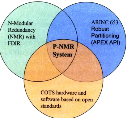
In summary, this research will use the P-NMR prototype to investigate the concurrent use of three main architectural themes to develop a cost effective, fault tolerant avionics architecture for space vehicles such as those being developed for the Constellation program. These three main architectural themes, as shown in Figure 1.2-1, are N-modular redundancy with FDIR, ARINC 653 robust partitioning and COTS hardware and software based on open standards.
Figure 1.2-1 P-NMR Architectural Themes
1.3 Thesis Outline
Chapter 2 provides background and related research on reliability requirements, fault tolerant avionics and robust partitioning. Chapter 3 describes the P-NMR system architecture at a high level and includes a description of the COTS hardware components being used for each redundant computer in the TMR prototype. Chapter 4 is a detailed description of the software executing on each redundant computer. It discusses in depth how the fault tolerance functions have been implemented in software and how they have been integrated with the COTS ARINC 653 RTOS. Chapter 5 presents the performance results for the P-NMR prototype and compares these results with the Draper Laboratory X-38 FTPP system. Chapter 6 presents our conclusions including whether or not the ARINC 653 standard and the APEX API are compatible with an NMR and FDIR architecture. Chapter 6 also suggests areas for future research using the P-NMR prototype. Appendix A is a list of acronyms, Appendix B provides some examples of the P-NMR Extensible Markup Language (XML) system configuration files, Appendix C provides details on the implementation of the CCDL using COTS Ethernet hardware and
Appendix D contains a sample of reliability requirements and guidelines from the commercial aircraft industry including guidelines for IMA systems.
Chapter 2
Background
This chapter provides some background and related research on reliability requirements, fault tolerant avionics and robust partitioning. Section 2.1 describes certain NASA human-rating requirements that are relevant to any avionics system architecture being proposed for crewed vehicles. Section 2.2 is a brief description of two safety critical software development standards, one used by NASA and the other used by the aircraft industry. Section 2.3 discusses some fault tolerant computing concepts often used when describing avionics systems. Section 2.4 discusses two common fault tolerant avionics architectures: self checking pairs and N-modular redundancy. Section 2.5 talks about IMA, robust partitioning via ARINC 653 and some existing systems that currently use an ARINC 653 compliant RTOS. Finally, in section 2.6, there is a literature review of research related to robust partitioning and fault tolerance.
2.1 NASA Human-Rating Requirements
This section discusses certain NASA reliability requirements that will affect the design of any avionics system being proposed for use on a crewed NASA space vehicle. For comparison purposes, similar requirements for transport aircraft are described in Appendix D.
Compared to aircraft, spacecraft and their avionics have to operate in a harsh environment. There is severe vibration during launch. While in space, the avionics may be exposed to vacuum conditions and there may be large temperature extremes. Avionics components may be exposed to solar and cosmic radiation. This radiation can lead to single event effects (SEE) such as single event latchups (SEL) and single event upsets (SEU) that may induce a computer reset. Thus, avionics reliability for human-rated vehicles must be carefully considered.
The NASA procedural requirements for the human-rating of space systems is contained in [3]. Reliability is defined as the probability that a system of hardware,
software, and human elements will function as intended over a specified period of time under specified environmental conditions. A fault is a defect, imperfection, mistake, or flaw of varying severity that occurs within some hardware or software component or system. Fault is a general term and can range from a minor defect to a failure. The term failure is not defined. Fail-safe is defined as the ability to sustain a failure and retain the
capability to safely terminate or control the operation.
The human-rating standard requires that all space systems that will support humans be designed such that no two non-simultaneous failures result in crew or passenger fatality or permanent disability. In other words, systems must be "fail-op, fail-op". In systems with relatively short periods of operation, or where dynamic flight modes (such as powered ascent) are involved, NASA suggests that installed redundancy be the principal means of ensuring the system's reliability. The system must also provide an FDIR mechanism for faults that affect critical functions.
The standard also has specific requirements for flight control systems that will be used on a human rated vehicle. Specifically, the system design shall prevent or mitigate the effects of common cause failures in time-critical software (e.g., flight control software during dynamic phases of flight such as ascent). An example of a common cause failure is where the same microprocessor is used in redundant flight control computers. If the microprocessor has a design flaw (e.g. in the floating point unit), it may affect all redundant computers at the exact same time since the computers may all be executing the same software. Such a flaw may be difficult to detect since all computers will produce the same answer. Common cause failures can be avoided by using dissimilar hardware and/or software. Some of the methods suggested by NASA for meeting the intent of this requirement include:
1. Redundant independent software running on a redundant identical flight computer.
2. Use of an alternate guidance platform, computer and software (e.g., using the space craft guidance to control a booster).
3. Use of nearly identical source code uniquely compiled for different dissimilar processors.
2.2 Safety Critical Software Development Standards
2.2.1 NASA Software Safety Standard
The NASA standard for the development of software for space vehicles and their associated ground equipment is contained in [15]. There are only two main classes of software: safety critical and mission critical. Software is safety-critical if it meets at least one of the following criteria:
1. Resides in a safety-critical system (as determined by a hazard analysis) AND at least one of the following:
a. Causes or contributes to a hazard.
b. Provides control or mitigation for hazards. c. Controls safety-critical functions.
d. Processes safety-critical commands or data.
e. Detects and reports, or takes corrective action, if the system reaches a specific hazardous state.
f. Mitigates damage if a hazard occurs.
g. Resides on the same system (processor) as safety-critical software. 2. Processes data or analyzes trends that lead directly to safety decisions.
3. Provides full or partial verification or validation of safety-critical systems, including hardware or software subsystems.
Mission critical software is defined as software which must retain its operational capability to assure mission success. An example would be software associated with the collection of science data on the surface of a planet.
Of note is that any software that resides on the same processor as safety-critical software is also deemed safety critical. However, the standard goes on to indicate in a note that methods to separate the code, such as partitioning, can be used to limit the software defined as safety-critical. If such methods are used, then the isolation method is safety-critical, but the isolated non-critical code is not.
Regarding COTS software, the NASA software standard indicates that including software in a safety-critical system when the software was not developed specifically for that system "can be risky". The requirements go on to state that COTS used in
safety-critical systems shall undergo safety analysis that considers its ability to meet required safety functions. This analysis must include the evaluation of functions not planned to be used during a mission but present in the COTS product.
2.2.2 RTCA/DO-178B'
In terms of aircraft, the Federal Aviation Administration (FAA) has indicated that avionics developers may use RTCA/DO-178B as a means to secure FAA approval of digital computer software. It should be noted that the FAA does not mandate that avionics software developers use DO-178B. They may use other methods that satisfy the intent of DO- 178B. It should also be noted that DO- 178B is not a set of requirements that must be followed exactly. It is more a set of guidelines that can be customized to some degree.
DO-178B defines five failure condition categories based on their impact on continued safe flight of the aircraft. These failure categories are catastrophic, hazardous, major, minor and no effect.' The document also defines five software levels, A through E, based on the contribution of software to potential failure conditions. The software level determines how rigorous the software development process must be and it determines how many objective must be satisfied during the development process. Table 2.2-1 shows the failure conditions, software levels and the number of development process objectives that must be satisfied. As can be seen, Level A software has the most objectives and is thus very expensive to develop and verify.
Failure Condition
Software
Number of
Level Objectives Catastrophic A 66 Hazardous/Severe-Major B 65 Major C 57 Minor D 28 No Effect E 0
Table 2.2-1 DO-178B Software Levels and Objectives
In terms of robust partitioning, DO-178B states that the technique can be used to provide isolation between functionally independent software components to contain and/or isolate faults and potentially reduce the effort of the software verification process. The standard goes on to state that if protection by partitioning is provided, the software level for each partitioned component may be determined using the most severe failure condition category associated with that component. Also, if some of the partitioning protection is provided by software as opposed to hardware, then that software must be assigned the software level corresponding to the highest level of any of the application partitions using the protection mechanisms.
COTS software must be assigned the appropriate level and the vendor must use appropriate software development processes that satisfy the intent of the objectives in DO-178B. The vendor must produce all evidence that is required to prove that appropriate processes were followed during the software development lifecycle.
2.3 Fault Tolerant Computing Concepts
This section discusses some common concepts used in the context of safety critical, fault tolerant computer architectures.
The primary method used for achieving fault tolerance in safety critical applications is redundant software executing on redundant hardware. The main reason for using this kind of redundancy is that it provides fail-operational capability. After experiencing a single failure in one hardware component, the system can continue to operate without interruption. This type of redundancy uses "hot" redundant hardware components meaning that they are always powered on and operational. One computer may be the primary but all the standby computers are processing all the same inputs as the primary. A "cold spare" approach uses redundant computers and components that can be powered off - they are only powered on after a failure occurs. A hot redundancy approach is essential for time critical functions such as flight control.
Another main advantage of redundancy is that it aids in fault detection. For example, the outputs from redundant processors executing identical software using identical sensor inputs can be compared. A miscompare of the outputs indicates that one of the processors has experienced a fault.
Using redundancy to identify faulty hardware is especially important if the built-in test (BIT) functionality native to the hardware components (e.g. circuit boards) cannot guarantee that 100% of all possible hardware faults will be detected. BIT functionality will execute at power up and it will execute continuously (CBIT) during normal operation. An example of hardware BIT is memory integrity tests. In general, BIT functions cannot detect 100% of all possible hardware faults in a current generation
single board computer [5].
The main disadvantages of active redundancy is an increase in avionics cost, size, weight, power consumption and complexity. Although redundancy will increase operational system reliability, there is an increase in the arrival rate of faults simply because there are more components on the vehicle that can fail. This can lead to increased maintenance costs, increased spares inventory and a decreased dispatch rate. Depending on the avionics architecture, increasing the number of redundant computers can also decrease overall system throughput and bandwidth. Thus, there is a trade that needs to be made between increasing reliability using more redundancy versus all of the mentioned drawbacks.
2.3.1 Computer Channels
A hardware channel is a fault containment region (FCR). An FCR is a set of
hardware elements that provides physical separation, independent power, electrical isolation and independent clocking. A fault that occurs within one channel cannot escape to (or pollute) another healthy channel. This includes incorrect data as well as physical threats such as an electrical power surge.
A channel is usually a single computer chassis since it contains some simplex
elements that all the modules within the chassis share such as a single power supply or a single backplane bus.' Thus, a single event such as a power surge could damage all the modules within one chassis. This is why the chassis is considered the channel and not the individual boards within the chassis. All safety critical, fault tolerant avionics designs
will contain at least two physically separated channels that use independent power supplies.
Note that the components within each redundant channel do not necessarily have to be homogeneous. For example, a different type of processor could be used in each channel. This would avoid common mode failures due to a design flaw in a particular type of processor. However, heterogeneous components in each channel can make timing analysis more difficult as the processors will take different amounts of time to execute the same source code. We also note that there may be redundancy within a channel. For example, a single printed circuit board within a single channel may contain two lockstep processors whose outputs are compared. Combining these two ideas, an architecture could consist of N identical channels with each channel containing two different types of processors.
Related to this discussion is the notion of a single dissimilar backup channel. As an example, a primary flight control system may use four identical channels. It is possible that a common mode fault will cause all four primary channels to fail at the same time. Thus, a fifth channel that uses different hardware and software may be desirable. The hardware and software design and development for the backup system may be performed by a different organization using different personnel to reduce the use of common design assumptions. The introduction of a backup system that uses dissimilar hardware and dissimilar software developed by a separate team of engineers can significantly increase the cost and complexity of the avionics design. The backup systems ability to increase reliability is also controversial [16].
The P-NMR system prototype uses three channels, each with a single processor of the same type, as discussed in section 3.1.
2.3.2 CCDL
An important aspect of many fault tolerant computing designs is the notion of communication between channels. One reason for this communication would be to allow the comparison of the outputs of each channel in order to identify faults. This communication is implemented using a cross channel data link (CCDL). The physical
CCDL medium and the methods used for exchanging data between channels is critically important because the CCDL connects all redundant channels together and thus it could be the source of a common mode failure. The CCDL functionality has the ability to corrupt or damage all redundant channels simultaneously, nullifying any benefits of
redundant hardware.
The P-NMR architecture uses a point-to-point CCDL which is described in section 3.4.2 and Appendix C.
2.3.3 Byzantine Faults
In the landmark paper by Lamport et al [4], the authors introduce the notion of a Byzantine fault. This is the most difficult type of fault to be tolerated by a group of three or more channels that use some form of cross channel voting to identify a faulty channel. The difficulty lies in the fact that different channels will observe the fault in different ways. In essence, the fault is asymmetrical. In order to properly tolerate "f"' simultaneous Byzantine faults, there needs to be (3f + 1) channels and (f + 1) rounds of data exchange. Simultaneous means that the first fault is not corrected before the second fault occurs.
A two round data exchange (to tolerate just one Byzantine fault) starts with each channel sending all other channels a message indicating "this is my data". This is called round one. The second round involves all channels forwarding the round one data they received from other channels. In essence, the round two message indicates "here is the data I received from other channels during round one". As long as there are enough channels, this method of data exchange can properly identify a faulty channel.
Thus, the cost of handling Byzantine faults is high, both in terms of required hardware redundancy and in terms of the amount of communication required. For example, in order to tolerate two simultaneous faults, 7 channels and 3 rounds of data exchange are required.
The authors also show that if message authentication is used then only (f + 2) channels are required. Message authentication requires some form of secure digital signature and is computationally expensive [17]. Thus, redundant systems with a CCDL often use simpler forms of error detection and correction such as a cyclic redundancy
code (CRC) [18]. Since a CRC is not sufficient for message authentication, (3f + 1) channels are still required to tolerate "f' Byzantine faults.
The authors in [19] indicate that there has been a reluctance on the part of avionics designers to accept that a Byzantine fault is possible in an actual avionics system. However, they present several examples of actual occurrences in production systems and they explain how real hardware can produce Byzantine faults including slight-off-specification (SOS) timing faults. We also note that the design for the Boeing 777 fly-by-wire system takes into account Byzantine faults [20].
Finally, since Byzantine faults are especially difficult to tolerate, many fault tolerant designs do not use three or more channels that use cross channel voting schemes. Instead, a popular alternative is a series of self checking pairs, as is discussed in section 2.4.1.
The P-NMR software architecture has been designed to tolerate one Byzantine fault when four channels are used. However, the initial prototype only has three channels (N = 3) with no message authentication and thus some aspects of the software design were altered to accommodate this limitation.
2.3.4 Synchronous vs. Asynchronous Channels
A major decision for some fault tolerant designs is whether the system should be synchronous or asynchronous or some combination of the two. A synchronous system means that all redundant computers execute the same software using the same inputs at approximately the same time. If no faults occur then all channels should produce the same outputs. An asynchronous system, on the other hand, means that the individual channels do not need to be in lockstep with one another and do not have to use the exact same inputs at any given instant in time [21].
The advantage of synchronous systems is that it allows simple bit-for-bit, majority voting of the channel outputs. This is sometimes referred to as exact agreement. Exact agreement is possible because in the fault free case, all channels should produce identical outputs (e.g. actuator commands). The disadvantage of this approach is that it requires some form of distributed clock synchronization among the channels. In order for the
clock synchronization to be fault tolerant, a single clock source is not used. Instead, all the channels have their own local clock but they will use a distributed clock synchronization algorithm (using the CCDL) to "agree" on a global time to be used by all channels. Unfortunately, these kinds of algorithms can be susceptible to Byzantine faults that can lead to disagreement and clock divergence [22]. An example of this is slightly-off-specification timing errors in a CCDL transmitter. In addition, the special cases of system startup and the introduction of a new channel into a group of channels that are already synchronized is non-trivial.
The advantage of asynchronous systems is that no clock synchronization is required. The channels can operate autonomously. Each channel reads sensor values, executes the control laws and produces actuator commands. However, the channels may read the sensor values at slightly different times. This is especially true for high rate control loops executing at 25 Hz or higher. The disadvantage of this approach is that the command outputs from each channel may be slightly different and so simple bit-for-bit majority voting (i.e. exact agreement) cannot be used. Instead, approximate agreement methods must be used. This kind of agreement involves voting schemes such as median value selection (MVS) for three values or, in the case of four values, the average of the two middle values after removing the smallest and largest values. Reasonableness thresholds may also need to be defined. Finally, integrators used in the control laws on each channel will diverge over time producing significantly different outputs and so some form of channel equalization of key control law variables is required on a periodic basis [20, 21].
Finally, there is the concept of a globally asynchronous, locally synchronous (GALS) architecture. In this case, the channels are allowed to operate asynchronously. However, within each channel, there will be two or more processors that execute synchronously in lockstep. The lockstep processors are used to verify that an individual channel has not experienced a fault. The output value from the synchronous processors is then sent to some other part of the avionics system that will make a determination as to which channel's value will be used to command the actuators.
The P-NMR architecture uses a synchronous approach and is described more in section 3.2.
2.3.5 Channelized vs. Global Data Bus
Another important design decision is the topology for the data bus which connects the redundant computer channels to other components of the avionics system. Of primary importance is the method used to connect flight control sensors and actuators to the redundant channels. The data bus design is tightly coupled to the CCDL data exchange design and the timing design (i.e. synchronous or asynchronous). Two common data bus designs used in safety critical aerospace applications are channelized and global.
A channelized data bus topology dates back to the earliest fly-by-wire systems. Using this design, there is a set of sensors and actuators that are only connected to one channel using a single data bus. A single data bus with the sensors, single channel and actuators connected to it is sometimes referred to as a string. Each sensor and actuator only has one bus interface unit. Thus, if there are four channels then there will be four data buses and each data bus will be connected to only one channel and one set of sensors/actuators. Each channel may or may not be connected to the other channels using a CCDL. The advantage of this design is simplicity and isolation. One string cannot interfere or damage another string. A disadvantage is that the loss of the computer channel means the entire string is lost including the sensors and actuators attached to that channel. Another issue is that input congruency on each channel may necessitate sensor data exchanges across the CCDL.
A global topology connects all sensors and actuators to all channels. If there are four channels then there will be four data buses and each data bus will be connected to all four channels and all four sets of sensors. With this design there is no need to exchange sensor inputs using the CCDL between channels. The advantage of this design is that it is fault tolerant in the sense that if one channel fails, the remaining channels still have access to all sets of sensor devices. The disadvantage is complexity. Each sensor unit (or remote data concentrator) will have four bus interface units. The design is also susceptible to certain common mode faults. For example, since one bus connects all four channels together, a single power surge along the single bus could damage all the
channels. Another example would be when a "babbling node" or a "stuck on transmit" node on a single data bus interferes with all the channels.
The data bus design is also related to the channel timing design (synchronous or asynchronous). In a synchronous design, it may be desirable to have the bus controller on each channel request sensor data at the same time. Bus designs that use a time triggered approach instead of an asynchronous one are better suited for such applications [23].
The P-NMR architecture uses a channelized design and is described more in section 3.3.
2.4 Common Fault Tolerant Architectures
A thorough review of fault tolerant avionics architectures used in aerospace applications can be found in [5]. This section discusses two of those architectures which are relevant to this research.
2.4.1 Dual and Triple Self Checking Pairs
A self checking pair (SCP) is comprised of two processors executing the same software and comparing results. This is most commonly accomplished at the printed circuit board level where a single board has two processors that execute in lockstep using the same board level system clock. Usually, each processor has its own private main memory. Comparator hardware is used to compare the outputs of the two processors. The comparator may be on the same circuit board as the two processors or it may be an external device.
In general, exact agreement is used since the processors execute in lockstep. If the outputs agree then the output is sent to the actuator. If there is a disagreement, the output value is not used and the pair of processors is considered faulty. It is important to note that if there is only one SCP then it is difficult to determine which processor experienced a fault. BIT may be used to attempt to determine the faulty processor but this is not a guaranteed solution since BIT cannot obtain 100% fault coverage. Also, the
determination of the individual faulty processor is often not required since the entire circuit board is reset.
Normally, a single SCP board is contained within a single channel (i.e. computer chassis). A single SCP can prevent any malfunction but is twice as likely to experience a loss of function due to the fact that two processors are required to produce an output [5]. The probability of loss of function can be reduced if one processor is allowed to operate in simplex mode if BIT fails for one of the processors. The drawback of a single SCP board is that the two processors are in the same fault containment region (i.e. channel) and thus they are both susceptible to a single common area fault such as a fire. In some implementations, the two processors may also use the same power supply and clock.
In order to increase reliability, dual and triple SCPs are used. In the dual case, there are two channels in the avionics system. Each channel contains one board or module that has the SCP processors. The outputs from the SCPs are compared, either within each channel or at a location external to both channels. If the first SCP compare is good then its value is used otherwise the second SCP compare is performed. This can be extended to a three channel system. A dual SCP architecture is often used in IMA systems, as discussed in section 2.5.4.
An advantage of a dual or triple SCP architecture is that it does not require a distributed clock synchronization algorithm since clocking is only performed at the board level within a single channel. In general, these systems use a globally asynchronous, locally synchronous approach where the channels are not synchronized but the pair of processors within a channel are synchronized. Since the channels are asynchronous, some designs may require channel equalization of critical variables to prevent the gradual divergence of the channel outputs.
SCP designs also do not require majority voting or mid-value selection since a simple comparison of two values is used. This means that Byzantine faults are not possible since there needs to be at least three values being compared for an asymmetric fault to occur.
2.4.2 N-Modular Redundancy with FDIR
This section discusses distributed N-modular redundant (NMR) systems that use physically separated channels as opposed to NMR implementations that use three or more lockstep processors on a single printed circuit board.
A distributed NMR architecture involves using N channels with N > 3. Channels are connected using a CCDL. There is a dedicated, point-to-point CCDL between each pair of channels - a bus or network topology is not used for the CCDL. In order to accomplish FDIR, the channels exchange application outputs using the CCDL and then the outputs are voted within each channel. Exact or approximate voting methods can be used depending on whether the design is synchronous or asynchronous.
A design where N = 3 is called a triple modular redundant (TMR) design. A TMR system may be designed to use an SCP configuration after the first channel failure and a simplex channel after the second failure. If this is the case, the TMR design can prevent loss of function and malfunction after two consecutive symmetric faults. However, a TMR system cannot prevent a malfunction after a single Byzantine (asymmetric) fault. A quadruplex system (N = 4) can tolerate two simultaneous symmetric faults and one Byzantine fault.
NMR systems with FDIR often use some form of group membership protocol. This involves all channels exchanging system state information so that the channels can come to a consensus (using voting) on the health of each channel in the system. A channel that is deemed faulty by the majority will be removed from the operational group of channels and will be prevented from participating in any future votes. The faulty channel may be reset and then monitored by the operational group until the group deems that the reset channel is healthy again. At this point the channel will be readmitted back into the operational group and will be allowed to participate in voting.
In general, a TMR (N = 3) with FDIR system is more reliable than a single channel with an SCP [5, 24]. To provide the same fault protection as a quadruplex NMR system would require three SCPs [5]. However, NMR systems can be more complex than SCP systems, mainly due to the increased number of channels and the voting activities. Synchronous NMR systems that use a distributed clock synchronization algorithm can be especially challenging to develop [25].
The P-NMR architecture uses an NMR with FDIR design that is described more in Chapter 3.
2.4.2.1 NMR Example: X-38 FTPP
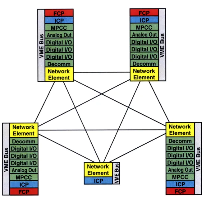
The performance metrics for the P-NMR prototype described in this thesis were compared with another Draper Laboratory avionics system called the Fault Tolerant Parallel Processor (FTPP). This system was developed by Draper Laboratory under contract to NASA Johnson Space Center for use on the now cancelled X-38 Crew Return Vehicle [26]. This system is an NMR design with FDIR. The example configuration shown in Figure 2.4-1 has four flight critical channels and one network element fifth unit (NEFU). Each channel is an FCR with its own power supply and internal clock source. There is a point-to-point CCDL between every pair of channels. The CCDL uses optical fiber for electrical isolation. The four channels and the NEFU operate synchronously using a distributed clock synch algorithm and a channelized data bus architecture is used for the sensors and actuators. The FTPP system is estimated to have an availability of 99.999%.
Each channel (except the NEFU) consists of a chassis with a Versa Module Eurocard (VME) backplane bus, a Flight Critical Processor (FCP) board, an Instrumentation Control Processor (ICP) board, a Multi-Protocol Communications Controller (MPCC) board, various I/O boards and a Network Element (NE) board. All components are COTS except for the NE board. The NE is at the heart of the fault tolerant architecture and performs such functions such as clock synchronization, group membership, input congruency and output voting. These functions are implemented in hardware using a field programmable gate array (FPGA).
The FCP hosts the flight critical guidance, navigation and control (GN&C) software application and it hosts some non-critical software applications. ARINC 653 partitioning is not used to isolate software applications. The ICP is responsible for performing I/O processing using the I/O boards. The four FCPs form a quadruplex virtual group. A virtual group is a novel way of grouping individual processor boards in each of the four channels into a fault tolerant group of processors. The ICP boards do not form a virtual
group and operate in simplex mode. The NE in each channel contains a configuration table that has the number of boards in the other channels as well as a description of the virtual groups.
i L
The X-38 avionics architecture uses a channelized data bus design where a set of sensors is only connected to a single channel. The ICP on each channel will send a request to the NE to have local sensor data distributed to all other channels using the CCDL. The NE will use a two round exchange for this sensor data distribution. Once the two round exchange is complete, the NE on each channel votes the sensor data and writes it to memory accessible by the FCP in each channel.
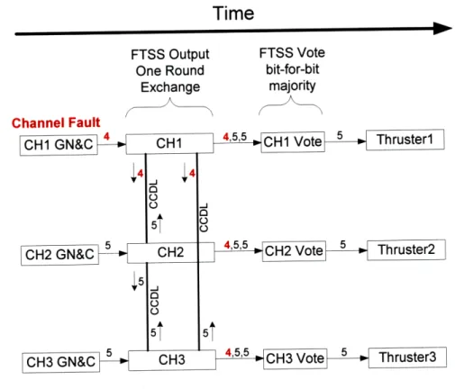
The FCP then executes the flight critical GN&C code which uses the sensor values to compute actuator commands. The FCP then sends a request to the NE to have the actuator command data voted by the four channels. The NE uses a one round exchange with the other channels. After the vote, each NE placed the voted actuator command in memory accessible by the ICP. The ICP reads the voted command and sends it to the actuators using the appropriate I/O card.
2.4.2.2 Other NMR Examples in Brief
The Boeing C-17 Globemaster is a large military transport aircraft that was designed in the late 1980's and uses a digital fly-by-wire flight control system that is fail-op, fail-fail-op, fail-passive [27]. The probability of aircraft loss due to flight control system failures must be "extremely remote" which is defined as 5 x 10⁻⁷ occurrences per mission for military transports. The fly-by-wire (FBW) system uses a quadruplex NMR design with a channelized data bus (Mil-Std-1553b) topology. The four channels are frame synchronized and exchange data using a CCDL. What is interesting about this design is that fault tolerance and redundancy management functions such as voting are implemented in software.
The Boeing 777 transport aircraft was designed in the early 1990's and uses a digital fly-by-wire flight control system [16, 20]. This system must satisfy FAA reliability requirements for catastrophic failures, namely a 1 x 10⁻⁹ probability per hour or event. The system is certified for CAT IIIb automatic landings (see Appendix D). The FBW system uses a TMR design that includes three flight control computers that are connected to three ARINC 629 data buses. The system uses a global data bus architecture where sensors are connected to all three channels.