HAL Id: tel-01674170
https://tel.archives-ouvertes.fr/tel-01674170
Submitted on 2 Jan 2018HAL is a multi-disciplinary open access archive for the deposit and dissemination of sci-entific research documents, whether they are pub-lished or not. The documents may come from teaching and research institutions in France or abroad, or from public or private research centers.
L’archive ouverte pluridisciplinaire HAL, est destinée au dépôt et à la diffusion de documents scientifiques de niveau recherche, publiés ou non, émanant des établissements d’enseignement et de recherche français ou étrangers, des laboratoires publics ou privés.
home energy management system
Trung Kien Nguyen
To cite this version:
Trung Kien Nguyen. Design and soc implementation of a low cost smart home energy management system. Other. Université Nice Sophia Antipolis, 2015. English. �NNT : 2015NICE4127�. �tel-01674170�
UNIVERSITÉ NICE SOPHIA ANTIPOLIS
POLYTECH’NICE-SOPHIA
École Doctorale des Sciences et Technologies de
l’Information et de la Communication
Electronique pour Objets Connectés
THESE
Pour obtenir le titre de
Docteur en Sciences spécialité Electronique
de l’Université Nice Sophia Antipolis présentée et soutenue par
Kien Trung NGUYEN
Conception et réalisation d’un système de gestion intelligente de la
consommation électrique domestique
Thèse dirigée par Gilles JACQUEMOD Soutenance prévue le 11 Décembre 2015
Jury :
P. GARDA Rapporteur Professeur, Université Pierre et Marie Curie Paris S. WEBER Rapporteur Professeur, Université de Lorraine Nancy
G. JACQUEMOD Directeur Professeur, UNS Sophia Antipolis
E. DEKNEUVEL Co-Encadrant Maître de Conférences, UNS Sophia Antipolis L. HEBRARD Examinateur Professeur, Université de Strasbourg
B. NICOLLE Examinateur Ingénieur, Qualisteo Nice
Table of Contents
Chapter 1. INTRODUCTION ... 1
1.1. Motivation ... 3
1.2. NIALM Technology and Applications ... 5
1.2.1 Introduction ... 5
1.2.2. State of the art ... 6
1.2.3. Applications of NIALM ... 9
1.3. Electrical Signatures ... 10
1.3.1. Parallel RLC model ... 11
1.3.2. Steady-state signatures ... 12
1.3.3. Transition-state signatures ... 14
1.4. The trend of NIALM technology ... 15
1.5. Thesis contributions ... 17
1.5.1. Context ... 17
1.5.2. A real-time innovative NIALM proposal ... 17
1.5.3. A HW SW co-development methodology for rapid prototype ... 18
1.6. Thesis Organization ... 19
Chapter 2. SYSTEM MODELING FOR EMBEDDED SYSTEM ... 21
2.1. SoC, SoPC and FPGA ... 23
2.2. System development of SoC ... 25
2.2.1. Algorithm optimization ... 25
2.2.2. SoC design flow ... 27
2.2.3. SoC development approaches ... 29
2.3. Model of Computation ... 35
2.3.1. Finite State Machine ... 36
2.3.2. StateChart ... 38
2.3.3. Dataflow modeling ... 40
2.3.4. Kahn Process Network ... 41
2.3.5. Synchronous Data Flow ... 42
2.3.6. Structured Data Flow ... 44
2.4.1. System design tools ... 47
2.4.2. Model-based design tools ... 48
2.4.3. Architecture design tools ... 51
2.4.4. RTL design tools ... 54
2.5. HW SW codevelopment approach for rapid prototyping ... 56
2.5.1. Modeling executable specification of RPN system ... 59
2.5.2. Architecture exploration ... 64
2.5.3. Hardware Software co-development ... 66
2.6. Conclusion ... 67
Chapter 3. APPLICATION MODEL FOR A REAL-TIME NIALM SYSTEM ... 69
3.1. Activity model of system in dataflow ... 71
3.1.1. System requirements ... 71
3.1.2. Entity analysis and modeling ... 72
3.1.3. Activity model of system ... 73
3.2. Electrical signatures extraction: Event-based approach ... 76
3.2.1. Power signatures ... 78
3.2.2. Shape of transitions signatures ... 85
3.2.3. Harmonic signatures ... 86
3.2.4. Early application classification ... 89
3.3. CUSUM - An online Event Detection ... 91
3.4. Genetic Algorithm-based power Disaggregation ... 96
3.4.1 Sequential clustering K-mean ... 98
3.4.2. Genetic Algorithm ... 99
3.5. Conclusion ... 101
Chapter 4. SOC IMPLEMENTATION OF NIALM SYSTEM ... 103
4.1. The Zynq-7000 platform ... 105
4.2. Executable specification ... 107
4.2.1. Modeling Virtual Appliances ... 107
4.2.2. Modeling the NIALM process ... 108
4.2.3. Modeling Control Logic ... 110
4.4. Architecture exploration ... 116
4.5. Prototyping system ... 119
4.6. Conclusion ... 122
Conclusions and Perspectives ... 123
Conclusion ... 123
Perspectives ... 125
Publications ... 123
Acronyms, abbreviations and definitions
Term Description
ADC Analog to Digital Converter AMS Analog Mixed Signal
API Application Program Interface
ASIC Application Specific Integrated Circuit CLIP Component-Level IP
CPU Control Process Unit CUSUM CUmulative SUM DFD Data-Flow Diagram DMA Direct Memory Access DSP Digital Signal Processing EPC Energy Performance Certificate FIR Finite Impulse Response FFT Fast Fourier Transform FIFO First In, First Out
FPGA Field Programming Gate Array FSM Finite State Machine
GA Genetic Algorithm GUI Graphical User Interface HDL Hardware Description Language HLS High Level Synthesis
HMM Hidden Markov Model HW SW HardWare SoftWare
HVAC Heating, Ventilation and Air Conditioning HID High Intensity Discharge
IIR Infinite Impulse Response IP Intellectual Properties KPN Kahn Process Network LUT Look Up Table MCU Micro Controller Unit MoC Model of Computation
NIALM Non-Intrusive Appliance Load Monitoring NoC Network on Chip
OCED Organization for Economic Cooperation and Development OVP Open Virtual Platform
PRA Pyramid Recursive Algorithm
REDD Reference Energy Disaggregation Data set RMS Root Mean Square
RPN Reactive Process Network RTL Register-Transfer Level SDF Synchronous Dataflow SoC System on Chip
THD Total Harmonic Distortion TLM Transaction-Level Model UML Unified Modeling Language USOM USer Operating Mode VAR Volt-Ampere Reactive VFD Variable Frequency Driver
VLSI Very Large Scale Integration circuits XSG Xilinx System Generator
1
C
HAPTER1.
INTRODUCTION
Contents
1.1. Motivation
1.2. NIALM technology and Applications
1.2.1. Introduction 1.2.2. State of the art
1.2.3. Applications of NIALM
1.3. Electrical signatures
1.3.1. Parallel RLC model 1.3.2. Steady-state signatures 1.3.3. Transition-state signature
1.4. The trend of NIALM technology 1.5. Thesis contributions
1.5.1. Context
1.5.2. A real-time innovative NIALM proposal
1.5.3. A HW SW co-development methodology for rapid prototype
1.6.Thesis organization
Abstract:
This chapter is the useful background information of the Non-Intrusive Appliance Load Monitoring (NIALM) technology and the motivation of this research. Section 1.1 presents a big image about the relation between energy usage of human and environmental pollution. This section also talks about smart meters, which can monitor and give people more information about their energy usage to engage them in saving energy. Section 1.2 gives a brief introduction about the NIALM technology, a state of the art, and its daily area in life. Section 1.3 introduces some electrical signatures, which a NIALM system must extract, analyze to recognize and monitor power usage of appliances in an electrical network. Section 1.4 discusses about the trend of NIALM technology to be able to solve its remain challenges. Thus, section 1.5 presents our proposal for an innovative real-time NIALM system based on System on Chip (SoC) and the contributions of this thesis. Finally, section 1.6 will present the organization of this thesis.
3
1.1. Motivation
We are today's fully aware of the global climate change, the global warming mainly coming from the carbon dioxide (CO2) emission through the urbanization of human. Too much CO2
causes natural disasters such as drought, flooding, tsunami, hurricane, diseases that destroy the earth and human life. Even though more and more developed countries have planned to use green technologies, renewable energy sources and better energy usage monitoring, most of developing countries accept air pollution for economic reasons. In Figure 1.1, the CO2 emission
in fossil fuel energy almost remains from 1990 to now in Organization for Economic Cooperation and Development (OCED) countries. However, this value increases three times in non-OCED countries and mainly in coal. The annual energy outlook 2013 of US Energy Information Administration [1] also shows that from 2010 to 2040, coal-fired power plants are still generating about 40% global electrical power and emit over 40% of CO2 in the earth and
these CO2 emissions are still mainly linked to the use of energy of human. The amount of CO2
emission are also shown in the greenhouse gas equivalencies calculator tool of the Environmental Protection Agency of United States [2] that 15.873 MWh electricity consumption – the average energy usage in house for one year, is equivalent up to 10 tons CO2
emission to the environment. Consequently, changing people’s awareness of using energy effectively and economically becomes very urgent.
Billion metric tons Billion metric tons
(a) (b)
2013
Figure 1.1 (a) World energy-related carbon dioxide emissions by fuel type, (b) OECD and non-OECD energy-related carbon dioxide emissions by fuel type [1]
Although European (EU) countries are leading in using renewable energy sources. Their objective aims to replace 20% of EU’s energy consumption by using renewable energy sources in 2020 [3]. Thus, economic energy usage management is still vital in many decades and people want to decrease environmental pollution. In 2007, England introduced the Energy Performance Certificate (EPC), which contains the rating of energy efficiency of a house and recommendations for potential improvements. As illustrated in Figure 1.2, the EPC gives customersthe energy consumption level of the house and the potential future saving money, if
4
they follow such recommendations. With better information in monthly electricity bills, the EPC can engage people to reduce the energy usage in the house.
(a) (b)
Figure 1.2 Some information in an EPC sample [4]
However, EPC has impact on only 18% of people and 17% of people follow its recommendations [4]. It is probably due to the recommendations are too general which recommend them to repair the house or to replace better appliances. They are not convenient for most of the customers who just need to know the relation between the increasing on the electrical bills and their daily or weekly activities. That is why smart meters, the emerging technology to help people to know their monthly energy consumption, are gradually replacing mechanical power meters nowadays. Some new modern smart meters even offer real-time feedback on the in-home display with detailed daily records of activities of customers in appliances and their effect on the total energy consumption as well as the ratio of energy usage in individual appliance. This individual appliance-monitoring feature at the heart of those smart meters gives customersmany advanced benefits:
- Real-time feedback about the effect of their behavior in energy consumption. For example, the water heater is, sometimes, still turned-on while no one is taking a bath or the air conditioning in the living room is still turned-on while there is no one there. - Awareness of energy performance of their appliance in comparison to the standard
energy-saving products. Some customerswill recognize that after three years, they have to pay the same money (including buying cost and yearly bills) for the new modern
5
energy-saving refrigerator and the old one while it is certain that using a new modern refrigerator is much more comfortable and convenient.
- Suggestions about energy usage based on the Time-of-Day Electricity Pricing. Consumerswill be indicated about variations of electricity prices during a day, and they can then keep using the same amount of energy while saving money by using it at the right time.
- Estimating the equivalent CO2 emission of energy consumption can engage consumers
in changing their energy usage behaviors for environmental protection.
1.2. NIALM Technology and Applications
1.2.1 Introduction
There are two solutions for monitor consumption on individual appliances: using one sensor per appliance as in a conventional approach or using only one sensor to monitor the whole loads as in the Non-Intrusive Appliance Load Monitoring (NIALM) approach. Intrusive sensors work similarly to a normal current meter that needs to be connected in serial with the load to measure its current. In contrast, non-intrusive current sensors can convert the magnetic field around the electrical wire into analog voltages without intrusive connections. Such sensors are more advanced than intrusive sensors because of a very fast, safety and flexible installation.
As illustrated in
Figure 1.3, NIALM technology introduced by Hart in 1992 [5] aims to use only one non-intrusive sensor to monitor all appliances in the electrical network. Because of using fewer hardware components, NIALM has lower cost because it is easier to setup and maintenance than conventional method. Unfortunately, NIALM requires more complex algorithms to analysis, classify, breakdown and assign power consumption to appropriate appliances while intrusive method is able to define exactly from where the power usage events come. However, intrusive method will be very expensive and it has to use complex communication network to transfer data that limits the bandwidth if there are too many nodes in the network. NIALM method, which has only one node, can use full bandwidth of communication channel. The limited number of appliances, which can be detected and monitored, depends only to the efficiency of NIALM algorithms. Some NIALMs can also do many computations at sensing nodes for examples computing power consumption, detecting transitions to decrease data size in communication channels.
6 Data acquisition Preprocessing Event Detection Classification Estimation Conventional method
Load 1 Load 2 Load n
NIALM method
Break down
Main power line
Figure 1.3 Conventional and NIALM method in power monitoring application
In order to be able to monitor consumption on individual appliances in an electrical network using only one sensing node, NIALM systems must have five basic processes:
- Data acquisition: NIALM system collects values from current and voltage sensors in a defined sampling frequency.
- Preprocessing: This is an important step to handle in noise filtering and electrical features extracting such as total real power, re-active power and apparent power. It can contain some advanced tasks such as calculating the phase of electrical signal, harmonics data and power factor. More electrical features the processing extracts, more accuracy the step classification is.
- Event Detection works on the change detection in aggregated current or power to detect an ON-turning or OFF-turning from an appliance in the electrical network. This step also extracts the transition signatures after a detected event.
- Classification clusters events after Event Detection step and matches ON events to OFF events to classify appliances.
- Estimation is the last process to summarize the total power consumption and ratios power consumption in each appliance.
1.2.2. State of the art
In 1992, Hart [5] introduced the topic NIALM which can monitor a number of switches ON and OFF from appliances. His algorithms based on 1-second sampling average power and Root Mean Square (RMS) voltage was able to compute the normalized real and reactive power. The normalized powers were used by the edge detection algorithm to find out the time of the change in normalized power. A fixed 15 Watts tolerance was used to define steady periods and transition periods to create the time-stamped step-change p-vectors. These p-vectors are clustered to find out the quantity of clusters and their centroids to be able to pair the ON-OFF or Finite State Machine (FSM for multi-state appliances) models of appliance using the rule Zero Loop-Sum
7
Constraint. Last function is to set the name of the model of appliance for the system able to track out in the future. However, his algorithm has still need to be improved to work well with under 100 W appliance, continuously variables, and multi-state appliances. Moreover, it cannot distinguish appliances who have the similar real power and reactive power.
Leeb et al. 1995 [6] used higher sampling frequency to extract power information of third harmonic for classification. Leeb also used three sampling rate levels to detect both fast, medium and slow transitions. However, the classification cannot process in real-time and both overlapped transitions and continuous variable appliances are still intractable. Three sampling rate levels in detection are not enough for all appliances in commercial and industrial application so that Laughman [7] proposed the use of shape information to detect transitions. However, his system is complex and needs a tedious training with all kinds of appliance that it should be able to work with; and his method can still not trace overlapped events.
Baranski et al. in 2004 [8] presented a new approach for NIALM system. His algorithm also uses power data sampled in 1-second rate to detect events by considering the change between two sequential active powers with a threshold value and the direction of the change. That means two changes in the same increasing direction belong to the same event. Then, he used Fuzzy-clustering algorithm to cluster all the detected events. His paper clearly presents Genetic Algorithm (GA) to find out both ON-OFF and FSM appliances up to five different states. However, his algorithm limits the length of detected event sequence to be processed in the limitation in maximum process time.
Instead of using both current sensors and voltage sensors in standard NIALM system, Cox et al. proposed, in 2006 [9], a NIALM system to identify the operation appliances using only the distortion information of total voltage. Removing the need of a current sensor gives a more economical NIALM system solution. The preprocessor will estimate the coefficients information of the input voltage in some order harmonics. Then software will analyze each array of spectral envelopes to detect the transitions. Cox said that system now could detect and identify ON-OFF appliances with small power consumption from 50W. Moreover, his result also shows the ability to track the FSM type appliances. Although his work does not use power measurement, tracking the appliance using only voltage sensor can cooperate with all kind of current power meter to give more energy consumption information for customer in the electricity bill. However, Cox needs to evaluate the accuracy of his system in all household appliances.
Suzuki et al. in 2008 [10] used integer programming approach, based on current waveform in one period, to classify appliance, then to disaggregate appliances. No complex preprocessing algorithms and steady based NIALM are advantages of his algorithm. This algorithm also works with FSM appliances, which makes one more integer equation for each appliance. However, it needs to have a database of appliance waveform and quite sensitive with unknown noises.
Patel et al. in 2009 [11] and Froehlich et al. in 2010 [12] used only single plug-in sensor to detect events of some home appliances from electrical noise in power line in operation of appliances. They found that there are transition noises and continuous noises. The transition
8
noise lasts only some microseconds and comes from switching mechanism and load characteristics of appliances while continuous noises come from the internal switching mechanism. He developed the power-line interface hardware to filter and collect a standard 60 Hz AC power signal, 100 to 100 kHz filtered signals and 50 kHz to 100 MHz filtered signals. After that, a USB oscilloscope interface (EBest 2000) was used to amplify signals, convert them to digital data, and send data to a computer in sampling frequency up to 100 MHz. One shifting window FFT algorithm will extract harmonic information for classification using Support Vector Machine (SVM) algorithm. However, his work focuses only on the domestic environment especially with a weak noisy outside environment. Other limit of their works is the dependence of noises onto length and type of electrical wires so that the training databases for the same appliances in different houses are different. Moreover, this method cannot be used in real-time with complex Digital Signal Processing (DSP) card, computer and pre-trained database. The system has not been tested for slow transitions and continuously variable appliances.
Many current researches [13] [14] focused on exploring new disaggregation algorithm on 1 second sampling aggregated power consumption using algorithm Hidden Markov Model (HMM). HMM algorithm based NIALM is developed to work with most of current power meters and quite high accuracy. However, slow sampling rate can cause losing the “peak” states sometimes, which can be an important signature to distinguish same power appliances. Moreover, training phases can meet problem if there are new appliances, which do not exist, in the pre-trained database.
The main objective of most of current research in NIALM is to improve the accuracy of this technology by exploring more complicate disaggregation algorithm. However, such algorithms need a powerful computer such as a server to process. Most of researches also use supervised learning or well-known database to classify appliances. Therefore, some challenges are still valid to solve in NIALM are:
- The need to extract more electrical signatures to distinguish similarity appliances. - The problem of variable load appliances which creates slow transition that is not detected
by most of event detect algorithms.
- A low sampling frequency data can meet problems with overlap transitions and can lead to missing event.
- There are still not any effective methods to detect multi-state load appliances, which can have many states in their operation.
- The NIALM system should be low cost, compact and similar price as current power meter. The low cost system can help NIALM to gain popularity in every home in the finance support program of the electricity company or the government.
9
1.2.3. Applications of NIALM Energy monitoring
People applied NIALM technology in many fields of the life. The first application of NIALM is home or building energy monitoring. Mario E. Berges et al. 2010 [15] discussed about four types of existing commercial NIALM products: the whole-house meter, the smart meter ARM/AMI, the plug-load meters and the smart home packaged solution. Products of TED company with the Energy Detective Footprints software can track only five home appliances after training their power consumption [16]. Products of Enetics company in USA record over Internet detail information of energy usage such as time, current, voltage, power, power factor, Total Harmonic Distortion (THD) [17]. Then they provide energy usage analysis based on this information in both residential and industrial sites but their system does not provide real-time monitoring feature.
Gas and water monitoring
Gas and water monitoring is another application of NIALM which is often integrated to power monitoring activity to give customer a complete energy monitoring. In an extra part of the article [12] in 2010, Jon Froehlich et al. applied a single point sensor approach to develop HydroSense system to monitor water usage and the GasSense system to monitor gas usage in house. There are already real products to monitor gas usage in at home for example Loop Gas product of Navetas company in UK [18].
System fault detection and maintenance
System fault detection and maintenance may be the most interesting capability of NIALM technology. The research [19] used NIALM technology to develop a Condition Base Maintenance system in a US Navy Ship in 2005. Because of the difficulty to connect sensors for all the electrical devices in an exist system in the ship, NIALM was used to trace out and monitor the operation of all devices in the system in order to detect and to predict failures in their working. This application is very useful when analyzing all components inside a complex machine is a very hard work. Moreover, we can also apply this capability to home energy monitoring to early detect errors in electrical appliances for the maintenance.
Commercial and Industrial domain
However, most researches in the past worked in residential site and there are not adequate researches about using NIALM in commercial and industrial sites. Most of commercial NIALM products are applying in home energy monitoring. The lack of applying NIALM in commercial and industrial sites may come from below reasons. First, in commercial and industrial sites, machine can contains many basic electrical appliances inside so that it is very difficult to recognize what real machines are working. For instance: an industrial oven can contain a magnetron tube that generates heat in di-electric heater type, one or more fans, power controller and time controller, lamps, tri-ac driver circuit and high voltage transformer. Second, many
10
kinds of noise in industrial site coming from high power motors, fans or inverters can generate errors in current detection algorithm of NIALM. Third, monitoring all basic appliances inside machine in commercial and industrial sites is very difficult so that it takes a lot of time and money to build database for all new coming machines. A NIALM system may be impossible to analyze and disaggregate all electrical machines in an industrial factory or one NIALM system cannot monitor all apartments in a big building. However, in the supporting of other technology for example wireless sensor network, which each NIALM system is a monitoring node, this technology can be used more broadly in commercial and industrial site.
1.3. Electrical Signatures
Electrical signatures are characteristic information of electrical appliances such as current, power, power factor, harmonic etc., which can be used to distinguish appliances. As illustrated in Figure 1.4, such signatures can be classified into two main categories that affects the event detection and algorithms in NIALM: Steady-state signatures and Transition-state signatures. Steady-state signatures are steady-features, which can be derived under the steady-state operation of the appliances, or in other words, steady-state signatures are the changes in interested features in electrical network after ON-turning and OFF-turning occurrences. In contrast, a transition-state is the duration between two steady states. The differences in structures between appliances cause differences in some electrical features in transitions-state that can be used to classify them.
Figure 1.4 Electrical signatures for classification
Electric signatures Transient signatures Shape Duration Size Voltage noise (EMI) Steady signatures Harmonic currents Fundamental frequency Power Current Power factor Voltage Noise (EMI)
11
1.3.1. Parallel RLC model
Before analyzing in detail about the steady states and transition states, we present the theory of RLC architecture of electrical appliances, which can explain the difference in electrical signatures between appliances. In theory, an electrical circuit composed by basic elements resistor R, inductor L and capacitor C can represent appliances. Then, this circuit can be simplified to an equivalent parallel RLC circuit as illustrated in Figure 1.5. In this model, power information of appliance then can be computed by traditional equations. VS, the root mean
square (rms) of AC voltage, are often used to express voltage of electrical network connected to the RLC circuit. Three elements R, L, C of the circuit generate three kinds of power consumption. In this circuit, IR, IL, IC are currents flowing in R, L and C branch; and IS is the
total current in parallel RLC circuit.
Figure 1.5 Parallel RLC model of an appliance
Real Power P, measured in Watt, is a function of circuit’s dissipative element resistance R. 𝑃 = 𝑉𝑠. 𝐼𝑅 (1.1)
Reactive power Q, measured in Volt-Ampere-Reactive (VAR), is a function of circuit’s reactance X.
𝑄 = |𝑉𝑠. 𝐼𝐿 − 𝑉𝑠. 𝐼𝐶 | = |𝑄𝐿− 𝑄𝐶| (1.2)
Apparent power S measured in Volt-Ampere (VA) is a function of circuit total impedance.
𝑆 = 𝑉𝑠. 𝐼𝑆 (1.3)
Applying the Kirchhoff’s current law in RLC parallel circuit, we notice that currents in each branch of the circuit are not in the same phase as illustrated in Figure 1.5. Current flowing in resistor R branch is in same phase with voltage. However, current flowing in inductor L branch is later 90 degrees than the voltage and current flowing in capacitor C branch is earlier 90 degrees than the voltage. Apply the Pythagoras’s theorem; we have the equation to compute aggregated current.
12 Replace (1.4) to (1.3), we get 𝑆 = 𝑉𝑠. 𝐼𝑆 = 𝑉𝑠. √𝐼𝑅2+ (𝐼 𝐿− 𝐼𝐶)2 2 = √𝑉 𝑠2𝐼𝑅2 + 𝑉𝑠2(𝐼𝐿− 𝐼𝐶)2 2 Or 𝑆 = √𝑃2 2+ 𝑄2 (1.5)
When a new electrical appliance is turned on, its represented RLC circuit is connected to the electrical network to create a new circuit in the electrical network, which contains new parallel RnLnCn electrical circuit with new power information Qn, Pn, Sn as illustrated in Figure 1.6. Based on the relation between represented RLC of the new electrical appliance with differences in power Qn, Pn, Sn from the point (P0, Q0) of working appliance 1, there are six types of event
with three turning on events and three turning off events as illustrated in Figure 1.6. Moreover, events ON can be matched with events OFF in five pairs: 1, OFF-2), 1, OFF-5), (ON-3, OFF-2), (ON-(ON-3, OFF-5) for electrical appliances that have XLn smaller than XCn, and pair
(ON-6, OFF-4) for electrical appliances that have XLn larger than XCn.
Figure 1.6 (a) Parallel RLC model of electrical network after turning on the second appliance; (b) Six types of appliance based on power change dS, dP, dQ = dQL - dQC
1.3.2. Steady-state signatures Power change
Most common examples of steady state signatures are the changes of real power (ΔP) and reactive power (ΔQ) after a changing status in appliance. Some appliances having only two
13
states ON and OFF are called ON-OFF appliances. Some other appliances having many states in their operation are called multi-state appliances or finite-state appliances. As shown in Figure 1.7, the difficulty in classifying finite-state appliances is that such appliance can work as either an ON-OFF appliance or a multi-state appliance depending on its operation mode. Another complex finite-state appliance example is a fan with three levels of the speed forms a 4-states appliance. However, this appliance has many complete operation modes by many different combinations of transition powers.
Figure 1.7 (a) ON-OFF appliance water pump and (b) 3-states appliance water boiler
Figure 1.8 ΔP-ΔQ plan of some house appliances
Some NIALM algorithms only need the change in real power to disaggregate total power and classify appliance. Parson et al. [13] and Kolter et al. [14] used only the real power changes to classify appliance using the statistic HMM algorithm. Baranski et al. [8] proposed using Genetic Algorithm (GA) for pattern detection based on a series of real power in 1-second time resolution. His method can also work on finite-state appliances. However, only real power method is not
14
enough to distinguish appliances that have the similar real power. In order to solve this problem, many researches [6] [7] used both real power and reactive power in ΔP-ΔQ plan to classify appliances. Figure 1.8 shows the principle of this approach. In order to enhance the NIALM accuracy, Leeb et al. 1995 [6] proposed using power information in third harmonics to enhance the accuracy of appliance classification. C. Laughman et al. [7] even proposed using ΔP-ΔQ plan of up to seventh harmonic to distinguish loads.
Current and voltage
Waveform of current has been used as a steady-state electrical signature. In a research in 2004, Lee, W. et al. [20] explored that current waveforms are different between appliances and they can be used for classifying appliance. Moreover, Suzuki, Kosuke, et al. [10] used current waveform to disaggregate power base on integer programming method. First, they collected a period current waveform of many appliances including their operation modes. Next, overall load circuit is represented by a current waveform (in 1 period) which is the total of all current waveform of working appliances and a disturbance value generated by noise or unknown appliance. Finally, an integer quadratic programming problem is solved to estimate the working appliances, which minimizes the disturbance value. Cox, Robert et al. [9] used only voltage measurement in high frequency to classify appliance. Ting, K. et al. [21] also proposed using 2-dimensional voltage-current trajectories under start up and steady-state condition to distinguish appliances.
Many NIALM researches worked on voltage noises in very high frequency [11], [12], [22]. These steady-state signatures are potentially the most useful information to classify appliances accurately. That can solve the problem similarity in power based NIALM approaches. However, this approach needs expensive hardware, which is able to extract small signal in high order harmonics. Moreover, voltage noises caused by appliance are very small and easy to be interfered by noises from environment.
1.3.3. Transition-state signatures
Transition state signatures are another type of electrical features extracted from electrical network. Most of transition signatures occur in a very short instant (milliseconds) or in high order harmonics. Such signatures are more difficult to be extracted than steady state signatures because measuring them requires high frequency data sampling in acquisition hardware. However, they add more supplement information to classify more appliances.
Shape of transitions
Some examples of transition-state signatures are start-up current and power transients with features current spikes, size, duration, shape of the transitions. Wang et al. in 2012 [23] decomposed power consumption to two basic shapes triangle and rectangular. These basic
15
shapes then can be represented by data such as start-time, peak-time, peak value, steady-time and steady power in a two graphic units, which is call a schematic diagram.
Voltage noises
Patel et al. [11] developed a device to measure electrical voltage noises in high frequency sampling in both steady and transition states. Their research shows that electrical noises in transition state have rich frequency spectrum varying from 10 Hz to 100 kHz as illustrated in Figure 1.9. This frequency spectrum depends not only on the load characteristic but also depends on the mechanic architecture of the switches, and the length of electrical lines. Therefore, this is also a potential approach to distinguish same kind appliance located in different rooms. Moreover, this noise can be measured from any electrical outlets at home.
Figure 1.9 (a) Transient voltage noise signatures of turning ON event of a light switch, (b) Steady-state continuous voltage noise signatures of some home appliances [11]
1.4. The trend of NIALM technology
The revolution of electronics and telecommunications is changing the application and the architecture of NIALM system. In this section, we will discuss about some important technologies and their impacts on the NIALM then figure out the perspectives of future NIALM smart meters
Ubiquitous computing (ubicomp)
This concept means that computing can appear anywhere in human life in any devices, any format. Some involved technologies are Internet of Thing (IoT) and Wireless Sensor Network (WSN). Ubicomp can have underlying technology sensors, microprocessor, network, user interface etc. An example of ubicomp is the LG Smart ThinQ LFX31995ST Refrigerator [24], which can monitor its performance, energy consumption, weather and track the food freshness, daily receipt and notes. When all home appliances support ubicomp technology, they can record their power consumption and customer behavior by them-selves. NIALM can be applied there to disaggregate power consumption of all electrical devices inside that appliance for monitoring
16
and maintenance purposes for example the pumps, lights and fans inside the smart refrigerator. Information about their power consumption and the temperature inside the refrigerator can give us health status of the refrigerator. So that, for the smart appliance like that, a small stand-alone low cost NIALM meter is more reasonable than the expensive NIALM system.
Cloud computing
Cloud computing technology has been applied into many commercial smart products.
Instead of using a computer to process the complex applications and store database, cloud-computing devices can send data to be processed and to be stored in the server. This technology helps the service supplier to upgrade and maintain the system much more easily and more economically. Unfortunately, in NIALM domain, storing power consumption data for millions houses for months or a year is not practical so that current smart meters only send very slow sampling rate aggregated power consumption to reduce the size of transmitted data. This limits the capacity of NIALM to disaggregate more appliances. The reasonable solution is that future NIALM meter can do the preprocessing and event detecting by themselves to extract more electrical signatures with time-stamped events. Then cloud computing is applied to let the server disaggregates total power using event data and do other utility services such as creating detail electricity bill, data statistic.
System on Chip (SoC)
The last recommended technology for the future of NIALM is System on Chip (SoC). This is single special integrated circuit, which is embedded inside all components to be able to run as a computer. SoC now may contain not only memory, processor unit, input output interface, timing sources, power manager unit; but also communication interface units such as USB, Ethernet, UART, SPI, Wi-Fi module, and real world interface such as temperature sensor, Analog to Digital converter, GPS etc. Some new SoCs also have special reprogrammable hardware named Field Programming Gate Array (FPGA). System on Programmable Chip (SoPC), which can be constructed to complex custom Digital Signal Processing (DSP) hardware to accelerate the computing for instance Zynq-7000 family of Xilinx [25]. Such a SoC includes a Processing System part and a Programmable Logic part. Processing system part includes dual-core ARM Cortex A9 with cache, memory, communication interfaces etc. Programmable Logic FPGA is programmed by using Hardware Programming Language (HDL). HDL is the special language to create the electronic circuit inside FPGA such as a filter, a microprocessor, a video processing hardware unit etc. Therefore, SoC is potential real future for NIALM and all algorithms can be implemented inside a chip. While the microprocessor processes the simple function, the hardware part (FPGA or DSP) will handle and accelerate the hard constraint and complex algorithms. SoC is also used to name the methodology that develops hardware and software in parallel in a system.
17
1.5. Thesis contributions
1.5.1. Context
This research belongs to the CoCoE project (Contrôle de la Consommation Electrique dans les bâtiments) of ARCSIS (Pôle de compétitivité Solutions Communicantes Sécurisées) and CIM-PACA Design Platform. Partners of this project are EpOC (URE UNS 006) and IM2NP (UMR AMU 7234) laboratories, Qualisteo and RivieraWaves companies. The objective of this project is to develop an innovative, non-intrusive and communicating solution for electrical energy measurement in the building. Today, optimizing energy in building is based on the total electrical power consumption, with no detailed information about power consumed in individual appliances. Thus, solution so far needs complex systems with many meter and sensors, which is incompatible and inconvenient with existing building.
The problematics, which must be solved by the CoCoE project, are that the electric power consumption information is less accessible, not in real-time without any information about kind of appliances and usage, even with the Linky future smart meter. This can be solved by using NIALM technology implemented into FPGA and with the development of remote wireless sensors. There are two other PhD students working on this project in developing these new sensors to measure electrical current and other electrical signatures (Cifre thesis with Qualisteo company) and modeling and optimizing wireless communication systems (Cifre thesis with RivieraWaves company). The CoCoE project received an award during the World Efficiency Congress (Paris, October 2015): “Lauréat du Trophée de la Recherche Publique Energie-Climat-Environnement”, given by ADEME and the two magazines EnergiePlus and Mesures, in the topic of Energy efficiency. Moreover, CoCoE is a building block of the “Smart Campus Nice Sophia Antipolis” project, which has been labialized by the French ministry of economy on the national industrial plan on smart grid.
1.5.2. A real-time innovative NIALM proposal
The thesis proposes a development of an innovative NIALM system based on SoC, which can solve some challenges in electrical power measurement and optimization. The performance of system was analyzed and validated according to the NIALM public data set REDD (http://redd.csail.mit.edu) to prove that they can solve well above technical challenges in NIALM technology. The system can enhances the precision or accuracy of the energy estimation to reach more than 80% of classification of the total power by solving several challenges including:
Extraction of more electrical signatures to improve distinguishing similar appliances. They are changes in real power, reactive power and Total Harmonic Distortion (THD)
18
of current as well as the shape information of transitions including maximum and minimum values of real and reactive power in the transition and the duration of the transition.
Detection of slow transitions in variable load appliances. Detection of simultaneous transitions to avoid missing event
Detection of multi-state load appliances, which can have many states in their operation. Moreover, attempting to solve these challenges requires carefully examination of the timing constraints of the system because we have mentioned the possibility for the user to get a real-time feedback of the effect of his behavior. Typical timing constraints are 5 seconds maximum response time or maximum delay between a real event and its display in the Graphical User Interface (GUI) and 200 milliseconds minimum duration between the detection of two events. Apart of performance constraints, technological and economic constraints cannot be ignored. To get a stand-alone, low cost, compact system, the implementation (hardware platform design) must also cope with other constraints including a low cost (more or less than $150), a low power consumption (more or less than 80 Watt), the ability to disaggregate 80% total power consumption and dimensions compatibles to fit on the breaker panel. Regarding of these constraints, SoC technology is a good candidate to solve that big challenge, except that hardware and software system design in SoC is not an easy task to be achieved.
1.5.3. A HW SW co-development methodology for rapid prototype
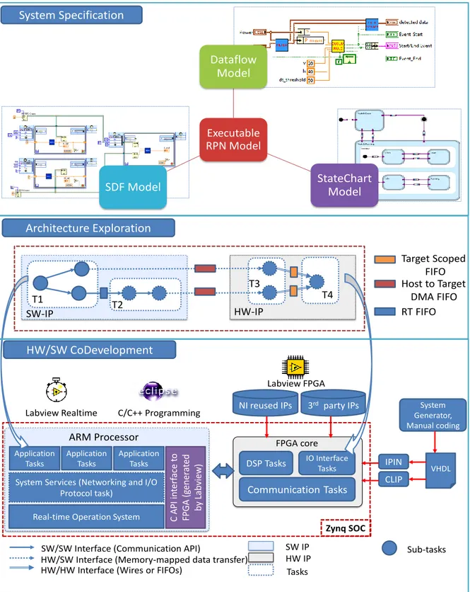
The second important contribution of this research is to propose a hardware-software co-development methodology aiming to develop the ability to rapidly prototype the hard real-time constraint SoC system using LabVIEW FPGA [26]. The thesis will present the use of Synchronous Dataflow (SDF) model as a user case of applying SDF model for hardware software co-development in FPGA SoC. Such approach proves that it is suit in developing a NIALM system and very effective in analyzing the performance in hard real-time constraint system. This model-based SoC design approach uses libraries supported in LabVIEW FPGA in both sides: the rich C, RTOS libraries for software development and the ready National InstrumentsTM reused Intellectual Properties (IPs) for hardware development. Thus, software
and hardware co-developing using LabVIEW is boosted in time from the system design. Moreover, customized FPGA IPs can be developed in several ways: using Xilinx System Generator or HDL manual coding. These IPs then can be integrated to the system by two useful tools: the Component-level IP (CLIP) and the IP Integration Node. These tools are especially vital when supported IP libraries do not satisfy hard constraint functions. Another advantage of this methodology is the possibility proceeding quickly to architecture exploration because partitioning of the functions in hardware or software can be easily investigated. A C/C++ software developer can appreciate the hardware interface API, which is created by the C API Interface tool in the C/C++ Eclipse programming environment, while a LabVIEW developer can use the interface in the LabVIEW environment. Whatever the environment, the SW/SW interface, HW/HW interface, and HW/SW interface mainly affects the memory and latency of
19
the system that can be analyzed in guide of the system constraints. This approach then enables rapid architecture exploration in order to boost the hard real-time constraints satisfaction by the FPGA and the CPU cooperation, reducing the time to market, which is another major constraint for companies.
1.6. Thesis Organization
The thesis has four chapters, which presents in the deep research about the NIALM technology from defining the drawbacks of this technology and their future in the support from the evolution of electronics and telecommunications to propose an innovative NIALM system. In order to develop such a system, the thesis presents base knowledge of embedded system in SoC development methodology, Model of Computation (MoC), and languages and tools. The HW SW co-development methodology to prototype rapidly the NIALM system based on SoC technology is also presented in the document. Then, the thesis also presents the application model for the NIALM meter using many MoCs: the dataflow, synchronous dataflow and statechart model. Finally, results of our experiment work will be presented in the end of the thesis. Detailed contents of each chapter are specified:
Chapter 1 states the motivation of the thesis on engage people in saving electrical power.
We then focus on investigating the NIALM technology- an innovative technology in monitoring power usage on individual appliances in the building. The chapter will present quite deeply about the principle of NIALM approach with their advantages, state of the art of NIALM with remain challenges and predicting the trend of this technology.
Chapter 2 presents about many theories in developing a SoC embedded system. Reader can
also find useful knowledge about the architecture independent design and the model of computations (MoCs). MoC can help developer in finding the best architecture for system early at design step. This capability can increase the productivity, optimize resource, and improve the performance to save cost and time from development to market of product. Introduction about design languages and EDA at each design level of system will be presented at the end of this chapter. This chapter also describes a hardware-software codevelopment approach aiming to rapid prototyping SoC application with hardware acceleration using FPGA. In this approach, we also propose to use synchronous dataflow model to model the system because this model can support well allocating memory and scheduling the operation of system in compilation time in multi processors architectures.
Chapter 3 focuses on the development of algorithms for NIALM application. First, we
present a system specification of innovative NIALM system, which can solve many challenges of NIALM technology in extracting more electrical signatures, detecting multi-states appliance and aiming to the development of real-time NIALM system. Then, information about the Cumulative Sum (CUSUM) event detection and Genetic Algorithm-based disaggregation algorithm will be presented. The chapter also presents some functional verification results in processing a public NIALM data set REDD to analyze the accuracy of system.
20
Chapter 4 presents the use cases of MoC approach and HW/SW system design methodology
in chapter 2 to develop a Real-time NIALM SoC based system, which focuses on analyzing the architecture exploration to satisfy the system requirements. The chapter also presents some detailed experimental prototypes of the system to give us some important conclusions and the road to continue to make a real commercial NIALM product.
21
C
HAPTER2.
SYSTEM
MODELING
FOR
EMBEDDED
SYSTEM
Contents
2.1. SoC, SoPC and FPGA 2.2. System development of SoC
2.2.1. Algorithm optimization 2.2.2. SoC design flow
2.2.3. SoC development approaches 2.2.3.1. Board-based design
2.2.3.2. Virtual platform-based design 2.2.3.3. Model based design
2.3. Model of Computation
2.3.1. Finite State Machine 2.3.2. StateChart
2.3.3. Dataflow modeling 2.3.4. Kahn Process Network 2.3.5. Synchronous Data Flow 2.3.6. Structured Dataflow 2.3.7. Reactive Process Network
2.4. Languages and Development tools
2.4.1. System design tools 2.4.2. Model-based design tools 2.4.3. Architecture design tools 2.4.4. RTL design tools
2.5. HW SW co-development approach for rapid prototyping
2.5.1. Modeling executable specification of RPN system 2.5.2. Architecture exploration
2.5.3. Hardware Software co-development
2.6. Conclusion
Abstract:
Most of complex DSP systems are Reactive Process Network (RPN) systems, which contain both event control processes and data streaming processes. The objective of this chapter is finding out a development methodology to develop a Reactive Process Network system in SoC with FPFA acceleration. Therefore, we investigated various development approaches, many MoCs and development tools. Finally, we proposed new hardware and software co-development approach aiming to rapid prototyping a RPN system.
23
2.1.
SoC, SoPC and FPGA
SoC
Today, SoCs systems contain most of essential elements to be able to develop a complete system just in a single chip: one or many programmable processors, memories (cache, RAM, Flash, DMA), complex buses (processor bus, peripheral bus, communication bus) and many kinds of real world interfaces (temperature sensor, ADC blocks, DAC blocks etc.). Moore’s law is still valid in stating that the number of transistor in a chip doubles every 18 months period. The integrated circuit has passed ultra-large-scale integration with more than 1 million transistors in a tens nanometer technology chip and now turns to the stage of three-dimensional integrated circuit (3D-IC) [27]. Thus, complex SoCs with multi-core processors are used broadly to increase the system performances. Some SoCs may also have special functional units optimized for specific applications such as energy metering integrated HW, audio decoding/encoding, graphic acceleration, and power management unit. However, the higher integration scale the SoCs are, the higher active power the SoCs consume, that makes temperature in SoCs to increase and increases their leakage power.
SoPC
The SoPC concept came from FPGA research domain with the possibility to develop a soft-processor based on the huge programmable hardware elements in FPGA for control applications. Such control applications involve looping and interrupt programming to react to input events that are better processed in software on conventional processor rather than in configurable hardware in FPGA. Thus, two most famous FPGA vendors, Xilinx and Altera, supplied some synthesizable processor cores (soft processor) such as the MicroBlaze of Xilinx and the NIOS of Altera. Moreover, there are also various synthesizable processor cores developed by the community of developers, which may open to be used in any applications and can be found in [28]. However, synthesizable processor cores do not satisfy the requirements in most of products with high performance and low power consumption. Thus, newest FPGAs have integrated real processors (hard processor) core into FPGA for example Xilinx has the Zynq IC with dual core ARM processors embedded into the FPGA platform [25].
SoCs are still developed for some objectives including very high-speed interconnection as network-on-chip (NoC), hundreds or more processors, optical communication interfaces, GPS etc. Integrating FPGA into SoC may be the most important evolution of SoC, which provides developers a powerful tool to develop, and analyze the integration of new specific hardware units to accelerate the performance of their application. This feature of course may not give the best solution to get a system with the highest performance and the lowest power consumption but it can help the company to avoid expensive Nonrecurring Engineering (NRE). NRE relates to the total cost in researching, developing, designing and testing a new product, which may be very expensive because of the large number of iteration during the development cycle. NRE
24
only stops when final product is manufactured and put to market. Unfortunately, NRE in a development of specific applications without standard supported SoCs is still very expensive because some specific hardware IPs are not supported in any current SoCs. Thus, FPGA is necessary to give us a programmable architecture, that supports quickly changes and analyze the customer’s hardware functions before prototyping the product.
Figure 2.1 A generic structure of FPGA
FPGA
FPGA is the lowest cost solution in developing specific customer functions in hardware, which are not supported in current SoCs. Figure 2.1 shows the general structure of a FPGA that has a rich hardware resources as configurable logic blocks (CLB), I/O blocks and programmable interconnects. CLBs contain basic logic cells AND, OR, NOT, Flip-flop which are used to create combinatorial or sequential logic circuits. Modern FPGAs also contain Memory (blocks RAM), DSP blocks and hardware-embedded processors to improve the performance of computations. These resources are surrounded by a dense grid network of programmable interconnects which are controlled by configuration memory in FPGA to connect hardware resources together to create functions in digital circuit. Moreover, the configurable I/O blocks in direction and voltage level of this technology gives developers the flexibility in placing and routing PCB boards.
Because hardware functions in FPGA process much faster than in processor, FPGA functions are often used in specific high performance applications that require very high speed processing. In NIALM system, some complex features must be extracted from electrical appliances in very high sampling frequency: high order harmonics or information of events. The strict timing constraints of such system surely require a high throughput processing that cannot be achieved by conventional microprocessors. Figure 2.2 shows an example where parallel processing in FPGA hardware improves performance 19x compared to a standard DSP processor. That is
25
because DSP processor needs many loops to process an algorithm while FPGA can express in parallel this algorithm in using more hardware resources but improving performance dramatically.
X X X X X
+
Reg
C0 C1 C2 C3 C58
Reg Reg Reg
Data In
Fully Parallel Implementation (Spartan 6 FPGA)
Reg
+
X
Data Out Data Out
Data In Coefficients Sequential (Standard DSP Processor) Single MAC Unit 390 MHz 1 Clock Cycle = 390 MSPS 1,2 GHz 58 Clock Cycles= 20 MSPS
Figure 2.2 Performance comparison between DSP processor and FPGA [29]
The main idea behind FPGA is the ability to program hardware resources using HDL languages. These languages allow developers to program the configuration memory to connect hardware resources in FPGA device together to create a complex digital circuit only by writing codes. Popular HDL languages for “hardware coding” so far are VHDL, VHDL-AMS, Verilog, Verilog-AMS, SystemC, and SystemC-AMS. Moreover, there are also many model-based approaches to develop FPGA functions such as MATLAB HDL coder, Xilinx System Generator in Simulink, LabVIEW FPGA. These languages will be discussed in detail in coming section.
2.2. System development of SoC
2.2.1. Algorithm optimization
In many high-level analysis tools such as MATLAB, Scilab, and Octave, developers can use matrix mathematics, built-in signal processing or graphic libraries to quickly model and analyze algorithms. MATLAB can process a matrix array with memory size up to 8 Gigabytes in 64-bit Window XP running 64-bit MATLAB and this value is up to about 260 MB in Scilab. However, such original algorithms often consume a lot of memory and they do not suit to be implemented into SoCs. In most of DSP systems, developers always have to collect processes, present and analyze data in various formats to get more knowledge about the object. Such complex systems may contain some parts, which have requirements to process and transmit data stream in a very short time. Developers can solve these requirements easily if they select powerful platforms to implement these complex algorithms. However, SoCs do not support well matrix computing on their limited resources so that developers cannot use the same algorithms developed in
26
MATLAB. Developers then need to analyze and select algorithms, which satisfy system requirements in resources usage, power dissipation, latency of each function and global timing constraints.
Figure 2.3 Online algorithm and offline algorithm
Figure 2.3 shows two algorithm types: offline and online algorithms; and processing online algorithm requires less memory and power processor than their offline versions. Thus, online algorithm can be used to optimize both timing and resource usage requirements in SoC system. A following simple example of computing average value in online and offline algorithm is shown below:
%% generate database size = 100000;
data = rand(1,size)*100; %% MATLAB offline code tic(); a1 = data; b1 = mean(a1); t1 = toc(); ---b1 = 50.1136;
Memory size: 800016 bytes
Processing time: t1 = 0.026 seconds
%% MATLAB online code tic(); s = 0; for i =1: size s = s + data(1,i)*100; end b2 = s/size; t2 = toc(); ---b2 = 50.1136
Memory size: 32 bytes
Processing time: t2 = 0.1543 seconds
It shows that memory size usage in online version is only 32 bytes comparison to 800016 bytes in offline version. However, time processing for this online algorithm is about 59 times slower than in offline version when tested on a standard computer. The interesting thing is that
Data package getting Offline version of algorithm Visualize and Analyze algorithm Sequential data getting Online version of algorithm Database of samples Convert Simulation speed M emo ry con su mp tion Offline algorithm Online algorithm
27
this online algorithm needs only 0.1543/100000 or 1.543 microseconds to process each input signal measured in a defined sampling rate about 648 kHz. Such sampling rate is very high in most of SoC applications. Therefore, the main objective of algorithm optimization is to find the compromise algorithms that are able to convert to online version for processing stream data in a resource limited SoC system.
2.2.2. SoC design flow
The design process of a SoC has changed to move from a hardware-oriented perspective to be close to the software-dominated concern in system level design, hardware-software partitioning decision and system architecture design. SoPC technology becomes a powerful tool not just in developing specific hardware functions but also in exploring a system in various architectures (one core, multi core or multi core with FPGA acceleration) to find the best one for the product. So that, this technology may reduce the spin iteration in development works then increasing the productivity and reducing the price of product. Figure 2.4 shows a generic system design flow for SoC with three main steps: system specification, architecture exploration and architecture design.
28
System Specification
System specification is the first step to convert the system requirement of customers to a formal document, which sets a contract between customers and developer about the system to design. This process often starts from requirements defined as an abstract description of customer about general functionality, performance, and budget of the system they want to design. Thus, a system specification must formally exhibit the overall activity of the system and then describes objects, data, events definition, and the functional decomposition with selected algorithms for each function. Although the detailed algorithms may not be described in system specification, some results of algorithm’s analysis should be shown to prove that they satisfy customer’s requirements. Then this document is validated by the end-customer to decide if some modifications in the requirement are needed, involving changes in the functions or improvements in the algorithms. One the agreement from the customer got, system developers can continue their works to develop the system.
Architecture exploration
Architecture exploration is a major step in SoC system level design to decide the final architecture of the system, which includes modeling functionality of system, selecting the best hardware architecture and hardware software partitioning. Partitioning hardware and software will create an abstract platform of the system. This abstract platform should be executable to be able to analyze the input-output relation and to validate the operation and communication between functions with the system specification. From results of this analysis, developer can find out the best architecture for system that can satisfy all required criteria relating to the performance of the system. This selected architecture will be the “golden” abstract architecture to drive the architecture design.
Architecture design
Architecture design contains implementation works: design hardware, software and HW/SW interface in selected architecture from architecture exploration step. In hardware design step, hardware designers have to transform hardware functions from the abstract level model into Register-Transfer Level (RTL) model, which can be synthesizable. Designer can reused hardware IPs supported by SoC vendors to optimize hardware resource and performance or they can use RTL generated by automation generation tools. However, software design is often developed when the design of hardware is completed because just at that time, hardware designers can supply to software designer the API (Application Program Interface) to communicate to the hardware design. In some modern SoC approaches, software and hardware can be developed in parallel if hardware designer and software designer reuse standard communication channels. Architecture design often produces a prototype, on which system designers can validate system in real environment to assure that final products will satisfy constraints enumerated in the system specification.
29
2.2.3. SoC development approaches
Three main SoC development approaches are based-board design, virtual platform-based design, and model-based design approach. However, both three approaches generally contain three main processes: hardware, software and application developments, which are responsible by system, application and implementation designers [31]. In order to handle these tasks, there are many specific requirements for each designer:
- Application designers must have a good knowledge of structures and algorithms of the appliance to be able to decompose it into tasks and sub-tasks. As we mentioned in previous section, application designers are the ones who can investigate various algorithms and do the algorithm optimization to design the best algorithms for SoC system. Therefore, they are often required to have good skills in logistics, mathematics, statistics, and analysis languages such as MATLAB, Scilab, Octave, …
- Implementation designers are hardware designers and software designers who have knowledge of specific platforms and implementation methodologies with software programming languages (e.g. C, C++, C#, Java, Basic) or HDL languages (e.g. Verilog, VHDL, SystemC) or designing platform using CADs tool. They can implement algorithms of application designers in a specific architecture designed by system designers.
- System designers often have a good knowledge of system organizations, architecture of microprocessors, hardware components, and the communication between hardware and software. They can design architectures or platforms for the system by selecting suitable hardware components such as CPU, UART, Ethernet etc. and the interface buses between them and they can design the firmware to handle the communication between hardware and applications. System designers must be able to explore and to analyze the performances of the system in many selected architectures to select the best one, which satisfies all system requirements. In order to do these tasks, system designers must have strong skills in system modeling languages (e.g. Dataflow, Finite State Machine, Kahn Process Network etc.), and system design languages (e.g. Verilog, VHDL, SystemC etc.).
SoC development approach will define the importance and the role between these three designer types and that will have effect on system quality. Moreover, selecting development approach may depend on the characteristic of the system we want to design.
2.2.3.1. Board-based design
Board based design is a traditional system design approach, which the development of system is done systematically through many processes. It starts with the platform designed by system designer; then implementation designer will develop a real prototype for application designer able to test applications. However, we cannot verify the system before prototyping the real


![Figure 2.15 Statechart describes Soda Vending Machine with Dispensing Logic and Temperature Control AND state [46]](https://thumb-eu.123doks.com/thumbv2/123doknet/12926544.373747/49.896.112.788.656.1075/figure-statechart-describes-vending-machine-dispensing-temperature-control.webp)
![Figure 2.25 Vivado HLS design flow in exploring system in various architectures [64]](https://thumb-eu.123doks.com/thumbv2/123doknet/12926544.373747/63.896.139.750.133.539/figure-vivado-hls-design-flow-exploring-various-architectures.webp)