Publisher’s version / Version de l'éditeur:
ASHRAE Journal, 2, 12, pp. 63-67, 99-100, 1961-02-01
READ THESE TERMS AND CONDITIONS CAREFULLY BEFORE USING THIS WEBSITE. https://nrc-publications.canada.ca/eng/copyright
Vous avez des questions? Nous pouvons vous aider. Pour communiquer directement avec un auteur, consultez la première page de la revue dans laquelle son article a été publié afin de trouver ses coordonnées. Si vous n’arrivez pas à les repérer, communiquez avec nous à [email protected].
Questions? Contact the NRC Publications Archive team at
[email protected]. If you wish to email the authors directly, please see the first page of the publication for their contact information.
NRC Publications Archive
Archives des publications du CNRC
This publication could be one of several versions: author’s original, accepted manuscript or the publisher’s version. / La version de cette publication peut être l’une des suivantes : la version prépublication de l’auteur, la version acceptée du manuscrit ou la version de l’éditeur.
Access and use of this website and the material on it are subject to the Terms and Conditions set forth at
Influence of the house on chimney draft
Wilson, A. G.
https://publications-cnrc.canada.ca/fra/droits
L’accès à ce site Web et l’utilisation de son contenu sont assujettis aux conditions présentées dans le site LISEZ CES CONDITIONS ATTENTIVEMENT AVANT D’UTILISER CE SITE WEB.
NRC Publications Record / Notice d'Archives des publications de CNRC:
https://nrc-publications.canada.ca/eng/view/object/?id=18bc5fde-5236-43d1-b630-7b3991e94d8f https://publications-cnrc.canada.ca/fra/voir/objet/?id=18bc5fde-5236-43d1-b630-7b3991e94d8f
S e r
THl
N2lr2 no, 120
c . 2
NATIONAL
RESEARCH
COUNCIL
CANADA
DIVISION OF BUILDING RESEARCH
___-.---P-.- '*
f
BUILDING RESEARCHi
-
!-;2
.CL~ ;;\(-
I
1
F E B 15
1961
i
t
'
N,ITIOI.IAL tsCSE41?CH COUNCIL.,!
/'
INFLUENCE O F THE HOUSE ON CHIMNEY DRAFT
BY
A.
G.
WILSON
R E P R I N T E D F R O M
AMERICAN SOCIETY O F HEATING, REFRIGERATING A N D AIR
-
C O N D I T I O N I N G ENGINEERS J O U R N A LVOL. 2, NO. 12, DECEMBER 1960. P. 63.- + ' I ,
R E S E A R C H P A P E R N O . 120
OF T H E
DIVISION OF BUILDING RESEARCH
5 #?&ICE 10 C E N T S
-
*&>:z>
OTTAWA
This p u b l i c a t i o n i s being d i s t r i b u t e d by t h e Division of Building Research of t h e N a t i o n a l Research Council a s a contribubion towards b e t t e r
b u i l d i n g i n Canada.
It
should not be reproducedi n whole o r i n p a r t , without permission of t h e o r i -
g i n a l publisher. The Division would be glad t o be
o f a s s i s t a n c e i n o b t a i n i n p such permission,
F u b l i c a t i o n s of t h e Division of Building Research may be obtained by mailing t h e a p p r o p r i a t e
remittance, ( a Dank, Eupress, o r Post Off i c e Money
Order o r a cheque ma.de payable a t
par
i n O'i.tawa, t o t h e Receiver General of Canada, c r o d i t National Research c o u n c i l ) t o t h e N a t i o r s l Research Council,Ottawa. S t a n l p a r o not acceptable.
A coupon system has been introduced t o
make payments f o r p u b l i c a t i o n s r e l a t i v e l y simple. Coupons a r e a v a i l a b l e i n denominations of
5,
25,and c e n t s , and may be obtained by making a re-
mittance a s i n d i c a t e d above. These coupons m y be used f o r t h e purchase of a l l National Rcsaarch Council p u b l i c a t i o n s i n c l u d i n g s p e c i f i c a t i o n s of t h e Canadian Government S p e c i f i c a t i o n s Board,
Influence of the house on
A. G. WILSON
h l e ~ n b c r ASHRAE
Draft is the Dressure diflerence L between some point in a venting system and the surrounding air at the same level. I t is common to consider draft with r e s ~ e c t to out- side air, when pedictiAg the draft provided by residential chimneys. But the draft between the base of the chinlnev or f i r e ~ o t and the sur- rounding inside ai; is the one ef- fective in venting connected ap- pliances. Draft requirements and chimney design are usually based on conditions expected when con- nected appliances operate steadily at rated o u h ~ u t . I ' when the differ- eilce 1,ctlveen draft with respect to outside and inside air may be unimportant. However, a number of appliances, for example, solid- fuel hand-fired furnaces or oil units with pot-type burners, operate at low fire much of the time. Even with gas or mechanically fired oil- burnine: units there is a ~ e r i o d w of non-steady flue gas temperature at the beginning of each on-cycle.
Some of the venting ~ r o b l e m s 0 L that arise under these conditions can be understood better by con- sidering the relation between chimney draft and house pressures. In this paper, this relatiol~ship is examined ancl clemonstratccl by re- sults of some field measurements. Its application to a specific case of venting failure with solid-fuel hand-fired fui~laces is discussed. Included, too, are results of field measurements of d r a f t during start-up of a furnace with a high- pressure gun-type bui-ner.
A . G . Wilson is Head, Building Services Sect. Div of Building Research, National Research Council of Canada. This paper was ~ r e n a r e d for presentation a t the ASHRAE Semiannual Yeeting in Chicago. Ill., February 13-16, 1961.
Chimnev draft
VENTING FAILURE naces venting into standard lined
AT LOW FIRING RATE masonry chimneys located on an
In the spring and fall, when houses have low heat requirements, draft problems with heating units which can operate on low fire are not uncommon. Appliances under hand control such as oil burning space heaters or solid-fuel hand-fired fur- naces, where the combustion rate is modulated roughly to conform to heat requirements, are in this cate- gory. Sooting of flue passages with the former and venting failure and fume poisoning with the latter are sometimes reported. These vent- ing failures are often ascribed to down-drafts or unusual atrnos- pheric conditions.
However, in recent investiga- tions in two widely separated housing developments, venting failures were reported during calm, mild periods, often during sleeping hours. The houses, 1 % - story units with basements, had gravity warm air heating systems and hand-fired coal-burning fur-
exterio; wall. chimneys were 25 ft high with 7%-in. square flues inside; smokepipes, about 12 ft long contained a plate damper. Pennsylvania anthracite coal was burned. Venting failure was not reported in similar bungalow units with chimneys located inside the house.
In mild weather ash pit damp- ers were generally left closed, and air for combustion was admitted through a manual slide in the firing door. Combustion was controlled by manipulating the smokepipe plate damper. Measurements of flue gas temperatures and chimney draft were taken in a number of houses with furnaces operating at low combustion rates. With the smokepipe damper closed, temper- ature drops of 40, 90 and 140 F oc- curred in the smokepipes with gas temperatures at the flue collar of 150, 250, and 350 F respectively. With the smokepipe damper open, temperatme drops with the same
At low rates of combustion, during mild, calm weather the relation
between chimney draft and house pressures become important.
The author has determined that draft failure will occur if the
mean flue gas temperature in the chimney falls below a value that
depends on the neutral zone level.
Under the most unfavorable conditions, excluding the effect of
wind, draft failure takes place when the mean flue gas temperature
in the chimney is less than the mean house temperature.
gas temperatures at the flue collar were increased to 60, 150, and 220
F due to dilueilt air.
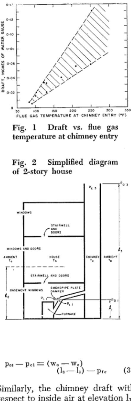
Fig. 1 gives results of the clraft measurements related to flue gas temperatures at chimney e i ~ G . ~ . Values fall within the cross-hatched area; some spread is expected as measurements mere taken under differing conditions of flue gas volume. Outside temperatures dur- ing the measurements were be- tween 25 and 34 F. Basement tem- txratures were near 70 F. Draft at
L
the smokepipe plate damper was not measured but would have been less than at the chimney by the amount required to overcome smokepipe pressure losses. Thus, under the coilditions shown at the lower end of the graph, venting failure was imminent. Some of the factors contributing to these condi- " tions are apparent, but the actual mechanism by which venting fail- ure occui-red can be fully explained only by considering the inter-rela- tion of draft and house pressures.
INTER-RELATION O F DRAFT AND HOUSE PRESSURES Fig. 2 is a simplified diagram of a two-level house with basement and attached chimney. Elevation 1, represents the level of the neutral zone where the absolute pressures inside and outside are equal. Ele- vation 11 represents the location of any opening between the venting system and the house, such as a smokepipe plate damper, a baro- metric damper, or a draft hood. Venting failure occurs when the pressure in the venting system at this location, p,l, is greater than the pressure in the house a t the same level, p l l . Since pressure p,, at the cllimney exit is equal to the outside pressure pO3 at the same elevation, 1,
,
pel = paa
+
wc (1s - 11)+
ptc (1) wherew, = mean weight of flue gas, lb per cu f t
pt, = pressure loss in the chimney due to flow resistance, lb per sq f t
The outside pressure a t elevation 11 is
pol = p ~ a
+
TVO (13-
11) (2) wherew, = mean weight of outside air, lb per cu f t
The chimney draft with respect to outside air at elevation l1 is then
Fig. 1 Draft vs. flue gas temperature at chimney entry Fig. 2 Simplified diagram of 2-story house
pol - pc, = (wo - w e )
1 - 1 - 1 ( 3 )
Similarly, the chimney draft with respect to inside air at elevation 11,
p , ,
-
p,1= wo (1.3 - 12)+
w , (I,-
11) - TVc (1.3 - 11)+
pt1 -Pr. ( 4 ) where
w , = mean weight of inside air, lb per cu f t
p t l = pressure loss in the house clue to resistance to flow be- tween elevations ll and 1. The resistance to flow between levels within the house is usually negligible and the difference be- tween the chimney draft with re- spect to outside and inside air is
p,, - p,1= (wo-w1) (12-11) ( 5 ) Equation (4) shows that vent- ing failure and spillage of flue gas into the house from openings at elevation 11 will occur if
wo (la - 12)
+
w , (19-
11)s
w 1 - 1 1
+
P C-
P I ( 6 )Thus the location of elevation I,,
the neutral zone, has a n effect on draft with respect to inside air and is related to draft failure. If eleva- tion 1, = 11, the draft with respect to inside and outside air will be equal at elevation l1 and will be zero when the mean temperature of the flue gas in the chimney, T,, is equal to the outside temperature, To, ignoring friction effects.
Similarly, if elevation 1, = 13, the draft will be zero when T, is equal to the mean temperature in the house, T i . If there is flue gas flow in the venting system, friction losses must be overcome. These limits of mean flue gas tempera- ture, below which venting f a1 '1 ure occurs, will be correspondingly higher. An increase in the mean flue gas temperature of approxi- mately 10 F would normally be adequate to overcome these fric- tion losses with the small flue gas volunles iilvolved when venting failure is imminent.
Wind pressures may affect the neutral zone location, and, in adcli- tion, will usually have some direct effect on pressures at the chimney exit. Wind effects are beyond the scope of this paper. Under calm or low wind conditions, the level of the neutral zone will usually be at some elevation between l1 and 1,
and will depend on the location and characteristics of the openings between the house and outside.
Data on the locaiion of the neutral zone in houses are limited. Available records indicate that it may often be well above the inicl- height of the heated structure. I t follo\vs that opening basement windows will have a beneficial effect on draft, but openings at upper levels may affect clraft ad- versely. Appliances that exhaust air from the house have the same effect as openings above the neu- tral zone. In a tight house these might lower housc prcssures below outside pressures at all levels, creating an imaginary neutral zone above the heated structure. I t will be recognized that the chimney itself represents one of the upper openings. In a tight house or en- closure the chimney might have an effect on the neutral zone similar to a mechanical exhaust unit.
T h e mechanism of draft fail- ure described previously applies directly to conditions found at the housing developments referred to.
CHIMNEY
L OF PRESSURE
Fig. 3 Location of pressure
taps and chimney thermocouples
It can be assumed that the neutral zone was at an upper level in the house, particularly at night when upstairs windows are open, and at times the mean flue gas tempera- ture fell below the critical value defined by Equation (6). It is clear that to avoid this cause of venting failure the mean flue gas tempera- tures in the chimney cannot fall much below mean house tempera- ture.
Several factors contributed to the lowering of mean flue gas tem- perature below this value. Low rates of combustion, dilution of flue gases at the smokepipe plate damper, and cooling of the flue gases in the long smokepipes re- sulted in relatively low flue gas temperatures upon entrance to the chimney. These temperatures were still higher, however, than the house air, and the effect of cooling the flue gas in exposed outside chimneys must be considered the ultimate cause of draft failure.
The temperatures at the exit of the chimneys where venting .
failure occurred were not meas- ured. Subsequently, however, some temperature records were obtained for three chimneys of similar con- struction venting oil burning fur- naces. Two of these chimneys were on outside walls, one 27 ft and the other 19 ft high. The third was an inside chimney 22 ft high; 12 ft within the heated structure, 7 ft in the attic, and 3 ft above the roof. Following an 8-1u burner-off pc- riod, when outside temperature was 40 F, the flue gas temperatures at chimney exit were 47, 48, and 65 F, respectively. Venting failure of the type described, with solid- fuel hand-fired furnaces, is unlikely
to develop when inside chimneys are used.
Similar venting problems can be expected when heating units burning other fuels operate at low or pilot fire during mild weather, although spillage of the products of combustion into the house might not be regarded so seriously. It follows that inside chimneys would also be advantageous in these instances. On the other hand, mechanical oil-burning furnaces operate at rated input on heat de- mand, regardless of the outside temperature, and the same problem of venting failure due to low flue
Fig. 4 Draft during furnace
start-up, following extended off periods
-
L(a1 OUTSIDE TEMPERATURE 36 O F
u
l b l OUTSIDE 'TEMPERATURE 27 O F
TIME (SECONDS)
(cl OUTSIDE TEMPERATURE 6 'F
gas temperatures does not occur. However, the draft condition dur- ing start-up of such furnaces, and the extent to which this is affected by the draft prior to start-up, are
of special interest. Since the aver- age temperature of gas in the chimney can be relatively low, the effect of house pressures on the chimney draft prior to starting of the burner is next considered.
MEASURING CHIMNEY DRAFT AND HOUSE PRESSURES
Measurements of chimney draft and house pressures were made in a single-story house with basement, heated by a forced warm-air sys- tem with high-pressure gun-type oil burner. The house had a floor area of 1200 sq ft and was well insulated, with plaster finish throughout. Storm windows and doors and weatherstripping were used. There was a covered hatch in the hall ceiling leading to a vented attic.
The chimney was on an out- side wall and exposed to the weather on three sides. It was con- structed of single layer brick with clay-tile flue liners and contained a nominal 8- by 8-in. flue serving the furnace and a nominal 8- by 8-in. flue serving a fireplace. The furnace room was open to the basement which was intercon- nected to the main floor though the return air system. The oil burner was equipped with a 0.75- gph ilozzle and the air supply was adjusted to give No. 2 smoke spot with about 5% CO,. The flue pipe was 6 ft long and contained a barometric damper, which was partly open even when the furnace was off.
Pressure taps were located in the cap of the combustion ch'unber sight-port t o measure overfire draft, in the flue pipe at chimney entry to measure chimney draft, in the four outside walls and ceiling to measure pressure differences across the building enclosure, and at ail outside pressure station in the backyard approximately 80 f t from the rear of the house. Pressure measurements were made with an electric capacity-type differential pressure meter. This provided a current output proportional to pres- sure, which was measured on a galvanometer-type recording milli- ammeter. The pressure meter was
TABLE I
HOUSE PRESSURE VS. BACKYARD, ATTIC AND CHIMNEY AS AFFECTED BY HOUSE OPENINGS, WITH FURNACE OFF
Arrangement
~ f .
Openlngs Openings closed Basement window open A t t i c hatch open Fireplace damper openPressure Differences, In. of Water
Backaid (31 (4)
11
Chimney ( I ]T l = 7 2 F T 1 = 7 0 F T 1 = 7 2 F T i = 7 0 F T i = 7 2 F
T 0 = 2 7 F T o = 6 F T 0 = 2 7 F T o = 6 F T 0 = 2 7 F
TABLE II
HOUSE PRESSURE VS. CHIMNEY AND OUTSIDE WITH FURNACE OFF AND ON
I Pressure Differences, in. of water
TI = 70 F
chimney' Overfire' Backyard A t t i c North East South W M ~
To= 6 F
1
( I1
(211
(311
(41 (51 (611
0 1 (81---
Furnace off 0.020 I 0.019
1
-0.018 0.01 1 4 . 0 0 7 4 . 0 1 0 4 . 0 0 8 0.000Furnace on
1
0.065/
0.035/
-0.0231
0.007 1 4 . 0 1 2I
4 . m 3 1 4 . 0 l 21
-0.004sensitive to pressure charges of less than 0.001 in. of water and was calibrated against a laboratory micromanometer having a corre- sponding accuracy. The zero-posi- tion of the meter, however, drifted with temperature and line voltage fluctuations and frequent checking was necessary.
Flue gas temperatures in the chimney, along the center of the flue, and outside temperature were measured with copper-constantan thermocouples connected to a 16- point electronic temperature re- corder. Location of the chimney thermocouples with respect to the center of the chimney thimble and location of pressure taps with re- spect to the level of the pressure meter are shown in Fig. 3. Inside air temperature was measured with a calibrated thermograph at one location only, in the living room approximately 2% ft from the floor. This has been taken as the mean house temperature in subsequent calculations.
Table I shows, for two differ- ent outside temperature conditions, the effects of openings to the out- side at different levels on house pressure (at the meter) relative to backyard, attic and chimney pres- sures. These records were obtained on relatively calm days, during
periods when the furnace was off. When there is no wind, the pressure reading obtained with the meter connected to tap 3 is equiva- lent to the pressure difference across the building enclosure at the level where the connection from inside to outside is made. If there is wind, the reading merely repre- sents basement pressure with ref- erence to the backyard tap. The reading obtained with the meter connected to tap 4 is equivalent to the pressure difference across the ceiling. The house chimney effect required to produce these pressure
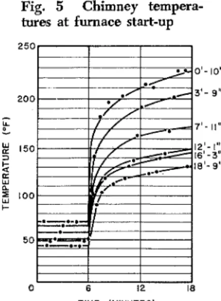
Fig. 5 Chimney tempera-
tures at furnace start-up
TIME (MINUTES)
differences can readily be calcu- lated from the difference in den- sity between inside and outside air, and a neutral level established with reference to the pressure taps; although where the pressure differ- ences are extremely low, small errors in pressure or air density can lead to significant errors in the calculation.
From the results for an out- side air temperature of 27 F, the neutral level, calculated with ref- erence to the attic pressure, is ap- proximately 4 f t below the ceiling with the basement window shut, and approximately 12 f t below the ceiling with it open. This shift of the neutral level below the base- ment window can be explained by outside wind pressure. There is a corresponding increase in chimney draft with the basement window open. I t is anomalous that the basement pressure measured with respect to the backyard tap did not increase to the same extent when the basement window was opened. Opening the attic hatch raised the neutral zone to the ceiling level and had a corresponding effect in lowering chimney draft. A similar study of the results for an outside air temperature of 6 F indicates that opening the basement win- dow lowered the neutral level ap- proximately
7%
ft, while opening the fireplace damper raised it ap- proximately 2% ft.Table 11 gives some additional pressure measurements, taken under the same conditions as those in Table I for an outside tempera- ture of 6
I?.
Calculated neutral levels vary from 3Yz f t below the ceiling with reference t o the west wall to 1 f t below the ceiling with respect to the east wall, indicating some easterly wind effect. Simi- larly, the neutral level is 5% ft below the ceiling with reference to the attic tap and at the ceiling with respect to the backyard tap. With the furnace on and other conditions the same, the neutral level is approx 2 ft higher with ref- erence to all taps, a result of the increased flow up the chimney.It should be pointed out in connection with calculated neutral pressure levels, that the house had a total door and window crackage of about 260 lineal ft. Basement windows, not well weatherstripped, represented 35 ft. Living room
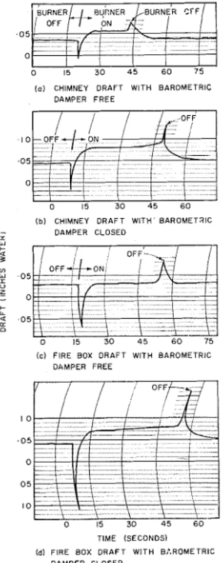
(o) CHIMNEY DRAFT W l T H BAROMETRIC DAMPER F R E E 0 15 3 0 45 6 0 (b) CHIMNEY D R A F T W l T H BAROMETRIC - DAMPER CLOSED I
(c) FIRE BOX D R A F T WlTH BAROMETRIC DAMPER FREE \ \ 0 15 3 0 4 5 6 0 TIME (SECONDS) (dl F l R E BOX D R A F T W l T H B:.ROMETRIC DAMPER CLOSED
Fig. 6 Draft during burner start-up following normal fur-
nace operation with outside temperature at 5 F
windows were fixed and ventilation was provided by louvred openings with weatherstripped covers just above floor level, contributing 40 ft. Thus, there may have been more cracks immediately above and below the floor than is usual, and neutral levels may have been correspondingly lower.
Table 111 presents some fur- ther records of the effect of house openings on chimney draft under mild weather conditions. With the furnace off, opening of the base-
TABLE Ill
EFFECT OF HOUSE OPENINGS ON CHIMNEY DRAFT
T, = 72 F
/
Chimney draft, in. of waterTo = 36 F j Furnace off i Furnace on-
-
:
. I 0 . 0 5 1 " 5 . o-
I- 2 . 0 5 a 0 15 3 0 4 5 6 0 D T I M E ( M I N U T E S ) Openings closed/
0.010 Basement window; 0.0 16 openFig. 7 Chimney draft after burner shut-down with out- side temperature 27 F
0.066 0.075
ment window raised the draft about 0.006 in. of water, while opening the attic hatch lowered it by about 0.005 in. of water. With the furnace on, the effect of open- ing t h e window is somewhat greater, while opening the attic hatch has a lesser effect.
Fireplace
1
0.005 0.063 damper open1
DRAFT DURING BURNER START-UP
Several tests were made with this same installation, in which the chimney or overfire draft was re- corded during burner start-up. Fig. 4 gives the results following ex- tended furnace-off periods at dif- ferent outside temperatures. The accuracy of these measurements of transient draft has not been estab- lished. The galvanometer pen was delicately balanced to minimize drag, and the galvanometer was critically damped to eliminate over- shooting. Any errors are thought to be mainly in the measurement of extremes in pressure when pres- sures were rapidly reversed.
Fig. 4(a) indicates that sub- stantial positive pressures can oc- cur for a brief period in the fire box when the burner-blower first starts. Maximum pressure meas- ured in this test was just uncler 0.15 in. of water. Draft failure in the fire box, occurred for about 5 sec. I11 this instance, the f ~ x n a c e had been off overnight and the temperature in the center of the flue varied from 69 F at the bottom to 49 F at the top prior to burner start-up. The chimney draft was 0.010 in. of water, as shown in Table 111. Fire box draft after burner start-up surpassed that prior
to start-up in about 61/2 sec. Figs. 4(b) and 4(c) show the extent of positive pressure at the base of the chimney during burner start-up following extended pe- riods with tlle furnace off. Tem- peratures from bottom to top of the chimney were 77 to 61 F and
70 to 43 F, respectively. Draft failure a t the base of the chimney existed for about one sec in both instances. Chimney draft with the burner operating exceeded that with the burner off after 2% sec. Draft build-up was relatively rapid in all cases.
There was a corresponding rate of increase in chimney flue gas temperature, as shown in Fig. 5 for the conditions of Fig. 4(c). The curves from top t o bottom represent the temperatures at the tl~ermocouple positions shown in Fig. 2, in order, from the bottom to top of the chimney. T h e print and chart speed of the tempera- ture recorder were not sficiently fast to show the precise pattern of temperature change during the first few seconds of furnace operation. As mentioned earlier, the bar- ometric damper was partly open even when the furnace was off. This no doubt led to higher chim- ney temperatures than would have occurred otheiwise, during ex- tended periods with the furnace off. The position of the barometric damper also affected the maximum pressures a t the base of t h e chim- ney and in the fire box during buiner start-up. This can be seen in Fig. 6, ~vhich gives the results of chimney and fire box draft measurements with the barometric damper in its normal free position and taped closed. All results in this figure were obtained within a short period under essentially the same conditions.
In each case the furnace was allowed to run for less than one mill and the system allowed to cool until the chimney draft returned to its original value, with the baro- metric damper free, before begin- ning another on-cycle. T h e outside temperature was 5 F and the burner had been cycling normally before the measurements were taken, ac- counting for the relatively high chimney draft prior to each burner start.
Higher positive pressure oc- curred both in the fire box and at the base of the chimney when the barometric damper was closecl, in- dicating that these pressures are re- lieved, to some extent, by gas flow out of the barometric damper. The rate of draft recovery was some- what greater with the barometric damper closed, probably due to
the higher flue gas temperatures in the chimney, as well as the greater difference between nlaximum pres- sure in the chimney or fire box and ~ o t e n t i a l for draft. The nosition of
L I
the barometric damner in this in- I stance had little effect on the pe- riod of draft failure, being less than 1 sec at the base of the chim- ney and 2 or 3 sec in the fire box. In comparing the results in Fig. 4 with those in Fig. 6, it must be noted that the burner nozzle size was 0.75 gph for the former, but was changed to 0.65 gph for the latter, with a corresponding throttling of the air supply to the burner blower. Thus, both the higher draft before start-up and the reduced capacity of the burner blower probably account for thc lower positive pressures and shorter periods of draft failure shown in Fig. 6.
Sudden increase in draft at the moment the oil burner stops, in Fig. 6, is of academic interest. The rate at which the draft sub- sequently decreases is more im- portant, since it relates to the draft available at the beginning of the next on-period. Fig. 7 is a record of chimney draft following extended burner operation, the beginning of which is shown in Fig. 4(b). The draft decreased rap- idly for tlle first few minutes but was still nearly 0.03 in. of water after 50 min. Previously, the draft had decreased to 0.016 in. at the end of a 4-hr off-period. In a com- parable test with an outside tem- perature of 6 F, similar results were obtained. The draft fcll from 0.065 in. to 0.04 in. in about 15 min but was still above 0.03 in. one hr after the burner stopped. Fig. 4(c) shows that the draft was 0.02 in. of water after a 6-hr burner-off period at this outside temperature. The rate of draft decrease will de- pend on several variables; these re-
sults are, therefore, specific to the installation tested.
CONCLUSION
An analysis has been made of draft failure with residential heating units operating at low rates of combustion during mild, calm weather. It has been shown that under these conditions the relation between chimney draft and house pressures becomes important in de- termining when venting failure will occur. A simple equation ex- pressing this relation has been developed. It shows that draft failure will occur if the mean flue gas temperature in the chimney falls below a value that depends on the neutral zone level.
Under the most ullfavorable conditions, excluding the effect of wind, draft failure occurs when the mean flue gas temperature in the chimney is less tllm the mean house temperature. Measurements have shown that this can occur with masonry chimneys located at an exterior wall and exposed to the weather on three sides, but it is unlikely when cl~imneys of similar construction have a substantial proportion of their length located within the heated structure.
Measurements of chimney draft and house pressures in a sin- gle-story house with an oil-fired fuinace have demonstrated that draft, either with the burner on or off, is increased by lowering the neutral zone and decreased by rais- ing it by an amount which corre- sponds to the change in house pres- sure at the furnace. The effect of furnace operation on the level of the neutral zone has also been shown. Measurements on a furnace with a high pressure oil burner have established that substantial increases in pressure occur in the fire box during start-up and that positive pressures may exist for several seconds.
Similar increases in pressure,
of lesser magnitude, occur at the base of the chimney. The amount of positive pressure and the period over which draft failure occurs de- pends, to some extent, on the draft available prior to start-up. It ap- pears, also, to depend on the adjustment of the burner blower. Adjustment of the barometric damper affects the positive pres- sures developed, since it acts as a relief opening. Draft recovery after burner start-up was quite rapid in the installation tested, even follow- ing long bunler-off periods. De- velopment of draft, following ini- tial draft loss on start-up, was per- haps aided by the burner blower. It would be interesting to measure the development of draft on start-up with units relying en- tirely on natural draft for combus- tion air supply, especially under conditions where no prior draft was available.
The developme~lt of furnace units with instantaneous b i n g rates modulated in accordance with heat requirements, in contrast with on-of3 firing, has often been ad- vocated to improve heating sys- tem perfolmance. It may be noted that draft failure, similar to that described in this paper, is a po- tential problem with such units, while it is largely avoided with on-off firing as commonly em- ployed.
ACKNO\VLEDGIMENTS
The author wishes to thank C. Wachmann for his pa~ticipation in the analysis of draft failure and R. G. Evans, laboratoly technician, for his assistance with the field measurements. The advice of Dr. N. B. Hutcheon, Assistant Director of the Division of Building Re- search, is gratefully acknowledged. This is a contribution from the Division of Building Research, Na- tional Research Council, Canada, and is published with the approval of the Director of the Division.
Reprinted from the December 1960 issue of tlie ASHRAE JOURNAL, official publication of the Aniericnn Society of Heating, Refrigerating :md Air-Conditioning Engineers. ASHRAE does not necessarily agree witli statements or opinions advanced in its nieeti~igs or printed in its publications.