HAL Id: hal-01406078
https://hal.archives-ouvertes.fr/hal-01406078
Submitted on 22 May 2018
HAL is a multi-disciplinary open access
archive for the deposit and dissemination of
sci-entific research documents, whether they are
pub-lished or not. The documents may come from
teaching and research institutions in France or
abroad, or from public or private research centers.
L’archive ouverte pluridisciplinaire HAL, est
destinée au dépôt et à la diffusion de documents
scientifiques de niveau recherche, publiés ou non,
émanant des établissements d’enseignement et de
recherche français ou étrangers, des laboratoires
publics ou privés.
Front propagation in a vortex lattice: dependence on
boundary conditions and vortex depth.
Edouard Beauvier, Simona Bodea, Alain Pocheau
To cite this version:
Edouard Beauvier, Simona Bodea, Alain Pocheau. Front propagation in a vortex lattice: dependence
on boundary conditions and vortex depth.. Soft Matter, Royal Society of Chemistry, 2016, 12,
pp.8935-8941. �10.1039/c6sm01547f�. �hal-01406078�
Front propagation in a vortex lattice : dependence on boundary
con-ditions and vortex depth
†
E. Beauvier,
aS. Bodea,
aand A. Pocheau
aReceived Xth XXXXXXXXXX 20XX, Accepted Xth XXXXXXXXX 20XX First published on the web Xth XXXXXXXXXX 200X
DOI: 10.1039/b000000x
We experimentally address the propagation of reaction-diffusion fronts in vortex lattices by combining, in a Hele-Shaw cell and at low Reynolds number, forced electroconvective flows and an autocatalytic reaction in solution. We consider both vortex chains and vortex arrays, the formers referring to mixed free/rigid boundary conditions for vortices and the latters to free boundary conditions. Varying the depth of the fluid layer, we observe no variation of the mean front velocities for vortex arrays and a noticeable variation for vortex chains. This questions the two-dimensional character of front propagation in low Reynolds number vortex lattices, as well as the mechanisms of this dependence.
1
Introduction
Stirred flows are well-known to enhance the transport proper-ties of a medium by their ability in intimately mixing compo-nents. This feature extends to reacting flows, as the net reac-tion time of a medium is found to sharply decrease with the stirring rate. In particular, in regimes where reaction proceeds by the propagation of fronts separating reacted and unreacted zones, the mean front velocity is found to largely increase with the vortex intensity. Important consequences follow in the fields of combustion1, chemistry2,3 or even ecology4–6. However, the actual mechanisms of front velocity enhance-ment as well as the whole factors on which this velocity de-pends call for a better understanding in both turbulent1,7–12 and laminar13–21contexts.
We focus attention here on laminar single scale flows made of a periodic planar array of vortices. Propagation of fronts in this context has been addressed by theories13–16and
numer-ical simulations14–17by considering a two-dimensional array
of vortices involving equal width and length. The same bound-ary conditions (hereafter called b.c.) were thus displayed on all their separatrices (actually the free b.c. provided by neigh-bor vortices) and the set of separatrices was found to form a square array. In comparison, apart from a study in Tay-lor vortex flows21, experiments18–20addressed a single chain of vortices confined in a channel. Then, different boundary conditions were applied on vortex separatrices depending on whether they were a channel wall (rigid b.c.) or a frontier with
† Electronic Supplementary Information (ESI) available: Movies of front propagation in a channel accelerated 25 times. Movie ”FreeBC” : large channel (5 vortices between walls) and free effective boundary conditions, U/V0= 35. Movie ”RigidBC” : narrow channel (1 vortex between walls) and
rigid effective boundary conditions, U /V0= 27. See DOI: 10.1039/b000000x/ aAix Marseille Univ, CNRS, Centrale Marseille, IRPHE, Marseille, France
a neighbor vortex (free b.c.). In addition, all experiments nat-urally took place in a fluid layer whose depth d was thus a natural parameter of them.
Usually, experiments involved a single vortex depth d. However, one of them varied this parameter and concluded that the mean front velocity Vf not only depends on the vortex
intensity but also on the vortex depth d19,20. As it was
per-formed in a vortex chain, it involved mixed free/rigid bound-ary conditions on vortices. Its vortices were also longer than large, so that the set of separatrices was rectangular instead of square19,20. Accordingly, this experiment involved two kinds of asymmetry : (i) a boundary asymmetry yielding different b.c. on a vortex, (ii) a geometric asymmetry induced by the difference between vortex width and vortex length.
As theories or simulations considered a two-dimensional planar flow, they implicitly assumed a 2-dimensional character of front propagation in a vortex lattice13–17. However, the de-pendence of Vf on d questions this assumption and raises the
following interrogations regarding its possible origin : could it follow from the geometric asymmetry of vortices or from their boundary asymmetry and then, by what kind of mechanism ? In particular, could it refer to a modification of the structure of a still planar flow or to the occurrence of secondary flows breaking the planar flow assumption ?
To answer these questions, we perform here front propaga-tion experiments in an array of vortices involving equal width and length and either similar or different boundary conditions on their separatrices. We then vary the channel depth so as to highlight the implications of geometrical symmetry and of boundary symmetry on the dependence of front propagation on channel depth. Altogether, this provides the first compari-son of the effects of boundary conditions and of vortex depths on front propagation in a stirred medium.
The experimental set-up allowing these configurations to be achieved is reported in section 2. We then address qualitative and quantitative results on section 3 and discuss them in sec-tion 4. A conclusion about the study and its general issue is drawn in section 5.
2
Experiment
The experiment is conducted in a fluid enclosed in a channel with top, bottom and lateral boundaries and whose depth d is imposed by spacers (Fig.1-a). Three depths have been consid-ered : d = 2, 4 or 6 mm.
Flows are induced by electroconvection thanks to both a pattern of magnets placed below the channel and an electric current imposed by electrodes placed at the extremities of the fluid layer (Fig.1-a). All the magnets are squares with dimen-sion L = 20mm. They are placed one beside the others so as to form a square lattice. Their magnetization direction alternates between neighbors. It thus induces in the fluid layer a peri-odic magnetic field and thus periperi-odic Laplace forces which give rise to alternating vortices. Electromagnetic forcing has been used for a while in many different contexts ranging from boundary layer effects in salty water22,23, mixing24,25, single scale flows26–28multi-scale flows29or quasi-two dimensional turbulent or chaotic flows30–32. Beyond hydrodynamics, it has also been used to study front propagation18–20 in a laminar regime. In particular, in the Stokes regime in which our exper-iment fits, the current density, the magnitude of the Laplace force density and then the vortex intensity are all proportional, thereby providing a simple mean to tune the flow magnitude by the current intensity.
Front propagation is provided by an autocatalytic oxydo-reduction reaction between chlorite and iodure ions in the fluid layer :
ClO−2+ 4I−+ 4H+ → Cl−+ 2I2+ 2H2O (1)
5ClO−2+ 2I2+ 2H2O → 5Cl−+ 4IO−3+ 4H + (2)
IO−3+ 5I−+ 6H+ → 3I2+ 3H2O (3)
The autocatalytic feature is provided by the fact that the con-sumption of iodide I−worked out in (1) is enhanced in (3) by a product of reaction, the iodate IO−3 produced in (2) thanks to the iodine I2provided by the consumption of iodide itself in
(1) and (3). This provides a positive feed-back of iodide con-sumption on itself possibly yielding a run-away and, in spe-cific regimes, a reaction zone localized in a thin interface, the front, standing in between reacted and unreacted zones33,34. The detection of these zones, and thus of the front as their frontier, is provided by a change of colour as reaction pro-ceeds. For this, a Starch indicator introduced in the solution forms a blue complex with iodide and iodine which disappears after reaction following the depletion of iodide. The unreacted
blue zone then transforms into an uncolored reacted zone. The front velocity may thus be deduced from the kinematics of their frontier, as recorded on a computer by a camera (Fig.2). In a fluid at rest, this velocity is labelled V0and amounts in our
experiment from 1.0 to 1.4mm/mn depending on the imposed current density19,20. For this, the temperature has been stabi-lized to 20◦Cto minimize the variability of V0to less than few
percents.
When the medium is stirred by the vortex lattice, front prop-agation may take advantage of advection. This is in particular so when the front is enrolled by vortices. Then, following the large value of the flow velocity compared to the proper front velocity V0(from 5 to 40 times greater here), the front
veloc-ity stays close to it. In particular, it appears that at large flow velocity, after having crossed a vortex separatrix, the front is advected on a streamline (Fig.2) where its mean velocity pro-vides a direct information on the vortex intensity U . Thanks to the linear relationship between flow velocity and current den-sity, this determination may then be extended on the whole range of the experiment.
Considering a planar vortex flow V, its advective term V.∇V may be estimated to about U2/L in the bulk since the variation scale in the flow plane is then L. However, close to a lateral boundary, this scale decreases to about the chan-nel depth d, yielding another estimate of about U2/d there. In both cases, the dissipative term ν4V may be estimated to νU /d2for a near Poiseuille profile where ν ≈ 1 mm2/s de-notes the water viscosity. Accordingly, the Reynolds num-ber reads Re = U2d2/νUd ≡ Ud/ν close to a boundary and
Re0= Re d/L < Re in the bulk. As L = 20mm, one gets in our experimental range U ≤ 40mm/mn, 2 ≤ d ≤ 6, a maximal Reynolds number Re0= 1.2 in the bulk and Re = 4 close to boundaries. Accordingly, the experiment may be considered to stand within or close to the Stokes regime.
The channel is 400 mm long and either 20, 80 or 100 mm large. In particular, its width could then include 1, 4 or 5 mag-nets. Placing the channel sides on magnet boundaries, this provided 1, 4 or 5 vortices in between them (Fig.1-b,c). As these vortices display equal length and width, they satisfy the geometrical symmetry. When a single vortex fits in between the channel width, it undergoes rigid b.c. on the separatri-ces made by the channel sides and free b.c. on the remaining ones made by the frontier with neighbor vortices. This mixed case corresponds to asymmetric boundaries (Fig.1-b). In con-trast, when the channel width is large compared to the vortex size, the experiment shows that front propagation in the cen-tral vortices is favored, so that they act as a leading zone for the overall propagation (Fig.2-a). As these central vortices are surrounded by other vortices, their b.c. are free on all their sep-aratrices. This corresponds to symmetric boundaries (Fig.1-c). This way, the set-up is able to provide an experimental achievement of front propagation with geometric symmetry
Fig. 1 Sketch of the set-up showing the chemical solution stirred by Laplace forces induced by an electric current flowing over alternate magnets (a) and the resulting chain (b) or array (c) of counter-rotating vortices. The magnetic field and the electric current are labelled B and I and the channel depth and the vortex size d and L respectively. Vortex boundary conditions are mixed free/rigid (b) or free (c), depending on whether vortices make contact with the channel sides (b) or are surrounded by other vortices (c ; except for side vortices).
and either symmetric or asymmetric boundaries.
3
Fronts and Velocity
We report typical evolutions of fronts in the vortex lattice to-gether with quantitative measurements of their mean front ve-locity Vf along the channel axis, at various vortex intensity U
and channel depths d. The two situations of free b.c. (symmet-ric vortices) and mixed free/rigid b.c. (asymmet(symmet-ric vortices), are considered to allow for their comparison.
3.1 Symmetric vortices : free b.c.
Here, the channel width englobes 4 or 5 vortices, so that 2 or 3 central vortices undergo free b.c. on all their separatrices (Fig.1-c). A typical evolution of reaction fronts is reported on figure 2-a. It appears that the fronts display a periodic motion involving alternating phases between a slow crossing of sep-aratrices and a quick advection in between. In addition, the contamination of a new line of vortices always occur on cen-tral vortices so that the mean front propagation is actually set by symmetric vortices.
Figure 3-a reports, at various channel depths, the enhance-ment of the mean front velocity Vf by the flow in term of
non-dimensional variables Vf/V0, U /V0. It appears no definite
de-pendence on the channel depth d, the velocity enhancement displaying the same linear trend in this velocity range. This denies relevance of the channel depth d on the mean front propagation, in agreement with a two-dimensional view of this propagation issue.
3.2 Asymmetric vortices : mixed free/rigid b.c.
Here, the channel width englobes only a single vortex which thus undergoes mixed free/rigid b.c (Fig.1-b). Regarding front
motion, the typical evolution of reaction fronts reported on fig-ure 2-b shows that the quick advection phase occurs near the channel sides. As in the previous symmetric situation, fronts undergo a periodic motion made of a succession of slow cross-ing of separatrices and quick advection in between, but the latter occurs close to a rigid b.c. this time.
Figure 3-b reports, at various channel depths, the enhance-ment of the mean front velocity Vf by the flow in term of
non-dimensional variables Vf/V0, U /V0. It shows evidence
of a dependence on the channel depth d, the velocity en-hancement displaying an increasing concavity with the chan-nel depth. This reduction of velocity enhancement at large d yields in particular, at U /V0≈ 26, a decrease of about 40% of
the mean front velocity Vf when increasing the channel depth
from d = 2mm (Vf/V0= 11.7) to d = 6mm (Vf/V0= 6.8).
This evidences a noticeable influence of the channel depth on front propagation, a fact which questions the two-dimensional assumption considered in theories and simulations13–17.
4
Discussion
Experimental data on velocity enhancement by vortices reveal an ambivalent behavior regarding the dependence on the chan-nel depth : no dependence for free b.c. ; a noticeable de-pendence for mixed free/rigid b.c.. As these data have been obtained on vortices involving equal length and width, this in-dicates that their dependence on d has to be traced back not to geometrical asymmetry19,20but to the asymmetry between the boundary conditions applied at the vortex periphery.
For all vortices, rigid b.c. are in order at the top and bot-tom plates. However, for mixed free/rigid b.c., rigid b.c. are also undergone at two opposite separatrices of vortices. We discuss the implications of these features on front propagation and especially its evolution with the channel depth.
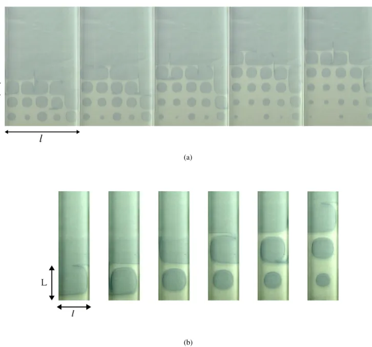
(a)
(b)
Fig. 2 Front propagation in a vortex array (a) or in a vortex chain (b). Times regularly increases from left to right while fronts propagate upwards. The vortex size is L = 20mm, the channel depth is d = 2mm and the channel width is labelled l. (a) Free boundary conditions, except for the side vortices. l/L = 5, U /V0= 17.3. Time interval between pictures : 65s. (b) Rigid lateral boundary conditions. l/L = 1,
U/V0= 14.6. Time interval between pictures : 58s.
4.1 Symmetric vortices : free b.c.
The rigid b.c. on the top and bottom plates of the channel imply a near parabolic profile of the flow field on the channel depth direction z. Nevertheless, front propagation shows no dependence on its extent d. This feature is coherent with :
1. planar flows involving a common structure U indepen-dent of z and d and an intensity simply varying with z on the depth axis : V = f (z/d)U, the flow U belonging to
the plane (x, y) and being only dependent on its variables : U ≡ U(x, y).
2. a front propagation monitored by the planar flow U, in-dependently of the z-profile f (z/d).
The first feature is reminiscent of a Poiseuille flow and may be thought to be satisfied for electroconvective flows at the dominant order. The second feature follows from the local relationship between front velocity and flow, as studied on a
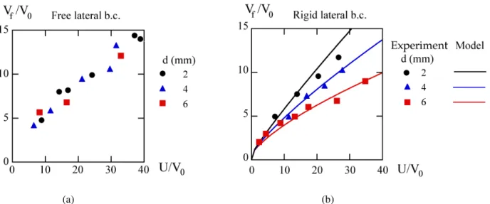
(a) (b)
Fig. 3 Reduced front velocity Vf/V0as a function of the reduced vortex intensity U /V0. (a) Free b.c. : a single linear relationship is displayed
whatever the channel depth d. (b) Mixed free/rigid b.c. : concave relationships are displayed with a concavity increasing with the channel depth d. Lines correspond to predictions from an optimization model19,20.
Poiseuille flow35,36. It was then found that front velocity turns out to be the sum of the proper front velocity V0 plus either
the mean flow velocity on the channel depth for low enough d compared to the front thickness (i.e. η = dV0/2D < 1)
or the maximal flow velocity in the opposite case35,36, D = 2.10−3mm2/s denoting the molecular diffusivity of the rele-vant species. In all cases, front velocity appears as the sum of V0and a velocity linearly related to U by a constant prefactor.
In particular, in our experiment, as η is larger than 8, fronts locally advance at velocity V0+ U(x, y).n where n denotes the
front normal in the mid-depth plane z = d/2 and where the z-profile has been normalized so that f (1/2) = 1.
Altogether, both features may thus be thought as relevant for explaining the independence of mean front velocity on d.
4.2 Asymmetric vortices : mixed free and rigid b.c.
In comparison to the above case of symmetric vortices, the dependence of mean front velocity on d displayed when some vortex boundaries are rigid calls for either a structure of pla-nar flows dependent on d or a breaking of the plapla-nar flows assumption.
4.2.1 Dependence of planar flows on d.
This issue has been explored in a previous study where the mean front velocity was argued to correspond to the quick-est trajectory of the front head in the vortex field19,20. Then, an optimization model based on a simplified family of trajec-tories inspired by observations was worked out to derive the
mean front velocity within a prescribed modeling of planar flows. In particular, these flows involved circular streamlines and boundary layer thicknesses of half the channel depth. The latter feature was motivated by the fact that, in a Hele-Shaw cell, the channel depth monitors the width of boundary layers, following the dominant dissipation implied by the presence of parallel plates. Its value was then taken to be d/2, yielding the quickest streamline to be located at this distance to the chan-nel wall. This constraint thus led the flow field to depend on d. Its implication on the mean front velocity was deduced by se-lecting the trajectory that minimizes the crossing time through a vortex.
The predictions of the optimization model for geometri-cally symmetric vortices are reported on figure 3-b for the three channel depths. They are found to satisfactorily recover the experimental data, especially the increasing concavity of the enhancement curves with the channel depth. Beyond this agreement, it should be realized that the optimization model is based on a phenomenological family of front trajectories and on a crude flow modeling. In particular, the circular form of streamlines stands for an approximation of actual ellipti-cal streamlines, which prevents the flow velocity to vary on them. In this sense, the streamline velocity is intended to re-flect the average velocity on it instead of its local values. It thus corresponds to the nature of the velocity measured exper-imentally and is sufficient to evaluate the advection time of the front head on a streamline. However, this approximation also implies circular streamlines which are obviously inade-quate around the square vortex separatrices, especially around the vortex corners. Finally, the scaling of the boundary layer thickness with the channel depth, although physically sound,
involves an approximate prefactor.
For these reasons, the optimization model must be taken as a toy model whose merit is to provide a kinematic origin for the dependence of front velocity on the channel depth : as the quickest front trajectory proves to belong to the bound-ary layer19,20, front propagation appears to be sensitive to its structure and thus to the channel depth which modifies its thickness. However, beyond this qualitative relevance, the op-timization model appears too crude for allowing a quantitative comparison. In particular, as its major outcome is the sensitiv-ity of front propagation to the structure of the boundary layer, it actually calls for an accurate flow modeling to provide a rel-evant quantitative comparison. In addition, as it relies on a restricted family of trajectories, its predicted mean flow veloc-ities would nevertheless be approximate. Accordingly, given an accurate model of planar flow, a relevant quantitative com-parison to experiment would call either for an extension of the optimization model to any possible trajectory or for numerical simulations.
4.2.2 Breaking of the planar flows assumption. For rotating flows, a generic mechanism for the genera-tion of secondary flows is provided by the Ekman pump-ing37. It relies on the fact that viscous effects at boundaries make velocity and centrifugal force shrink whereas pressure is maintained. This therefore induces a force disequilibrium in the fluid which results in setting the fluid into motion. An-other possible origin for secondary flows is the occurrence of hydrodynamical instabilities but these are not expected at the low Reynolds numbers at which the experiment stands (Re = U d/ν < 4 here ; see section 2). An important difference between these two mechanisms should be noticed : whereas the Ekman pumping must be present at all Reynolds numbers or at none, instabilities manifest themselves above some on-set. Accordingly, if secondary flows are generated by Ekman pumping, their amplitude should continuously grow with the vortex intensity without onset.
In our configuration, this phenomenon underlying the Ek-man pumping might first occur at the top and bottom rigid plates of the channel. It should thus induce inward flows to-wards the vortex centers giving rise, by incompressibility, to flows directed normally to the plates and finally to two spi-ral flows, following the top-bottom symmetry of the config-uration. These secondary flows should however be equally present on symmetric and asymmetric vortices, i.e. for free or mixed free/rigid b.c., since both configurations involve top and bottom plates. No spirals have however been detected from front motion in our experimental range so that the corre-sponding secondary flows are presumably too faint to notice-ably modify front dynamics. Anyway, they could not solely explain the specificity of the asymmetric vortex configuration,
i.e. its noticeable dependence on the channel depth.
In contrast, the presence of rigid lateral b.c. stands as a specificity of asymmetric vortices from which specific inward flows could be generated. They might in particular modify the advection of the front head all along its travel inside the lateral boundary layer and possibly slightly deflect its trajec-tory towards the vortex center. This could result, at the end of the advection phase, in a slight increase of the front distance to the neighbor vortex separatrix. As the front must cross it by its sole propagation at its slow proper velocity V0, this
ef-fect, although faint, could result in a noticeable decrease of the mean front velocity. This mechanism is however in com-petition with the one induced by the increase of the boundary layer thickness of planar flows, since both yield an increase with d of the distance of the front head to the neighbor vor-tex separatrix. Determining the role of each thus calls for a quantitative evaluation of their respective effects.
Beyond the qualitative explanation of secondary flow gen-eration, it should be noticed that a quantitative determination of their amplitude requires first an accurate modeling of the primary flows, i.e. of planar flows. Accordingly, the discrim-ination between the two above mechanisms calls for an accu-rate modeling of planar electroconvective flows in both sym-metric (free b.c.) and asymsym-metric vortices (mixed free/rigid b.c.). Then, the most direct way to determine the implications of these flows on front propagation will be to perform numer-ical simulations. Comparison with experiments could then be able to conclude whether the planar flows for free b.c. as well as their modification by lateral walls allow to recover both the independence to the channel depth d for symmetric vortices as well as the dependence on it for asymmetric vortices.
5
Conclusion
In theories and simulations, front propagation in laminar flows is addressed on two-dimensional flows involving a prescribed structure13–17. This assumption actually denies a relevant in-fluence of three-dimensional features of vortices as their depth or asymmetries induced by boundary conditions or by direct forcing. However, a previous experiment performed on a vor-tex chain enclosed in a channel revealed a variation of the mean front velocity with the channel depth19,20. This
obser-vation thus calls for determining to what extent front propaga-tion in vortex arrays may be considered as 2-dimensional and to what kind of features it may be dependent.
To address this issue, we performed experiments so as to draw the first comparison of front propagation for different flow b.c. : the free b.c. considered in theories or simulations and the mixed free/rigid b.c. involved in the experiment which evidenced a dependence on the channel depth. For this, we considered both narrow and large channels as compared to the
vortex width. Large channels provided effective free b.c., as they leave place for several vortices between their walls (vor-tex array). Narrow channels provided mixed free/rigid b.c. for vortices, as they englobe a single line of vortices between their walls (vortex chain). In both cases and in contrast with a previous experiment19,20, we considered only geometrically symmetric vortices involving equal width and length, as con-sidered in theories and simulations.
The dependence of mean front velocity on channel depth d has been found to be bivalent : no dependence for vor-tex arrays (free b.c.) but a noticeable dependence for vorvor-tex chains (mixed free/rigid b.c.). In particular, in the latter case, the mean front velocity was found to increase as d was re-duced, up to eventually reach at low d the values found on vortex arrays. Thus, in contrast with primary intuition, the most dissipative configuration regarding hydrodynamics (vor-tex chain at low cell depth) provided a similar efficiency re-garding propagative transport as the less dissipative one (vor-tex array). This might provide a mean for restoring in confined systems a propagation efficiency similar to that displayed in unconfined ones. In particular, this property might apply to chemical engineering in stirred systems, possibly even down to microfluidic scales38. It would then stress that the net re-action efficiency in narrow geometries could be monitored by their depth, up to eventually recover in thin configurations the efficiency involved in extended ones.
On the other hand, on vortex arrays, the independence of front velocity from the channel depth shows that the vertical profile of flows plays no significant role regarding propaga-tion efficiency. This property might apply to natural situapropaga-tions which proceed by reaction-diffusion-advection within a set of quasi two-dimensional vortices, such as in plankton dynam-ics4,5 or in ozone hole evolution6. It would then point out the planar structure of their vortices as the essential feature regarding the global dynamics.
Finally, the analysis of the possible origin of the depen-dence of front propagation on channel depth in vortex chains (mixed free/rigid b.c.) has stressed two possible mechanisms : a modification of planar flows by boundary conditions or a breaking of the planar flow assumption by secondary flows. In the first case, front propagation would still be considered as a two-dimensional issue, sensitive enough for being influenced by b.c. ; in the latter case, it could no longer be considered as two-dimensional since noticeably dependent on faint three-dimensional features. Discrimination between these mecha-nisms calls for an accurate modeling of electroconvective pla-nar flows together with simulations of front propagation, so as to provide relevant comparisons to experiments.
Acknowledgments
This work has been carried out in the framework of the Labex MEC (ANR-10-LABX-0092) and of the A*MIDEX project (ANR-11-IDEX-0001-02), funded by the Investisse-ments d’Avenir French Government program managed by the French National Research Agency (ANR).
References
1 F. A. Williams, Combustion Theory, Benjamin-Cummings, New York, 1985.
2 R.J.Field and M. Editors, Oscillations and travelling wave in chemical systems, John Wiley and Sons, New-York, 1985.
3 I. R. Epstein, Nature (London), 1995, 374, 231. 4 E. R. Abraham, Nature (London), 1998, 391, 577. 5 E. R. Abraham, C. S. Law, P. W. Boyd, S. J. Lavender,
M. T. Maldonado and A. R. Bowie, Nature, 2000, 407, 727.
6 S. Edouard, B. Legras, F. Lef`evre and R. Eymard, Nature (London), 1996, 384, 444.
7 G. I. Sivashinsky, Comb. Sci. tech., 1988, 62, 77. 8 V. Yakhot, Comb. Sci. tech., 1988, 60, 191. 9 A. Pocheau, Phys. Rev. E, 1994, 49, 1109.
10 P. D. Ronney, B. D. Haslam and N. O. Rhys, Phys. Rev. Lett., 1995, 74, 3804.
11 A. Pocheau and D. Queiros-Cond´e, Phys. Rev. E, 1996, 76, 3352.
12 S. S. Shy, R. H. Jang and P. D. Ronney, Combust. Sci. Tech., 1996, 113, 329–350.
13 B. Audoly, H. Berestycki and Y. Pomeau, C. R. Acad. Sci, S´erieIIb, Paris, 2000, 328, 255.
14 M. Abel, A. Celani, D. Vergni and A. Vulpiani, Phys. Rev. E, 2001, 64, 0466307.
15 M. Abel, M. Cencini, D. Vergni and A. Vulpiani, Chaos, 2002, 12, 481–488.
16 M. Cencini, A. Torcini, D. Vergni and A. Vulpiani, Phys. Fluids, 2003, 15, 679–688.
17 N. Vladimirova, P. Constantin, A. Kiselev, O. Ruchayskiy and L. Ryzhik, Combustion Theory Modelling, 2003, 7, 485–508.
18 M. S. Paoletti and T. H. Solomon, Phys. Rev. E, 2005, 72, 046204–046213.
19 A. Pocheau and F. Harambat, Phys. Rev. E, 2006, 73, 065304–065306.
20 A. Pocheau and F. Harambat, Phys. Rev. E, 2008, 77, 036304–036332.
21 B. Thompson, J. Novak, M. Wilson, M. Britton and A. Taylor, Phys. Rev. E, 2010, 81, 047101–4.
22 L. Rossi and J.-P. Thibault, Journal Of Turbulence, 2002, 3, 1–15.
23 J.-P. Thibault and L. Rossi, Journal of Physics D: Applied Physics, 20032, 36, 2559–2568.
24 O. Cardoso and P. Tabeling, Eur. J. Mech., B/Fluids, 1989, 8(6), 459–470.
25 O. Cardoso, B. Gluckmann and a. P. T. O. Parcollet, Phys. Fluids, 1996, 8, 209–214.
26 R. Akkermans, A. Cieslik, L. Kamp, R. Trieling, H. Clercx and G. J. F. van Heijst, Phys. Fluids, 2008, 116601–15. 27 M. Duran-Matut, R. R. Trieling and G. J. F. van Heijst,
Phys. Rev. E, 2011, 83, 0163069.
28 D. Kelley and N. Ouellette, Phys. Fluids, 2011, 23, 054103–10.
29 L. Rossi, J. C. Vassilicos and Y. Hardalupas, J. Fluid Mech., 2006, 558, 207.
30 P. Tabeling, S. Burkhart, O. Cardoso and H. Willaime, Phys. Rev. Lett., 1991, 675, 3772–3775.
31 H. Clercx, G. J. F. van Heijst and M. L. Zoeteweij, Phys. Rev. E, 2003, 67, 066303–9.
32 N. T. Ouellette and J. P. Gollub, Phys. Rev. Lett., 2007, 99, 194502–4.
33 A. Saul and K. Showalter, Oscillations and travelling Waves in chemical system, Ed. Field and Burger, 1985, Chap.11, 419–439.
34 A. Hann, A. Saul and K. Showalter, J. Am. Chem. Soc., 1982, 104, 3838–3844.
35 B. F. Edwards, Phys. Rev. Lett., 2002, 89, 104501–104505. 36 M. Leconte, J. Martin, N. Rakotomalala and D. Salin,
Phys. Rev. Lett., 2003, 90, 128302.
37 V. W. Ekman, Arch. Math. Astron. Phys., 1905, 2, 1–52. 38 A. de Mello, Nature, 2006, 442, 394–402.