Publisher’s version / Version de l'éditeur:
Fire Technology, 44, pp. 383-417, 2008-12-01
READ THESE TERMS AND CONDITIONS CAREFULLY BEFORE USING THIS WEBSITE.
https://nrc-publications.canada.ca/eng/copyright
Vous avez des questions? Nous pouvons vous aider. Pour communiquer directement avec un auteur, consultez la
première page de la revue dans laquelle son article a été publié afin de trouver ses coordonnées. Si vous n’arrivez pas à les repérer, communiquez avec nous à [email protected].
Questions? Contact the NRC Publications Archive team at
[email protected]. If you wish to email the authors directly, please see the first page of the publication for their contact information.
Archives des publications du CNRC
This publication could be one of several versions: author’s original, accepted manuscript or the publisher’s version. / La version de cette publication peut être l’une des suivantes : la version prépublication de l’auteur, la version acceptée du manuscrit ou la version de l’éditeur.
For the publisher’s version, please access the DOI link below./ Pour consulter la version de l’éditeur, utilisez le lien DOI ci-dessous.
https://doi.org/10.1007/s10694-007-0038-0
Access and use of this website and the material on it are subject to the Terms and Conditions set forth at
Fire resistance of wood joists floor assemblies
Sultan, M. A.
https://publications-cnrc.canada.ca/fra/droits
L’accès à ce site Web et l’utilisation de son contenu sont assujettis aux conditions présentées dans le site LISEZ CES CONDITIONS ATTENTIVEMENT AVANT D’UTILISER CE SITE WEB.
NRC Publications Record / Notice d'Archives des publications de CNRC:
https://nrc-publications.canada.ca/eng/view/object/?id=55a368c6-bc6d-45aa-8642-b86b3dd8bd81 https://publications-cnrc.canada.ca/fra/voir/objet/?id=55a368c6-bc6d-45aa-8642-b86b3dd8bd81
Fire re sist a nc e of w ood joist s
floor a sse m blie s
N R C C - 4 8 6 8 5
S u l t a n , M . A .
2 0 0 8 - 0 1 - 0 1
A version of this document is published in / Une version de ce document se trouve dans:
Fire Technology
,
44, pp. 383-417, January 01, 2008, DOI:
10.1007/s10694-007-0038-0
The material in this document is covered by the provisions of the Copyright Act, by Canadian laws, policies, regulations and international agreements. Such provisions serve to identify the information source and, in specific instances, to prohibit reproduction of materials without written permission. For more information visit http://laws.justice.gc.ca/en/showtdm/cs/C-42
Les renseignements dans ce document sont protégés par la Loi sur le droit d'auteur, par les lois, les politiques et les règlements du Canada et des accords internationaux. Ces dispositions permettent d'identifier la source de l'information et, dans certains cas, d'interdire la copie de documents sans permission écrite. Pour obtenir de plus amples renseignements : http://lois.justice.gc.ca/fr/showtdm/cs/C-42
Mohamed A. Sultan Fire Research Program
National Research Council of Canada Ottawa, Ontario, Canada, K1A 0R6
ABSTRACT
This paper discusses the factors that affect the fire resistance performance of lightweight wood frame unrestrained floor assemblies protected with Type X gypsum board ceiling finishes. Twenty-two fire resistance experiments were conducted on full-scale load-bearing wood joist floor assemblies using the ULC/ASTM standard fire exposure time-temperature curve that is similar to ASTM E119 standard. Parameters investigated in this study include the effects of gypsum board screws spacing from board edges, insulation installation, insulation type, joist spacing for assemblies with gypsum board attached to resilient channels, joist depth, resilient channel installation, resilient channel spacing, sub-floor topping, number of sub-floor layers, and load magnitude. The impact of these parameters on the fire resistance of wood joist frame floor assemblies is discussed. The fire resistance of wood frame floors appears essentially to be governed by the gypsum board screw spacing from the board edges and the type of insulation in assemblies with one layer of gypsum board and by the resilient channel spacing and the gypsum board screw spacing from the board edges in assemblies with two layers of gypsum board. The effects of other parameters in assemblies with two layers of gypsum board such as the joist spacing where the gypsum boards are attached to resilient channels, installation of resilient channels, insulation installation, insulation type, adding gyp-crete topping above the sub-floor and number of sub-floor layers on fire resistance are relatively insignificant.
Keywords: assemblies, fire, floor, joist, resistance, wood
INTRODUCTION
In recent years, there have been a number of efforts to improve the quality of residential building environments in North America to meet public demands for better acoustic isolation. More stringent acoustic requirements were recently adopted in Canadian building codes and have necessitated changes in traditional construction practices. In addition, new construction
materials have been developed and many construction practices and product specifications have changed over the past several years, some of which may impact the fire resistance of floor assemblies. Consequently, there is a need to reaffirm existing fire resistance data for common floor constructions. This includes the information contained in Part 9, "Housing and Small Buildings", Appendix A-9.10.3.1.B of the National Building Code of Canada (NBCC), 1995 Edition1, which provides architects, building officials and fire protection engineers with simple detailed information on sound and fire resistance ratings for floor assemblies commonly used in the construction of housing in Canada.
In response to the changes noted above, the Institute for Research in Construction (IRC), National Research Council of Canada (NRCC), in collaboration with industry and government partners, carried out two major research studies (Floors-I and Floors-II) to measure the fire resistance and acoustic performance of full-scale floor assemblies with different framing including the wood joist, wood I- joist, steel C-joist and wood truss. Details on the assemblies’ construction and results of these studies can be found in References. 2 and 3. This paper describes only the results of the fire resistance study of assemblies with solid wood joist framing using the ULC4/ASTM5 standard fire exposure time-temperature curve. The results of a study2 on wood framing as well as on other framing (steel C- joist and wood-I joist) were used as a basis for the update to the Part 9 Appendix A table on floor assemblies of the 2005 Edition of NBCC6. The results of Floors-II study3 on wood, steel and wood-I joists as well as on wood trusses are being utilized to provide a further update to the Part 9 Appendix A table on floor assemblies of the NBCC.
The parameters investigated in this study include the effects of gypsum board screws spacing from board edges, insulation installation, insulation type, joist spacing for assemblies with gypsum board attached to resilient channels, joist depth, resilient channel installation, resilient channel spacing, type of sub-floor layer number of sub-floor layers, and load magnitude. The impact of these parameters on the fire resistance of wood joist frame floor assemblies is discussed below. To study the effects of these parameters on the fire resistance, temperature and deflection at different locations within the assemblies were measured. These were also used to verify mathematical models that were developed by NRCC for predicting the fire resistance of wood framed floor assemblies7. In a study by Richardson8 on the failure of floor assemblies constructed with timber joists, wood trusses or wood-I joists during fire resistance tests, some thoughts on how the structural members in each assembly performed and why they ultimately failed were provided.
DESCRIPTION OF TEST ASSEMBLIES
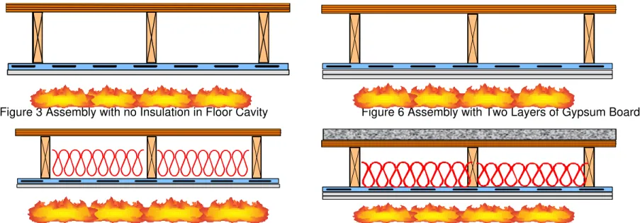
Twenty-two floor assemblies, 4.8 m long by 3.9 m wide, were constructed in accordance with CAN/CSA-A82.31-M919. Floor framing consisted of solid wood joists spanning across the shorter dimension of floor furnace (effective span 3.9 m). All wood joists were nominally, 235 mm deep by 38 mm wide except Assembly 15, which was nominally 184 mm deep by 38 mm wide. The stability of joists was insured by two end wood plates 235 mm deep by 38 mm wide, two wood blocking and cross bracing 19 mm by 64 mm at joists mid-span, and either the plywood or plywood/Gep-Crete sub-floor. In 23 assemblies (see Table 1), resilient channels spaced either 203 mm or 406 mm o.c. or 610 mm o.c., were used and attached perpendicular to joists to support the gypsum board ceiling finish. Additional resilient channels were also installed to support gypsum board ends (board short dimension). The resilient channels, 14 mm deep by 58 mm wide, were fabricated from 0.6 mm thick galvanized steel sheets. The channels had a 34 mm wide web, designed to support the gypsum board connection, and one 18 mm wide flattened flange lip connected to the bottom flanges of the wood joists by 32 mm long screws. Three type of insulation were used: glass and rock fibre batts, 90 mm thick, and cellulose fibre insulation sprayed wet on the underside of the sub-floor and on the side of the joists and allowed to dry to achieve an 11% moisture content or cellulose fibre insulation dry blown and supported at the bottom of the wood joists with steel mesh. The glass, rock and cellulose insulation satisfied CSA A101-M8310, CAN/ULC S702-M9711 and CGSB 51.60-M9012, respectively. The resilient channels and insulation were used for acoustical purposes to reduce the sound transmission across the floor. The sub-floor types used in the assemblies were Canadian Softwood Plywood (CSP) tongue and groove, 15.5 mm or 19 mm thick or CSP deck with, 25.4 mm thick, Gyp-Crete topping. The ceiling finish used in the assemblies was Type X gypsum board, 12.7 mm and 15.9 mm thick. The cross-sections of the floor specimens are illustrated in Figures 3 to 8. The gypsum board (nominal thickness 12.7 mm) used in the floor assemblies had the Firecode C Core Type X” designation and met the requirements of Type X gypsum board13,14. The gypsum boards were supplied from one manufacturer to minimize potential variability associated with the production of such material by different producers. The boards were also packaged (100 boards a patch) to avoid board damage in transportation from the manufacturer to NRCC laboratories. The gypsum boards had an average surface density of 9.85 kg/m2 for a nominal 12.7 mm thick board. The gypsum boards were attached perpendicular to either resilient channels or directly to wood joists; in the case where no resilient channels were used in the assembly, by dry wall Type S screws 41 to 51 mm long, spaced at 300 mm o.c. depending on the number of the gypsum
board layers. Table 1 lists the variable parameters of the assemblies studied. Assemblies 1 and 3 had the gypsum board screws at 10 mm from the board edges while all other assemblies had screws at 38 mm from the edges for the board facing the furnace. Complete construction details can be found in References 2 and 3.
INSTRUMENTATION
The temperature on the unexposed surface for all assemblies was measured at 9 locations in accordance with CAN/ULC-S101-M894. Thermocouples on the unexposed surface were installed under ceramic fibre pads (150 mm wide by 150 mm long by 12.7 mm thick) as per the test method. In addition to the standard instrumentation specified in CAN/ULC-S101-M89, numerous thermocouples were placed within each floor assembly in order to obtain temperature histories at various locations during fire tests. Type K (20 gauge) chromel-alumel thermocouples, with a thickness of 0.91 mm, were used for measuring the temperatures of the sub-floor surface and gypsum board surface facing the floor cavity as well as the interface surface between the gypsum board for assemblies with two layers of gypsum board and between the gypsum board and insulation at the floor cavity side. Also, additional instrumentation to measure the deflection of the sub-floor was used at 9 locations: 3 along the centre line of the assembly and 3 on each side of the centre line at equal spacing. Details on the locations of the thermocouples and deflection gauges can be found in References 2 and 3. Details on the deflection devices used in this study can be found in Reference 15. All floor assemblies were tested with a superimposed load depending on the components of the assembly. Assemblies 1 to 10 were tested using a restricted load of 75% of maximum design load; however, assemblies 9 to 22 were tested on a maximum design load. Details on the loading system arrangement can be found in References 2 and 3. The superimposed load used in this study for each assembly is given in Table 1.
TEST CONDITIONS AND PROCEDURE
The assembly’s gypsum board ceiling finish was exposed to heat in a propane-fired horizontal furnace, shown in Figure 1, in accordance with CAN/ULC-S101-M89, “Standard Methods of Fire Endurance Tests of Building Construction and Materials” which is similar to ASTM E1195 “Standard Test Method for Fire Tests of Building Construction and Materials”. The furnace temperature was measured by nine (20 gauge) shielded thermocouples and the average of these thermocouples was used to control the furnace temperature in such a way that it followed, as closely as possible, the CAN/ULC-S101-M89 standard temperature-time curve.
The assembly was considered to have failed if one of the following failure criteria as per CAN/ULC-S101-M89 Standard, occurred first:
1. A single point temperature reading measured by one of the nine thermocouples under insulation on the unexposed surface rose 180°C above the ambient temperature,
2. The average temperature measured by the 9 thermocouples under the insulated pads on the unexposed surface rose 140°C above the ambient temperature,
3. There was passage of flame or gases hot enough to ignite cotton waste, and 4. The assembly is no longer able to bear the applied load.
RESULTS AND DISCUSSION
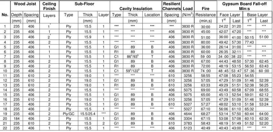
The results of the 22 full-scale fire resistance floor tests are summarised in Table 1 in which the fire resistance and gypsum board layers fall-off time are provided for each assembly. The average temperatures at different surfaces in each assembly, furnace average temperature and three deflection measurements (maximum deflections) at the centre line of the assembly are plotted in Figures 9 to 51. Defection data measured in six other locations can be found in References 2 and 3. The reader should be cautious to the fact that Assemblies 1 to 10 were tested using a restricted load approximately 75% of the maximum design load for a given assembly, however, Assemblies 11 through 22 were tested using a maximum design load.
Gypsum board is a product that provides significant fire resistance protection to building assemblies. It is in a form of sheet product that consists of a non-combustible core, which is at least 75% gypsum with some additives to enhance the fire resistance performance such as glass fibre to reduce the likelihood of crack propagations and vermiculaite to reduce the board shrinkage when exposed to heat, bounded with paper-laminated surfaces. The gypsum core is calcium sulphate dehydrate, CaSO4 .2H2 O, a crystalline mineral that contains about 21% by
weight chemically combined water. In addition, gypsum usually contains a small amount of absorbed free water. As the gypsum is heated to a temperature in excess of 80°C, it begins to undergo a thermal degradation process known as calcinations, in which the chemically combined water dissociates from the crystal lattice. The chemical equation for this process is
CaSO4 .2H2 O → CaSO4 ½ H2 O + 3/2 H2 O
Calcium sulphate hemihydrates (CaSO4 ½ H2 O + 3/2 H2 O) is commonly known as
plaster of Paris. As the gypsum core reaches 125°C, calcinations are usually complete. Through continued heating, the remaining water is released as the hemihydrate undergoes dehydration to form anhydrous calcium sulphate CaSO4.
From the temperature distributions of the assemblies studied, it can be seen that the gypsum board used to protect the floor framing has more or less provided the same trend in temperature, at least in the first 15 - 18 min of fire exposure. Due to this similarity and to avoid repetition in explaining of such behaviour, the gypsum board temperature trend is provided below. However, the behaviour of the gypsum board beyond this period is different depending on the type of assembly components and that will be explained separately for each parameter studied.
When the gypsum board (GWB) ceiling finish is exposed to heat for the first 15 – 18 min, its temperature increases as time goes on. After 3 min of fire exposure, the gypsum board interface surface temperature between the base and face layers at the floor cavity (GWB Face/Base at Cavity) in the case of assemblies with two layers of gypsum board or the gypsum board/insulation interface surface temperature or the gypsum board surface temperature facing the floor cavity for assemblies with either one or two layers of gypsum board rose rapidly to approximately 100°C, where the water in the gypsum board had absorbed its sensible heat and migrated toward the unexposed side. This process is then followed by a gradual temperature rise to approximately 120°C after 15 to18 min due to gypsum board calcinations. At that time, the gypsum board core is almost free from water and thus its temperature rose at a faster rate to approximately 620°C-750°C depending on the assembly components. The effects of different parameters on the fire resistance of floor assemblies are discussed below.
Effect of Gypsum Board Screw spacing from Board Edges
Two cases were studied to investigate the effect of the gypsum board screws spacing from the board edges on the fire resistance: case one, for floor assemblies protected with one layer of Type X gypsum board, and the other for assemblies protected with two layers of Type X gypsum board.
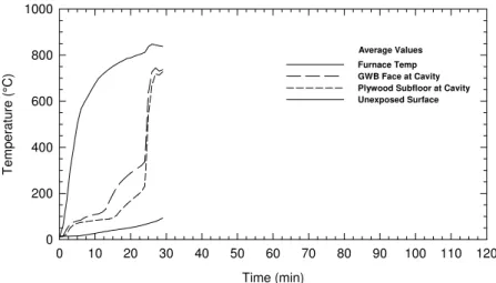
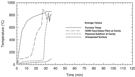
Assemblies 1 and 2 were studied to determine the effect of screws spacing 10 mm vs 38 mm from the board edges in assemblies with one layer of Type X gypsum board. In Assembly 2, resilient channels were used to facilitate the attachment of the gypsum board with screws at 38 mm from the board edges. Design parameters for these assemblies as well as the fall–off time for the gypsum board are provided in Table1. The temperature distributions of the furnace as well as at the gypsum board surface facing the floor cavity (GWB Face at Cavity), plywood surface facing the floor cavity (Plywood Surface at Cavity), and unexposed surface for these assemblies are shown in Figures 9 and 11. Also, the deflection distributions of the plywood sub-floor at three locations along the centre line of the assembly in equal spacing are shown in Figures 10 and 12. The results in Figures 9 and 11 indicate that there was a gradual increase in temperature to 125°C at 13 min in the assembly with screws at 10 mm, and at 15 min in the assembly with screws at 38 mm. At these points of time, the water in the board was driven off and the gypsum board core became dry; consequently, the board edges started to shrink, especially at the vicinity of the screw heads, due in part to a rapid heat transfer from the steel screws to the gypsum board core around them. The board edges peeled away much faster in the assembly with screws at 10 mm, as they were located much closer to the board edges than in the assembly with screws at 38 mm. As the gypsum board edges peeled away, the furnace hot gases penetrated the floor cavity and ignited the wood joists and at that time the gypsum board on both surfaces (furnace side and cavity side) were exposed to furnace heat.
The first piece of gypsum board fell-off much faster (24 min) in the assembly with screws at 10 mm than the assembly with screws at 38 mm (42 min) from the board edges and this occurred when temperature of the gypsum board surface facing the floor cavity was approximately 350°C to 450°C (see Figures 9 and 11) and at this time, the wood joists and the underside of the plywood sub-floor were partly exposed to furnace heat and both the gypsum board surface facing the floor cavity as well as the sub-floor surface facing cavity were measuring a similar temperature with a sharp temperature rise. The sub-floor deflection was approximately 5 mm at the end of the first 20 min in both assemblies; however, this was followed by a sharp increase in the deflection in Assembly 1 and a gradual increase in Assembly 2 due to a loss of the gypsum board protection as well as a decrease in the joist strength caused by the burning of wood joists. Assembly 1 provided 30 min of fire resistance while Assembly 2 provided 45 min of fire resistance. These results showed that by moving the screws further away from the board edges (from 10 mm to 38 mm), the fire resistance had increased by 50%.
Case – 2 Assemblies protected with Two Layers of Type X Gypsum Board
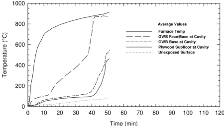
As in Case 1, Assemblies 3 and 4 (with screws at 10 mm and 38 mm from the board edges, respectively) were studied to investigate the effect of screws spacing from the board edges in assemblies with two layers of Type X gypsum board. Resilient channels were used in both cases but they were doubled at the board joints in Assembly 4 to allow screws to be located at 38 mm from the board edges. In Assembly 3, with screws at 10 mm, the first gypsum board face and base layer fell-off from the assembly at 36 min and 50 min, respectively. This occurred when the temperature of the gypsum board interface surface (GWB Face/base) was approximately at 550°C (see Figure 13). In Assembly 4, with screws located at 38 mm, the first piece of the gypsum board face and base layer had dropped at approximately 49 min and 78 min, respectively, where the gypsum board interface temperature between the face and base layer was at 700°C. Thus, the sub-floor and the joist sides were exposed to the furnace heat much earlier in Assembly 3 than in Assembly 4 due to the early fall-off of the gypsum board. The sub-floor deflection was 5 mm at 50 min in both assemblies; however, in Assembly 4 this was followed by a gradual deflection and then by a sudden defection at 80 min where a flame appeared on the unexposed sub-floor surface. Assemblies 3 and 4 provided 51 min and 80 min fire resistance, respectively. From these results, the assembly with screws located at 38 mm from the board edges provided 57% more fire resistance compared to an assembly with screws at 10 mm.
The results of the two cases studied above for assemblies with one and two layers of gypsum board, showed that the effect of the screws location from the board edges on the fire resistance is significant.
Effect of Insulation Installation and Type
Two cases were studied to investigate the effects of insulation installation and type on the fire resistance in floor assemblies protected with either one or two layers of Type X gypsum board.
Assemblies 2 (no insulation), 5 (with glass fibre insulation), 6 (with rock fibre insulation), and 7 (with cellulose fibre insulation sprayed wet) were studied to investigate the effect of the insulation installation and type on the fire resistance performance of wood joist floor assemblies with one layer of Type X gypsum board. The gypsum board fall-off time for these assemblies is provided in Table 1 and the temperature and deflection measurements are shown in Figures 11, 12, 17 to 22.
The results shown in Figures 11, 17, 19 and 21, for insulated and non-insulated assemblies indicate that the temperature began to increase on the gypsum board at the cavity side approximately 2 min after the experiment was started and the rate of temperature increase was faster in the assemblies with insulation in the cavity than in a non-insulated assembly. This was followed by a gradual increase in temperature to 125 °C at 8 to 15 min and, after that time, the temperature increase was substantially higher at the gypsum board surface on the cavity side for insulated assemblies than a non-insulated assembly as reported above. As a result of the substantial increase in board temperature (approximately at 26 min for assemblies with either glass or rock fibre insulation and at 38 min for assembly with cellulose fibre insulation where temperature on the gypsum board facing cavity was 450°C and 650°C for non insulated and insulated assemblies, respectively), the board cracked and fell-off faster in insulated assemblies than in a non-insulated assembly. This is due to the presence of an additional thermal resistance caused by the installation of insulation in the floor cavity. However, in the assembly with glass fibre insulation, the fibre melted when it was exposed to furnace heat for about 2 to 3 min after the gypsum board had fallen from the assembly; consequently, the sub-floor and wood joist sides were burning due to the exposure to furnace heat. Thus, the glass fibre was unable to compensate for the earlier failure of the gypsum board and provided a negative effect in the fire resistance compared to a non-insulated assembly. The rock and cellulose fibre shrank slightly and remained in place after the gypsum board fall-off and they were able to compensate for the early failure of the gypsum board as well to protect the joists and the sub-floor from the furnace heat, thus, both rock and cellulose fibre insulation provided a positive effect on the fire resistance compared to a non-insulated assembly. The deflection results shown in Figures 12, 18, 20 and 22, showed that, there is about a 5 mm deflection in these assemblies prior to the fall-off of the gypsum board, however, afterward in assemblies with insulation, the deflection was higher in the assembly with glass fibre and lower in the assemblies with rock and cellulose fibre compared to a non-insulated assembly. This was due to the early fall-off of the gypsum board and melting of the glass fibre insulation and
stay-in-place for the rock and cellulose fibre insulation. The results showed that, compared to a non-insulated assembly, which provided 45 min of fire resistance, the installation of the glass fibre reduced the fire resistance by 20% while the installation of either the rock and cellulose fibre increased the fire resistance by 33% and 31%, respectively.
Case – 2 Assemblies with Two Layers of Gypsum Board
Three groups of assemblies were studied in this case to investigate the effect of insulation installation and type in a floor cavity on the fire resistance for assemblies with two layers of gypsum board: In Group 1, assemblies were tested with restricted superimposed loads using joists and resilient channels spaced at 406 mm o.c., while in Group 2, assemblies were tested with maximum design superimposed loads using joists and resilient channels spaced at 610 mm o.c. In Group 3, assemblies were tested with maximum design loads using joists and resilient channels spaced at 406 mm o.c. and only glass fibre insulation.
Group – 1 Assemblies with restricted superimposed load
In Group 1, Assembly 4 (no insulation), Assembly 8 (glass fibre), Assembly 9 (rock fibre insulation), Assembly 10 (cellulose fibre insulation sprayed wet) were studied to investigate the effect of the insulation installation and type on the fire resistance performance of floor assemblies with wood joists and resilient channels spaced at 406 mm o.c. and protected with two layers of Type X gypsum board. The gypsum board fall-off time for these assemblies is given in Table 1. The average temperature of different surfaces and deflection measurements at the centre line for these assemblies are shown in Figures 15, 16 and 23 to 28.
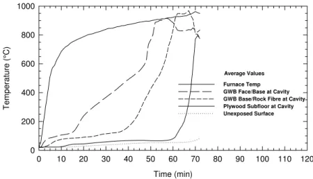
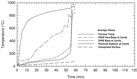
The first piece of gypsum board face layer for a non-insulated assembly had dropped at 50 min while with insulated assemblies the first piece dropped at approximately 45 min to 49 min. The gypsum board interface temperature between the gypsum board face and base layers (GWB Face/Base at cavity) was at approximately 600°C. The first piece of the gypsum board base layer for a non-insulated assembly had dropped at 78 min while with insulated assemblies it dropped at approximately 57 min. The gypsum board surface temperature-facing cavity for a non-insulated assembly (GWB Base at cavity) was at 500°C. In insulated assemblies the temperature between the gypsum board base layer and insulation (GWB Base/Glass or Rock fibre at cavity) was at approximately 600°C for glass and rock fibre insulation and at 500°C for an assembly with cellulose fibre insulation.
The temperature results shown in Figures 15, 23, 25 and 27, indicate that unlike the assemblies with one layer of gypsum board, the gypsum board interface temperature between the face and base layers (GWB Face/Base at cavity) has the same trend for insulated and non-insulated assemblies. The presence of insulation in the floor cavity did not affect the fire resistance performance of the gypsum board base layer as the gypsum board face layer still absorbs heat from the gypsum board face layer. However, the interface temperature between the gypsum board base layer and insulation for assemblies with glass and rock fibre insulation is similar but somewhat higher than the gypsum board surface temperature-facing cavity in a non-insulated assembly. This could be explained by the additional thermal resistance caused by the installation of insulation above the gypsum board. For the assembly with cellulose fibre insulation where the insulation was sprayed on the underside of the sub-floor, there was an air cavity above the gypsum board base layer. The gypsum board base layer surface temperature facing the cavity was similar for both assemblies with no insulation and with cellulose insulation for up to 40 min, however afterward, the latter assembly had a higher temperature than the former assembly with no insulation in the cavity and this was due to the additional thermal resistance caused by the installation of cellulose fibre insulation.
The deflection results shown in Figures 16, 24, 26 and 28 indicate that the sub-floor attached to the wood joist had a little deflection (5 mm) prior the fall-off of the gypsum board base layer (1st line of defence for fire resistance), however afterward, the deflection of the sub-floor was higher in insulated assemblies than in a non-insulated assembly due to the degradation of insulation (2nd line of defence for fire resistance) and burning of wood joists.
Assemblies 41 (no insulation), 8 (with glass fibre), 9 (with rock fibre) and 10 (with cellulose fibre) provided 80 min, 67 min, 72 min and 74 min fire resistance, respectively. These results indicate that the installation of the insulation in the floor cavity for assemblies with two layers of gypsum board and tested on a restricted load (75% of maximum load) reduced the fire resistance by 16% for glass, 10% for rock and 8% for cellulose compared to a non-insulated assembly. These results are not consistent with those assemblies protected with one layer of gypsum board where the rock and cellulose fibre insulation provided a positive effect on the fire resistance compared to a non-insulated assembly. This could be explained as the heat exposure time for indirect furnace heat (conduction via the face and base layers) was much longer in assemblies with two layers of gypsum board than in an insulated assembly with one layer of gypsum board, the three insulation types were more deteriorated when the board fell-off
from the assembly and were unable to compensate for the earlier failure of the gypsum board. For this reason, the deteriorated glass, rock and cellulose fibre insulations provided a negative effect on the fire resistance compared to a non-insulated assembly.
In Group 2, using maximum design load, Assemblies 11 (no insulation), 12 (glass fibre insulation) and 13 (rock fibre) were studied to investigate the effect of the insulation installation and type on the fire resistance performance of floor assemblies with wood joists and resilient channels spaced at 610 mm o.c. and protected with two layers of Type X gypsum board. The temperature and deflection measurements for these assemblies are shown in Figures 29 to 34.
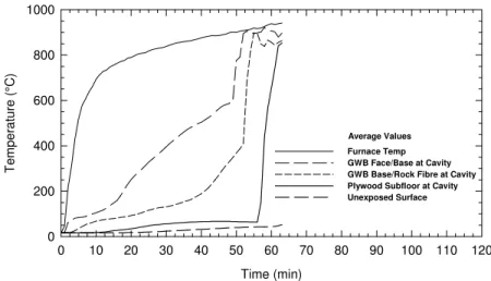
The first piece of gypsum board face layer fell-off at approximately 47 to 49 min for insulated and non-insulated assemblies in which the gypsum board interface temperature (GWB Face/Base at Cavity) was approximately 600°C. The first piece of the gypsum board base layer had dropped at 53 to 55 min in which the gypsum board surface temperature at the cavity side (GWB Base at Cavity) was at 450°C for the non-insulated assembly and was approximately at 550°C for insulated assemblies. In the assembly with glass fibre insulation, as the gypsum board based layer dropped, the glass fibre was exposed to furnace heat and consequently melted and dropped like a shower from the assembly in about 2 to 3 min. At that time, the joists and sub-floor were also exposed to furnace heat. In the assembly with rock fibre, the insulation did not melt but sagged and furnace hot gases also penetrated and heated up the floor cavity.
The temperature measurement results shown in Figures 29, 31 and 33, for non-insulated and insulated assemblies indicate that, the gypsum board interface temperature between the face and base layers (GWB Face/Base at cavity) has the same trend for insulated and non-insulated assemblies while the interface temperature between the gypsum board and either glass or rock fibre insulation has similar distribution but is somewhat higher than in the assembly with no insulation. As explained in Group 1 above, this could be due to the added thermal resistance caused by the installation of insulation.
The deflection measurements shown in Figures 30, 32 and 34, indicate that the sub-floor had a little deflection (5 mm) prior to the fall-off of the gypsum board base layer, however, this was followed by a gradual deflection and ended by a sudden deflection at the failure time. This trend is similar to the results shown in Group 1 mentioned-above.
Assemblies 11 (No insulation), 12 (glass fibre) and 13 (rock fibre) provided 58 min 55 s, 57 min 5 s and 63 min 33 s fire resistance, respectively. These results indicate that unlike Group 1 above where resilient channels spaced at 406 mm o.c. and assemblies tested using a restricted load, this Group 2, the resilient channels spaced at 610 mm o.c. and tested on a maximum design load, the glass fibre insulation had reduced slightly (3%) the fire resistance while the rock fibre had increased slightly (7%) the fire resistance compared to a non-insulated assembly. The difference in the fire resistance performance of a rock fibre insulation performance compared to a non-insulated assembly in assemblies tested using restricted and maximum design load could be caused by a longer fire exposure and more deterioration for the rock insulation when the assembly tested using a restricted load.
Group 3 is the same as Group 2 except that the joists and resilient channels were spaced at 406 mm o.c. Assembly 14 with no insulation and Assembly 15 with glass fibre insulation were studied to investigate the effect of glass fibre insulation installation on the fire resistance performance of assemblies with two layers of Type X gypsum board. The gypsum board fall-off time for these assemblies is given in Table 1. The average temperature of different surface and deflection measurements at the centre line for these assemblies are shown in Figures 34 to 37.
The first piece of gypsum board face layer had dropped at approximately 44 min for a non-insulated assembly and at 45 min for an insulated assembly. The gypsum board interface temperature between the gypsum board face and base layers (GWB Face/Base at cavity) was at approximately 600°C. The first piece of the gypsum board base layer had dropped at approximately 67 min with a non-insulated assembly and at 59 min with an insulated assembly. The gypsum board surface temperature facing the cavity was at approximately 550°C in an insulated assembly and at approximately 750°C for a non-insulated assembly.
The temperature results shown in Figures 34 and 36 indicate that the gypsum board interface layer between the face and base layers (GWB Face/Base at cavity) has the same distribution trend for an insulated and non-insulated assemblies and also as mentioned above for Groups 1 and 2, the presence of insulation did not affect the fire resistance performance of the gypsum board face layer. However, the gypsum board interface temperature for insulated assembly (GWB/Glass Fibre at cavity) was higher than the gypsum board base layer surface facing cavity and as explained before in Groups 1 and 2, this could be due to the added thermal
resistance caused by the installation of glass fibre insulation above the gypsum board base layer.
The deflection measurements shown in Figures 35 and 37 indicate that the sub-floor attached to the joists had little deflection prior to the fall-off of gypsum board; however, deflection was gradually increasing due to the deterioration of the joist’s strength that was caused by the melting of the glass fibre and burning wood joists.
The assembly with no insulation provided 69 min and an assembly with insulation provided 65 min of fire resistance, therefore, the installation of glass fibre insulation has reduced the fire resistance by 6% compared to an assembly with no insulation in a floor cavity and this is consistent with results in Groups 1 and 2 above.
The presence of glass fibre insulation reduced the fire resistance for both the 75% and 100% load cases. Rock and cellulode fibre also reduced the fire resistance in 75% load case. However, when compared with a non-insulated floor, rock fibre slightely increased fire resistance in the 100% load case.
Effect of Joists Spacing
Assemblies 16 and 17 were studied to investigate the effects of the wood joist spacing (610 mm o.c. and 406 mm o.c., respectively) on the fire resistance of assemblies with two layers of Type X gypsum board attached to resilient channels spaced at 610 mm o.c. and glass fibre insulation placed on the resilient channels above the gypsum board between the joists. The gypsum board fall-off time for these assemblies is given in Table 1. The temperature and deflection distributions for these assemblies are shown in Figures 38 to 41.
The first piece of gypsum board face layer to fall off with assemblies 16 and 17 dropped at at approximately the same time, 48 min, when the gypsum board interface temperature between the face and base layers was at approximately 600°C. The gypsum board base layer for both assemblies had also dropped at the same time at approximately 52 min where the gypsum board interface temperature between the base layer and insulation was at approximately 500°C.
The temperature results shown in Figures 38 and 40 indicate that the temperature distribution trend for both interface between the face and base layer and between the base layer and insulation is more or less similar for both assemblies. Also the deflection distribution trend shown in Figures 39 and 41 is similar. Assembly 16 provided 57 min 5 s and Assembly 17 provided 57 min 27 s. These results showed that the effect of joist spacing on the fire resistance performance is insignificant as the gypsum board was attached to resilient channels of the same spacing, 610 mm o.c. and not to the joists. The difference in the fire resistance results would be significant if the gypsum board was attached directly to the joists of different spacing and this is due to the use of fewer screws to attach the gypsum board to the joists joist spacing of 600 mm o.c. but this case was considered in this study. However, in the section below that discusses the effect of resilient channels spacing in this paper, the reader will see the effect of having fewer screws to attach the gypsum board to resilient channels of different spacing on the fire resistance.
Effect of Resilient Channels Installation
Assembly 18 (with resilient channels) and Assembly 14 (without resilient channels) were studied to determine the effect of resilient channels installation on the fire resistance of assemblies with two layers of Type X gypsum board and no insulation in the floor cavity. The gypsum board fall-off time for these assemblies is given in Table 1. The temperature distribution at different surfaces and sub-floor deflection for both assemblies are shown in Figures 34, 35, 42 and 43.
In Assembly 14, the first piece of the face layer gypsum board dropped at 44 min while with Assembly 16 it dropped at 56 min when the gypsum board interface between the face and base layers was at approximately 600°C. The first piece of the gypsum board base layer dropped at 65 min with Assembly 18 and at 67 min with Assembly 14 when the gypsum board surface temperature-facing cavity was approximately at 550°C in Assembly 14 and at 400°C in Assembly 18.
The temperature distribution shown in Figures 34 and 42 indicate that the gypsum board interface temperature between the face and base layer (GWB Face/Base at Cavity) had more or less a similar trend. The deflection distribution shown in Figures 35 and 43 indicate that the sub-floor attached to the joist had a little deflection (5 mm) prior to the fall-off of the gypsum
board; however, afterward, the deflection was gradual in both assemblies until the structure failure of the assembly.
Assembly 14 with the gypsum board attached to resilient channels spaced at 406 mm o.c. provided 69 min of fire resistance while Assembly 18 with the gypsum board attached to the wood joists spaced at 406 mm o.c. provided 67 min 10 s. These results showed that the effect of resilient channel installation on the fire resistance performance of floor assembly with two layers of Type X gypsum board is insignificant. This is a very useful finding as the installation of resilient channels in the assembly improves the sound reduction across it and at the same time it does not have an impact on the fire resistance of the assembly.
Effect of Resilient Channel Spacing
Two experiments were conducted to study the effect of resilient channel spacing on the fire resistance of assemblies with two layers with Type X gypsum board, glass fibre insulation in the floor cavity and a plywood sub-floor. Assembly 15 was with resilient channels spaced at 406 mm o.c. and Assembly17 was with resilient channels spaced at 610 mm o.c. The gypsum board fall-off time for these assemblies is given in Table 1. The temperature distribution at different surfaces and the sub-floor deflection for both assemblies are shown in Figures 36, 37, 40 and 41. The first piece of the gypsum board face layer to fall with Assemblies 15 and 17 dropped at approximately 45 min and 48 min, respectively. The first piece of the base layer gypsum board to fall with Assemblies 15 and 17 dropped at 59 min and 52 min respectively. Assembly 15 with resilient channels spaced at 406 mm o.c. provided 65 min of fire resistance while Assembly 17 with resilient channels spaced at 610 mm o.c. provided 57 min 27 s of fire resistance. These results showed that the latter assembly with a wider resilient channels spacing provided 12% less fire resistance than the former assembly with a shorter resilient channels spacing. This difference in fire resistance performance could be due to the use of more screws in the assembly with shorter resilient channel spacing, where the gypsum board base layer remained in place longer, than in an assembly with wider resilient channel spacing.
Effect of Sub-Floor Topping
Assemblies 15 and 19 were studied to investigate the effect of adding Gyp-Crete (mix of concrete and gypsum) topping above the plywood sub-floor on the fire resistance in floor assemblies with two layers of Type X gypsum board, glass fibre insulation in the floor cavity and
a plywood sub-floor. The gypsum board fall-off time for these assemblies is given in Table 1. The temperature distributions at different surfaces and sub-floor deflection for both assemblies are shown in Figures 36, 37, 44 and 45. The first piece of the gypsum board face layer dropped faster in the assembly with no Gyp-Crete topping than in the assembly with Gyp-Crete topping; this could be due to the heat sink caused by the installation of Gyp-Crete above the plywood sub-floor, however the first piece of the gypsum board base layer dropped within approximately two minutes of each other. In these assemblies, the interface temperature between the gypsum board face and base layer (GWB Face/Base at Cavity) as well as between the gypsum board base and glass fibre insulation (GWB Base/Glass Fibre at cavity) was more or less similar up to 40 min and that was followed by a higher temperature in the assembly with no Gyp-Crete topping due to the heat sink caused by the installation of Gyp-Crete layer as explained above. The deflection was also more or less similar in both assemblies up to the failure of the assembly. Assemblies 15 and 19 provided 65 min and 68 min 27 s fire resistance, respectively. The assembly with Gyp-Crete topping provided slightly 5% more fire resistance compared to a similar assembly with no topping. This difference in fire resistance can be considered insignificant.
Effect of Joist Depth
Assemblies 15 (235 mm deep by 38 mm wide) and 20 (184 mm deep by 38 mm wide) were studied to investigate the effect of wood joist depth on the fire resistance in floor assemblies with two layers of Type X gypsum board, glass fibre insulation in the floor cavity and a plywood sub-floor. The gypsum board fall-off time for these assemblies is given in Table 1. The temperature distributions at different surfaces and sub-floor deflection for both assemblies are shown in Figures 36, 37, 46 and 47. The first piece of the gypsum board base layer dropped within one minute of each other in both assemblies. The deflection was also more or less similar in both assemblies up to the failure of the assembly. Assemblies 15 and 20 provided 65 min and 67 min 15 s fire resistance, respectively. The assembly with the smaller joist depth provided slightly 3% more fire resistance compared to a similar assembly but with bigger joist depth. This difference in fire resistance for the joist depth studied (235 mm vs 184 mm) can be considered insignificant.
Assemblies 16 (one layer) and 21 (two layers) were studied to investigate the effect of the number of plywood sub-floor layers on the fire resistance in floor assemblies with two layers of Type X gypsum board and glass fibre insulation in floor cavity. The gypsum board fall-off time for these assemblies is given in Table 1. The temperature distributions at different surfaces and sub-floor deflection for both assemblies are shown in Figures 38, 39, 48 and 49. The first piece of the gypsum board face and base layers for both assemblies had dropped approximately at the same time. In these assemblies, the interface temperature between the gypsum board face and base layer (GWB Face/Base at Cavity) as well as between the gypsum board base and glass fibre insulation (GWB Base/Glass Fibre at cavity) was more or less similar for both assemblies. The deflection was also more or less similar in both assemblies up to the failure of the assembly. Assemblies 16 and 21 provided 57 min 5 s and 58 min 43 s fire resistance, respectively. This difference in fire resistance is insignificant.
Effect of Superimposed Load Magnitude
Assemblies 2 with 75% design load (restricted load) and 22 with 100% design load were studied to investigate the effect of load magnitude on the fire resistance of a floor assembly with one layer of Type X gypsum board, wood joist and resilient channels spaced at 406 mm o.c. and no insulation in the floor cavity. The gypsum board fall-off time for these assemblies is given in Table 1. The temperature distributions at different surfaces and sub-floor deflection for both assemblies are shown in Figures 11, 12, 50 and 51. The first piece of the gypsum board layer for both assemblies dropped at approximately the same time. In these assemblies, the gypsum board surface temperature facing floor cavity (GWB Face at Cavity) was more or less similar for both assemblies. The deflection was also more or less similar in both assemblies up to the failure of the assembly. Assemblies 2 and 22 provided 45 min and 40 min 49 s fire resistance, respectively. These results showed that the fire resistance decreases with the increase in the superimposed load.
CONCLUSIONS
In this paper, the results of twenty-two full-scale fire resistance tests conducted to investigate the impact of various parameters on the fire resistance of lightweight frame floor assemblies have been presented. Based on the results of the tests, the following key findings can be drawn:
1. For floor assemblies protected with either one or two layers of Type X gypsum board, moving the drywall screws from 10 mm to 38 mm from the board edges increased the fire resistance of the assembly by up to 57%.
2. In a floor assembly protected with one layer of Type X gypsum board, the installation of glass fibre reduced the fire resistance by 20% while the installation of either rock fibre or cellulose fibre increased the fire resistance by 33% and 31%, respectively.
3. For floor assemblies protected with two layers of Type X gypsum board:
• The installation of insulation in a floor cavity using a restricted load of 75% maximum design load reduced the fire resistance by 16% for glass fibre, 10% for rock fibre and 8% for cellulose fibre compared to a non-insulated assembly. • The effects of insulation installation, joist spacing (406 mm vs 610 mm) where
the gypsum board is attached to resilient channels of the same spacing, joist depth (235 mm vs 184 mm), resilient channels installation, adding Gyp-Crete topping on the sub-floor and a number of plywood sub-floor layers (one vs two) on the fire resistance are insignificant.
• The use of a wider resilient channel spaced at 610 mm o.c. provided 12% less fire resistance than the use of a shorter resilient channel spaced at 406 mm o.c. • The fire resistance decreased with the increase of the superimposed load.
ACKNOWLEDGEMENTS
The National Research Council of Canada wishes to acknowledge the technical and financial contributions of the partners in this Joint Research Project. The partners include: Boise Cascade, Canada Mortgage and Housing Corporation, Canadian Home Builder Association, Canadian Portland Cement Association, Canadian Sheet Steel Building Institute, Canadian Steel Construction Council, Canadian Wood Council, Cellulose Insulation Manufacturers’ Association of Canada, Forintek Canada Corporation, US Gypsum Association, Gypsum Manufacturers’ of Canada, Louisiana-Pacific Corporation, Nascor Inc., Ontario Home Warranty Program, Ontario Ministry of Municipal Affairs and Housing, Truss Plate Institute, Truss Plate Institute of Canada, US Cellulose Manufacturers Association, Johns Manville International, Owens-Corning Canada, Willamette Industries, Roxul Inc., Trus Joist MacMillan.
Also, the author wishes to thank Jocelyn Henrie, John Latour, Patrice Leroux, Rock Monette and Richard Rombough for construction the assemblies and conducting the experiments.
REFERENCES
1. National Building Code of Canada (Part 9), National Research Council of Canada, Ottawa, ON, 1995.
2. Sultan, M.A., Seguin, Y.P., Leroux, Results of Fire Resistance Tests on Full-Scale Floor Assemblies, Internal Report No. 764, Institute for Research in Construction, National Research Council of Canada, Ottawa, ON, 1998.
3. Sultan, M.A, Latour, J.C., Leroux, P., Monette, R.C., Seguin, Y.P. and Henrie, J. « Results of Fire Resistance Tests on Full-scale Floor Assemblies – Phase II », Research Report 184, Institute for Research in Construction, National Research Council Canada, Ottawa, Ontario, 2005.
4. CAN/ULC-S101-M89, Standard Methods of Fire Endurance Tests of Building Construction and Materials. Underwriters' Laboratories of Canada, Scarborough, ON, 1989.
5. ASTM E119-88, Standard Test Method for Fire Tests of Building Construction and Materials, ASTM, West Conshohocken, PA, 1988.
6. National Building Code of Canada (Part 9), National Research Council of Canada, Ottawa, ON, 2005.
7. Benichou, Noureddine, Structural Response Modelling of Wood Joist Floor Assemblies Exposed to Fires, Proceedings of the 10th international Fire Science & Engineering Conference (Interflam2004), Edinburgh, Scotland, Interscience Communications Ltd, West Yard House, Guildford Grove, Greenwich, London SE10 8JT, England, 2004.
8. Richardson, L, Failure of Floor Assemblies Constructed with Timer Joists, Wood Trusses or I-joists During Fire Resistance Tests, Proceedings of the 10th international Fire Science & Engineering Conference (Interflam2004), Edinburgh, Scotland, Interscience Communications Ltd, West Yard House, Guildford Grove, Greenwich, London SE10 8JT, England, 2004.
9. CAN/CSA-A82.31-M91, Gypsum Board Application, Canadian Standards Association, Rexdale, ON, 1991.
10. CSA A101-M83, Thermal Insulation, Canadian Standards Association, Rexdale, Ontario, 1983.
11. CAN/ULC-S702-M97, Standard for Mineral Fibre Thermal Insulation for Buildings, Underwriters’ Laboratories of Canada, Scarborough, Ontario, 1997.
12. CAN/CGSB 51.60-M90, Cellulose Fibre Loose Fill Thermal Insulation, Canadian Standards Board, Ottawa, Ontario, 1990.
13. CAN/CSA-82.27-M91, Gypsum Board, Canadian Standards Association, Etobicoke, Ontario, Canada, 1991.
14. ASTM C36-97, Standard Specification for Gypsum Wallboard, American Society for Testing and Materials, West Conshohocken, PA, June 1997.
15. Shorter, G.W. and Harmathy, T.Z., Fire Research Furnaces at the National Research Council, NRC 5732, National Research Council of Canada, Ottawa, Ontario, 1960.
No. Depth Spacing Type Thick Layer Type Thick Location Spacing (N/m ) Resistance Face Layer Base Layer (mm) (mm)
Layers
(mm) (mm) (mm) (min,s) 1st Last 1st Last
1 235 406 1* Ply 15.5 1 *** *** *** *** 3830 R 30:00 24:22 31:20 *** *** 2 235 406 1 Ply 15.5 1 *** *** *** 406 3830 R 45:00 42:07 47:20 *** *** 3 235 406 2* Ply 15.9 1 *** *** *** 406 3830 R 51:00 36:00 41:00 50:15 51:00 4 235 406 2 Ply 15.5 1 *** *** *** 406 3830 R 80:00 49:42 57:30 77:43 5 235 406 1 Ply 15.5 1 G1 89 B 406 3830 R 36:00 26:14 31:00 *** *** 6 235 406 1 Ply 15.5 1 R1 89 B 406 3830 R 60:00 26:35 32:11 *** *** 7 235 406 1 Ply 15.5 1 C1 86a/93b T 406 3830 R 59 :00 34 :00 38 :22 *** *** 8 235 406 2 Ply 15.5 1 G1 89 B 406 3830 R 67:00 44:43 48:50 57:30 62:45 9 235 406 2 Ply 15.5 1 R1 89 B 406 3830 R 72:00 48:19 53:15 56:50 63:43 10 235 406 2 Ply 15.5 1 C1 59a/122b T 406 3830 R 74 :00 48 :45 53 :47 57 :36 60 :00 11 235 610 2 Ply 19.0 1 *** *** *** 610 3256 58:55 47:08 55:23 54:55 12 235 610 2 Ply 19.0 1 G1 89 B 610 3256 57:05 47:29 51:09 51:46 52:39 13 235 610 2 Ply 19.0 1 R1 89 B 610 3256 63:33 49:29 51:51 52:38 56:25 14 235 406 2 Ply 15.5 1 *** *** *** 406 5075 69:00 43:49 60:58 67:09 68:55 15 235 406 2 Ply 15.5 1 G1 89 B 406 5075 65:00 45:13 52:54 59:01 62:12 16 235 610 2 Ply 19.0 1 G1 89 B 610 3256 57:05 47:29 51:09 51:46 52:39 17 235 406 2 Ply 15.5 1 G1 89 B 610 5027 57:27 48:02 53:10 51:58 53:24 18 235 406 2 Ply 15.5 1 *** *** *** *** 5027 67:10 56:06 61:10 65:32 19 235 406 2 Ply/GC 15.5/25.4 *** G1 89 B 406 4644 68:27 53:14 57:50 60:44 64:00 20 184 406 2 Ply 15.5 1 G1 89 B 406 3304 67:15 53:08 57:08 60:10 62:30 21 235 610 2 Ply 15.5 2 G1 89 B 610 3783 58:43 48:19 51:49 51:52 52:20 22 235 406 1 Ply 15.5 1 *** *** *** 406 5123 40:49 40:43 43:00 *** *** Legend:
R1 - Rock fibre insulation batts *** - Null Value C1 - Cellulose fibre insulation, wet sprayed Ply – Plywood
G1 – Glass fibre Insulation a – Thickness of cellulose fibre on underside of sub-floor Ply/GC – Gyp-Crete on plywood b – Thickness of cellulose fibre on wood joist sides B – Insulation on top of gypsum board S – Structural Failure
T – Insulation sprayed on underside of sub-floor and side of joists F – Flame penetration through sub-floor R – Restricted load (75% design load) Gypsum board used was 12.7 mm thick C – Plywood thickness
D – Gyp-Crete thickness
* - Screws at 10 mm from board edges
Figure 3 Assembly with no Insulation in Floor Cavity Figure 6 Assembly with Two Layers of Gypsum Board
Figure 4 Assembly with either Glass or Rock Fibre Insulation Figure 7 Assembly with Plywood Deck and Gyp-crete Topping
Figure 5 Assembly with Cellulose fibre insulation sprayed wet Figure 8 Assembly with full cavity filled with dry Cellulose fibre
Time (min) 0 10 20 30 40 50 60 70 80 90 100 110 120 T e m p e rat ure (°C) 0 200 400 600 800 1000 Furnace Temp GWB Face at Cavity Plywood Subfloor at Cavity Unexposed Surface Average Values Time (min) 0 10 20 30 40 50 60 70 80 90 100 110 120 130 Deflection ( c m ) -30 -25 -20 -15 -10 -5 0
North Joist Deflection Centre Joist Deflection South Joist Deflection
Figure 9 Temperature Distribution (Assembly 1) Figure 10 Deflection Distribution (Assembly 1)
Time (min) 0 10 20 30 40 50 60 70 80 90 100 110 120 T e m p e rat ure (°C) 0 200 400 600 800 1000 Furnace Temp GWB Face at Cavity Plywood Subfloor at Cavity Unexposed Surface Average Values Time (min) 0 10 20 30 40 50 60 70 80 90 100 110 120 130 Def lec ti on (c m) -30 -25 -20 -15 -10 -5 0
North Joist Deflection Centre Joist Deflection South Joist Deflection
Time (min) 0 10 20 30 40 50 60 70 80 90 100 110 120 Te mpe rat ur e ( °C ) 0 200 400 600 800 1000 Furnace Temp GWB Face/Base at Cavity GWB Base at Cavity Plywood Subfloor at Cavity Unexposed Surface Average Values Time (min) 0 10 20 30 40 50 60 70 80 90 100 110 120 130 Def lec ti on (c m) -30 -25 -20 -15 -10 -5 0
North Joist Deflection Centre Joist Deflection South Joist Deflection
Figure 13 Temperature Distribution (Assembly 3) Figure 14 Deflection Distribution (Assembly 3)
Time (min) 0 10 20 30 40 50 60 70 80 90 100 110 120 T e m p e rat ure (°C) 0 200 400 600 800 1000 Furnace Temp GWB Face/Base at Cavity GWB Base at Cavity Plywood Subfloor at Cavity Unexposed Surface Average Values Time (min) 0 10 20 30 40 50 60 70 80 90 100 110 120 130 Def lec ti on (c m) -30 -25 -20 -15 -10 -5 0
North Joist Deflection Centre Joist Deflection South Joist Deflection
Time (min) 0 10 20 30 40 50 60 70 80 90 100 110 120 T e m p e rat ure (°C) 0 200 400 600 800 1000 Furnace Temp
GWB Face/Glass Fibre at Cavity Plywood Subfloor at Cavity Unexposed Surface Average Values Time (min) 0 10 20 30 40 50 60 70 80 90 100 110 120 130 Def lec ti on (c m) -30 -25 -20 -15 -10 -5 0
North Joist Deflection Centre Joist Deflection South Joist Deflection
Figure 17 Temperature Distribution (Assembly 5) Figure 18 Deflection Distribution (Assembly 5)
Time (min) 0 10 20 30 40 50 60 70 80 90 100 110 120 T e mp er at ur e ( °C ) 0 200 400 600 800 1000 Furnace Temp
GWB Face/Rock Fibre at Cavity Plywood Subfloor at Cavity Unexposed Surface Average Values Time (min) 0 10 20 30 40 50 60 70 80 90 100 110 120 130 Def lec ti on (c m) -30 -25 -20 -15 -10 -5 0
North Joist Deflection Centre Joist Deflection South Joist Deflection
Time (min) 0 10 20 30 40 50 60 70 80 90 100 110 120 T e m p e rat ure (°C) 0 200 400 600 800 1000 Furnace Temp GWB Face at Cavity
Cellulose Fibre/Subfloor at Cavity Unexposed Surface Average Values Time (min) 0 10 20 30 40 50 60 70 80 90 100 110 120 130 Def lec ti on (c m) -30 -25 -20 -15 -10 -5 0
North Joist Deflection Centre Joist Deflection South Joist Deflection
Figure 21 Temperature Distribution (Assembly 7) Figure 22 Deflection Distribution (Assembly 7)
Time (min) 0 10 20 30 40 50 60 70 80 90 100 110 120 T e m p e rat ure (°C) 0 200 400 600 800 1000 Furnace Temp GWB Face/Base at Cavity GWB Base/Glass Fibre at Cavity Plywood Subfloor at Cavity Unexposed Surface Average Values Time (min) 0 10 20 30 40 50 60 70 80 90 100 110 120 130 Def lec ti on (c m) -30 -25 -20 -15 -10 -5 0
North Joist Deflection Centre Joist Deflection South Joist Deflection
Time (min) 0 10 20 30 40 50 60 70 80 90 100 110 120 Te mpe rat ur e ( °C ) 0 200 400 600 800 1000 Furnace Temp GWB Face/Base at Cavity GWB Base/Rock Fibre at Cavity Plywood Subfloor at Cavity Unexposed Surface Average Values Time (min) 0 10 20 30 40 50 60 70 80 90 100 110 120 130 Def le c tion ( c m) -14 -12 -10 -8 -6 -4 -2 0 2
North Joist Deflection Centre Joist Deflection South Joist Deflection
Figure 25 Temperature Distribution (Assembly 9) Figure 26 Deflection Distribution (Assembly 8)
Time (min) 0 10 20 30 40 50 60 70 80 90 100 110 120 T e m p erat u re (°C) 0 200 400 600 800 1000 Furnace Temp GWB Face/Base at Cavity GWB Base at Cavity Cellulose Fibre/Subfloor at Cavirt Unexposed Surface Average Values Time (min) 0 10 20 30 40 50 60 70 80 90 100 110 120 130 Def lec ti on (c m ) -14 -12 -10 -8 -6 -4 -2 0 2
North Joist Deflection Centre Joist Deflection South Joist Deflection
Time (min) 0 10 20 30 40 50 60 70 80 90 100 110 120 T e m p e rat ure (°C) 0 200 400 600 800 1000 Furnace Temp GWB Face/Base at Cavity GWB Base at Cavity Plywood Subfloor at Cavity Unexposed Surface Average Values Time (min) 0 10 20 30 40 50 60 70 80 90 100 110 120 130 Def lec ti on (c m ) -30 -25 -20 -15 -10 -5 0
North Joist Deflection Centre Joist Deflection South Joist Deflection
Figure 29 Temperature distribution (Assembly 11) Figure 30 Deflection Distribution (Assembly 11)
Time (min) 0 10 20 30 40 50 60 70 80 90 100 110 120 T e m p e rat ure (°C) 0 200 400 600 800 1000 Furnace Temp GWB Face/Base at Cavity GWB Base/Glass Fibre at Cavity Plywood Subfloor at Cavity Unexposed Surface Average Values Time (min) 0 10 20 30 40 50 60 70 80 90 100 110 120 130 D e fl ec tion ( c m ) -30 -25 -20 -15 -10 -5 0
North Joist Deflection Centre Joist Deflection South Joist Deflection
Time (min) 0 10 20 30 40 50 60 70 80 90 100 110 120 Te mpe ratur e ( °C ) 0 200 400 600 800 1000 Furnace Temp GWB Face/Base at Cavity GWB Base/Rock Fibre at Cavity Plywood Subfloor at Cavity Unexposed Surface Average Values Time (min) 0 10 20 30 40 50 60 70 80 90 100 110 120 130 Def lec ti on (c m ) -30 -25 -20 -15 -10 -5 0
North Joist Deflection Centre Joist Deflection South Joist Deflection
Figure 33 Temperature Distribution (Assembly 13) Figure 34 Deflection Distribution (Assembly 13)
Time (min) 0 10 20 30 40 50 60 70 80 90 100 110 120 Te mpe ratur e ( °C ) 0 200 400 600 800 1000 Furnace Temp GWB FACe/Base at Cavity GWB Base at Cavity Plywood Subfloor at Cavity Unexposed Surface Average Values Time (min) 0 10 20 30 40 50 60 70 80 90 100 110 120 130 Def lec ti on (c m ) -14 -12 -10 -8 -6 -4 -2 0 2
North Joist Deflection Centre Joist Deflection South Joist Deflection
Time (min) 0 10 20 30 40 50 60 70 80 90 100 110 120 Te mpe ratur e ( °C ) 0 200 400 600 800 Time (min) 0 10 20 30 40 50 60 70 80 90 100 110 120 130 D eflec ti on ( c m) -30 -25 -20 -15 -10 -5 0
North Joist Deflection Centre Joist Deflection South Joist Deflection
1000
Furnace Temp GWB Face/Base at Cavity GWB Base/Glass Fibre at Cavity Plywood Subfloor at Cavity Unexposed Surface Average Values
Figure 37 Temperature Distribution (Assembly 15) Figure 38 Deflection Distribution (Assembly 15)
Time (min) 0 10 20 30 40 50 60 70 80 90 100 110 120 Te mpe ratur e ( °C ) 0 200 400 600 800 1000 Furnace Temp GWB Face/Base at Cavity GWB Base/Glass Fibre at Cavity Plywood Subfloor at Cavity Unexposed Surface Average Values Time (min) 0 10 20 30 40 50 60 70 80 90 100 110 120 130 D e fl ec tion ( c m ) -30 -25 -20 -15 -10 -5 0
North Joist Deflection Centre Joist Deflection South Joist Deflection
Time (min) 0 10 20 30 40 50 60 70 80 90 100 110 120 Te mpe ratur e ( °C ) 0 200 400 600 800 Time (min) 0 10 20 30 40 50 60 70 80 90 100 110 120 130 Def lec ti on (c m ) -30 -25 -20 -15 -10 -5 0
North Joist Deflection Centre Joist Deflection South Joist Deflection
1000
Furnace Temp GWB Face/Base at Cavity GWB Base/Glass Fibre at Cavity Plywood Subfloor at Cavity Unexposed Surface
Average Values
Figure 41 Temperature Distribution (Assembly 17) Figure 42 Deflection Distribution (Assembly 17)
Time (min) 0 10 20 30 40 50 60 70 80 90 100 110 120 T e m p e rat ure (°C) 0 200 400 600 800 1000 Furnace Temp GWB Face/Base at Cavity GWB Base at Cavity Plywood Subfloor at Cavity Unexposed Surface Average Values Time (min) 0 10 20 30 40 50 60 70 80 90 100 110 120 130 Def lec ti on (c m ) -30 -25 -20 -15 -10 -5 0
North Joist Deflection Centre Joist Deflection South Joist Deflection
Time (min) 0 10 20 30 40 50 60 70 80 90 100 110 120 Te mpe rat ur e ( °C) 0 200 400 600 800 1000 Furnace Temp GWB Face/Base at Cavity GWB Base/Glass Fibre at Cavity Plywood Subfloor at Cavity Unexposed Surface Average Values Time (min) 0 10 20 30 40 50 60 70 80 90 100 110 120 130 Def lection (cm) -30 -25 -20 -15 -10 -5 0
North Joist Deflection Centre Joist Deflection South Joist Deflection
Figure 45 Temperature Distribution (Assembly 19) Figure 46 Deflection Distribution (Assembly 19)
Time (min) 0 10 20 30 40 50 60 70 80 90 100 110 120 T e m p erat ure ( °C) 0 200 400 600 800 1000 Furnace Temp GWB Face/Base at Cavity GWB Base/Glass Fibre at Cavity Plywood Subfloor Unexposed Surface Average Values Time (min) 0 10 20 30 40 50 60 70 80 90 100 110 120 130 Def le c tion ( c m) -30 -25 -20 -15 -10 -5 0
North Joist Deflection Centre Joist Deflection South Joist Deflection
Time (min) 0 10 20 30 40 50 60 70 80 90 100 110 120 130 D e fl ec ti o n ( c m) -30 -25 -20 -15 -10 -5 0
North Joist Deflection Centre Joist Deflection South Joist Deflection
Time (min) 0 10 20 30 40 50 60 70 80 90 100 110 120 130 De fl ect io n (cm ) -30 -25 -20 -15 -10 -5 0
North Joist Deflection Centre Joist Deflection South Joist Deflection
Figure 49 Temperature Distribution (Assembly 21) Figure 50 Deflection Distribution (Assembly 21)
Figure 51 Temperature Distribution (Assembly 22) Figure 52 Deflection Distribution (Assembly 22)
Time (min) 0 10 20 30 40 50 60 70 80 90 100 110 120 T e mpe rat ur e ( °C ) 0 200 400 600 800 1000 Furnace Temp GWB Face/Base at Cavity GWB Base/Glass Fibre at Cavity Subfloor Base at Cavity Subfloor Base/Face at Cavity Unexposed Surface Average Values Time (min) 0 10 20 30 40 50 60 70 80 90 100 110 120 T e mpe ratur e ( °C ) 0 200 400 600 800 1000 Furnace Temp GWB Face at Cavity Plywood Subfloor at Cavity Unexposed Surface Average Values