To cite this document:
Trang, Si Quoc Viet and Kuhn, Nicolas and Lochin, Emmanuel
and Baudoin, Cédric and Dubois, Emmanuel and Gelard, Patrick On The Existence Of
Optimal LEDBAT Parameters. (2014) In: IEEE ICC 2014 : IEEE International
Conference on Communications, 10 June 2014 - 14 June 2014 (Sydney, Australia).
O
pen
A
rchive
T
oulouse
A
rchive
O
uverte (
OATAO
)
OATAO is an open access repository that collects the work of Toulouse researchers and
makes it freely available over the web where possible.
This is an author-deposited version published in:
http://oatao.univ-toulouse.fr/
Eprints ID: 11769
Any correspondence concerning this service should be sent to the repository
administrator:
[email protected]
On The Existence Of Optimal LEDBAT Parameters
Si Quoc Viet Trang
1, Nicolas Kuhn
4, Emmanuel Lochin
1, Cedric Baudoin
2, Emmanuel Dubois
3, Patrick Gelard
31
Universit´e de Toulouse, ISAE, TeSA, Toulouse, France
2
Thales Alenia Space, Toulouse, France
3
CNES Toulouse, France
4
Institut Mines Telecom Bretagne, France
Abstract—The Low Extra Delay Background Transport (LED-BAT) protocol is a recently standardized protocol that aims to offer a scavenger service (i.e. the goal is to exploit the remaining and unused capacity of a link). LEDBAT is a delay-based protocol mainly defined by two parameters: a target queuing delay and a gain. The RFC 6817 provides guidelines to configure both parameters that strongly impact on the LEDBAT behavior in terms of fairness with other protocols. However, these guidelines are questioned by several studies as they might lead to the generation of a non-LBE (Less-than-Best-Effort) traffic. This paper explores the set of optimal parameters allowing LEDBAT protocol to effectively perform as an LBE traffic. We conclude
that the optimal couple of target and decrease gain is(5 ms; 10).
However, we observe that the aggregated use of optimized LEDBAT sources still disturb the overall traffic performance and that the exponential backoff is not an answer to this issue. As a result, we believe that additional strategies to limit the number of LEDBAT flows are required for integrating this protocol at a large scale.
I. INTRODUCTION
Internet Engineering Task Force (IETF) has recently stan-dardized the RFC of Low Extra Delay Background Transport (LEDBAT) [1] which is a delay-based congestion control mechanism providing a Less-than-Best-Effort (LBE) service, also known as a “scavenger” service. LEDBAT is designed for background applications like automatic backup, software updates, or bulk data transfer. As an example, since december 2008, the official BitTorrent client is using LEDBAT for data transfer [2]. It is also worth noting that LEDBAT is a potential solution to provide free Internet access [3].
LEDBAT aims to exploit the remaining capacity while
limiting the queuing delay around a predefined targetτ , which
may be set up to τ = 100 ms according to the RFC [1].
Consequently, LEDBAT flows lower their impact on Best-Effort flows like TCP. Despite being a promising protocol, LEDBAT has been revealed to be difficult to configure. In particular, its tuning highly depends on the network condition and LEDBAT may become more aggressive than TCP in case of misconfiguration [4]. As an illustration, in a recent study, the authors of [5] conclude that the LEDBAT target parameter
should not be higher than 5 ms in a large bandwidth-delay
product (BDP ) network. Furthermore, the authors of [6] show that LEDBAT can greatly increase the network latency making its impact on the network not transparent anymore.
Considering that:
1) LEDBAT is currently deployed over BitTorrent network;
2) the misconfiguration of LEDBAT can significantly in-crease the network latency;
3) LEDBAT might exacerbate the bufferbloat issue [7]; 4) several projects attempt to reduce Internet latency, such
as RITE1 or the Workshop on Reducing Internet
La-tency2;
5) the congestion cannot be clearly localized [8] (i.e. this recent study shows that the bottleneck is not always on the access router);
we believe that a deep study on the impact of LEDBAT internal parameters would allow to find sets of parameters to reduce its potential negative effect on the network. In particular, we question the optimal setting of two LEDBAT key parameters, the target and the gain, considering various buffer sizes. We also study the impact of LEDBAT on TCP in a highly loaded network. The main objective of such study is to close to the discussion about the feasibility to integrate LEDBAT at a large scale, before diving into possible improvements of its algorithm as proposed in [9].
We first gives in Section II an overview of LEDBAT
algorithm. Then using ns-2, we evaluate in Section III the
impact of different buffer sizes on the behavior of LEDBAT in the presence of TCP New Reno. In Section IV, we assess whether there exists a couple of target and decrease gain that let LEDBAT have an LBE behavior in different network configurations. Section V tests the optimal couple of target and decrease gain of LEDBAT in a highly loaded network. We propose a discussion in Section VI.
II. LEDBATALGORITHM AND RELATED WORK
In this section, we detail the algorithm of LEDBAT conges-tion control.
LEDBAT is characterized by the following parameters: tar-get queuing delay (τ ), gain (i.e. impact of the delay variation)
(γ), minimum One-Way Delay (Dmin) and current One-Way
Delay (Dack). For each ACK received, the new congestion
window (cwnd) value is updated according to:
cwnd = cwnd +γ(τ − (Dack− Dmin))
cwnd (1)
LEDBAT congestion control is based on queuing delay vari-ations (i.e., the queuing delay is used as a primary congestion
1See http://riteproject.eu
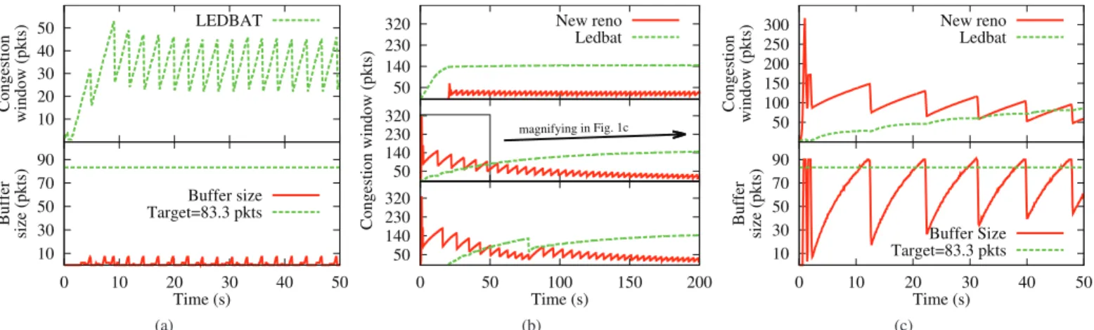
10 20 30 40 50 Congestion window (pkts) LEDBAT 10 30 50 70 90 0 10 20 30 40 50 Buffer size (pkts) Time (s) Buffer size Target=83.3 pkts (a) 50 140 230 320 New reno Ledbat 50 140 230 320 Congestion window (pkts) magnifying in Fig. 1c 50 140 230 320 0 50 100 150 200 Time (s) (b) 50 100 150 200 250 300 Congestion window (pkts) New reno Ledbat 10 30 50 70 90 0 10 20 30 40 50 Buffer size (pkts) Time (s) Buffer Size Target=83.3 pkts (c) Fig. 1: Time evolution of LEDBAT and TCP congestion windows and the queue length
notification), estimated by(Dack− Dmin). The target queuing
delay τ embodies the maximum queuing time that LEDBAT
is allowed to introduce.
The impact of delay variation, γ, is the reactivity of
LEDBAT to queuing delay variations. The bigger γ is, the
faster LEDBAT congestion control increases or decreases its congestion window. In order to prevent LEDBAT from being
too aggressive, the RFC states that γ must be lower than 1.
However in the RFC [1], in the LEDBAT implementation
in ns-2 [10] and in one study on the solutions to reduce
the aggressivity of LEDBAT [9], it has been implemented or discussed that the gain can be set to different values depending
on the sign ofD = τ − (Dack− Dmin): if D > 0, γ = γicr
(increase gain) and we define an upper bound forγicr× D (so
that LEDBAT does not increase its congestion window faster
than TCP); if< 0, γ = γdcr(decrease gain) which may not be
limited, to let LEDBAT raise the pace at which it decreases its congestion window when the queuing delay increases. To sum
up, increasingγdcr let LEDBAT be more sensitive to increases
of queuing delay and defining an upperbound for γicr× D
prevent LEDBAT from increasing its congestion window faster than TCP.
These considerations suggest that, in order to conclude on the possibility to integrate LEDBAT, it is primordial to assess
the reduction of LEDBAT aggressivity by increasingγdcr. Our
idea is thus to study the impact of buffer sizes, target value and decrease gain on the capability of LEDBAT to enable a Less-than-Best-Effort service.
III. LEDBATBEHAVIOR
In this section, we evaluate by simulation the impact of different buffer sizes on the behavior of LEDBAT in the presence of TCP New Reno (hereinafter simply denoted TCP).
A. Simulation setup
Simulations have been performed using the network
simu-latorns-2. We use the LEDBAT module developed by Valenti
et al. [10], based on the IETF RFC 6817 [1].
As reference network topology, we use a dumbbell topology where a TCP flow and a LEDBAT flow share a single bottleneck link. Both LEDBAT and TCP sources send packets
size ofP = 1500 B. The bottleneck link has a capacity set to
C = 10 Mb/s and a one-way propagation delay d = 50 ms. The bottleneck router uses a FIFO drop-tail queue with a
size ofB packets. For convenience, we express the bottleneck
buffer B as the ratio to the bandwidth-delay product BDP
in terms of packets. Hence, we have B = ⌈n ∗ BDP ⌉ =
⌈n∗C∗2∗d/(8∗P )⌉, where the ratio n ∈ [0.1, 0.2, . . . , 1.9, 2.0]
and ⌈x⌉ is the ceiling function. Since the value of B must
be an integer, we use the ceiling function to get the smallest
integer not less thanB. We explore the set of target queuing
delays τ ∈ [25, 50, 100] ms and the set of decrease gains
γdcr ∈ [1, 10]. We also express B as the ratio to the target
τ in the same way as with the BDP .
To analyze the behavior of LEDBAT with respect to dif-ferent buffer sizes, we consider the LEDBAT congestion window, the queue length of the bottleneck buffer, and the
link utilization η of LEDBAT and TCP flows.
We consider only long-lived TCP and LEDBAT flows.
Every simulation lasts 200 seconds, and the link utilization
is computed over the last 150 seconds of the simulation. We
denote by tX the time at which the flow using protocol X
starts to transmit data. The following scenarios are simulated:
• Scenario A: tLEDBAT = tT CP = 0 s;
• Scenario B:tLEDBAT = 0 s, tT CP = 20 s;
• Scenario C:tLEDBAT = 20 s, tT CP = 0 s.
B. Endangered TCP – LEDBAT misconfiguration
This section presents misconfiguration leading to a full utilization of the capacity by LEDBAT flows whatever the TCP load. Similar situations are also reported by other authors [4], [9]. In this work, we take a closer look at this problem and its relationship with the buffer sizing. Fig. 1 shows the time evolution of LEDBAT and TCP congestion windows as well as the queue length, in cases where LEDBAT does not fulfill its
primary objectives. The target isτ = 100 ms (≃ 83.3 packets),
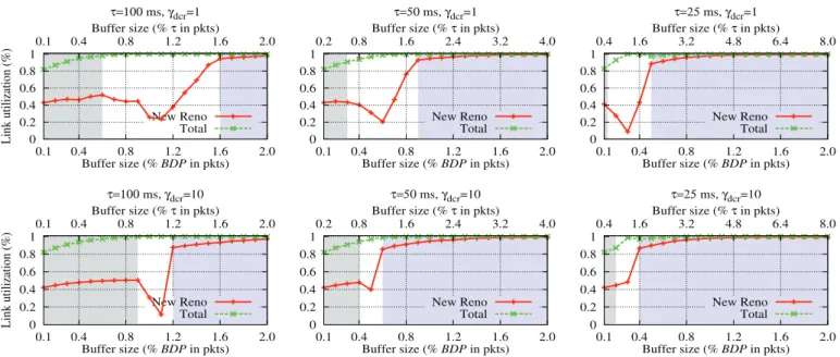
Link utilization (%) Buffer size (% BDP in pkts) τ=100 ms, γdcr=1 Buffer size (% τ in pkts) New Reno Total 0 0.2 0.4 0.6 0.8 1 0.1 0.4 0.8 1.2 1.6 2.0 0.1 0.4 0.8 1.2 1.6 2.0 Link utilization (%) Buffer size (% BDP in pkts) τ=100 ms, γdcr=10 Buffer size (% τ in pkts) New Reno Total 0 0.2 0.4 0.6 0.8 1 0.1 0.4 0.8 1.2 1.6 2.0 0.1 0.4 0.8 1.2 1.6 2.0 Buffer size (% BDP in pkts) τ=50 ms, γdcr=1 Buffer size (% τ in pkts) New Reno Total 0 0.2 0.4 0.6 0.8 1 0.1 0.4 0.8 1.2 1.6 2.0 0.2 0.8 1.6 2.4 3.2 4.0 Buffer size (% BDP in pkts) τ=50 ms, γdcr=10 Buffer size (% τ in pkts) New Reno Total 0 0.2 0.4 0.6 0.8 1 0.1 0.4 0.8 1.2 1.6 2.0 0.2 0.8 1.6 2.4 3.2 4.0 Buffer size (% BDP in pkts) τ=25 ms, γdcr=1 Buffer size (% τ in pkts) New Reno Total 0 0.2 0.4 0.6 0.8 1 0.1 0.4 0.8 1.2 1.6 2.0 0.4 1.6 3.2 4.8 6.4 8.0 Buffer size (% BDP in pkts) τ=25 ms, γdcr=10 Buffer size (% τ in pkts) New Reno Total 0 0.2 0.4 0.6 0.8 1 0.1 0.4 0.8 1.2 1.6 2.0 0.4 1.6 3.2 4.8 6.4 8.0
Fig. 2: Link utilization in terms of buffer size
RFC 6817 [1] states that, if a compromised target is set to infinity, “the algorithm is fundamentally limited in the worst case to be as aggressive as standard TCP”. Actually, it corresponds to the case where the buffer size is too small in comparison to the target, as shown in Fig. 1a. In this case,
the buffer size is9 packets, so the ratio of the buffer size to
the target is0.1. Thus, the queuing delay sensed by LEDBAT
never reaches the target. Therefore, LEDBAT always increases its sending rate until a loss event is reported.
However, there are circumstances “worse than RFC worst case” in which hostile LEDBAT makes TCP back off. Fig. 1b illustrates three hostile scenarios with a same network
con-figuration but with a buffer size of 92 packets. Even in an
unfavorable situation for LEDBAT, when it starts after TCP, LEDBAT succeeds to increase its congestion window more than TCP. Whatever the scenario presented in this section, TCP cannot compete against LEDBAT.
To understand this hostile behavior of LEDBAT, we inspect the scenario where two flows TCP and LEDBAT start at the same time (middle plot in Fig. 1b). In Fig. 1c, we magnify
the results of the first 50 seconds of the simulation. In the
slow-start phase, TCP increases exponentially its congestion window. As a consequence, the buffer fills up immediately and then blocks the LEDBAT congestion window to one packet.
After the slow-start phase, from t = 3 s to t = 5 s, as the
queuing delay is small compared to the target, LEDBAT and TCP congestion windows conjointly grow at the same speed. As the queue continues to increase, LEDBAT reduces the increasing speed of its congestion window. Meanwhile, TCP continues to increase linearly its congestion window. After t = 11 s, when the queuing delay is higher than the target, LEDBAT decreases slowly and slightly its congestion window. Although the buffer size is bigger, it remains relatively small
to the target. The ratio of the target to the buffer size is1.1
in this case. Thus, LEDBAT does not have enough time to react to queuing delay before TCP causes a buffer overflow
at t = 15 s. After that, TCP halves its congestion window,
resulting in a reduction of the queuing delay. Since the queuing delay is now below the target, LEDBAT raises again its congestion window conjointly with TCP. Consequently, after several cycles, LEDBAT exploits more capacity than TCP.
C. LEDBAT working regions
The previous section illustrates cases where LEDBAT is too aggressive. In this section, we identify different working regions of LEDBAT. We denote as “working regions” areas where LEDBAT behaves correctly as a LBE protocol. For each couple of target and decrease gain, we plot the link utilization of TCP flow and the total link utilization of two flows against the buffer size.
Fig. 2 presents only the simulation results from the scenario where two TCP and LEDBAT flows start at the same time (i.e., Scenario A). We do not present the results of Scenario B and C as similar behavior is observed. Each plot corresponds to a couple of target and decrease gain. From left to right, the
target slides from100 ms to 25 ms. The decrease gain is set to
1 in the first row and 10 in the second row. The first (bottom)
x-axis is the ratio of the buffer size to theBDP . The second
(top) x-axis represents the same buffer size but as the ratio to the target. The y-axis is the link utilization.
1) Impact of the target: Fixing the decrease gain to 1, we study the impact of the target setting on the behavior of LEDBAT. As shown in Fig. 2, we distinguish three operating regions of LEDBAT. First, in the leftmost region, LEDBAT behaves like TCP. In other words, as previously explained in Section III-B, LEDBAT always increases its sending rate until a loss event is reported. In this case, the buffer size is small in comparison to the target. Hence, TCP and LEDBAT
middle region, LEDBAT starts to become hostile to TCP. In consequence, the link utilization of TCP reduces progressively
to a certain point (ηTCP ≪ ηLEDBAT). As the buffer size still
increases, the aggressiveness of LEDBAT decreases. Finally, in the rightmost region, LEDBAT works correctly as a LBE
protocol (ηTCP ≫ ηLEDBAT). To have enough time to react to
queuing delay variations, we measure that LEDBAT needs a
large buffer size in comparison to its target (more than 1.5
times).
Considering now the buffer size in terms of the ratio to the BDP , we see that a target of 100 ms requires a buffer size
as large as 1.6 times the BDP in order to perform in
low-priority mode. This excess need of buffer introduces an ex-cessive queuing delay known as bufferbloat phenomenon [7]. A smaller target mitigates this issue. As seen in Fig. 2, the smaller is the target, the smaller is the size of the buffer.
2) Impact of the decrease gain: We now study the impact of the decrease gain setting on LEDBAT behavior. Fig. 2 shows that, for each target, increasing the decrease gain shrinks the hostile region from both sides. As a consequence, the LBE region expands to the left, meaning a reduction in the need for buffer size of LEDBAT for low-priority mode. However, a higher decrease gain also amplifies the loss-based region.
As a conclusion, to increase the LBE working region of LEDBAT, we can reduce the target or raise the decrease gain separately or in the same time. We also highlight that setting LEDBAT parameters is a trade-off as a target too small could make LEDBAT sensible to network conditions and a decrease gain too high could reduce significantly its performance.
IV. OPTIMAL COUPLE OF TARGET AND DECREASE GAIN In this section, we assess if there exists a couple of target and decrease gain allowing LEDBAT to behave as LBE protocol whatever the network configuration is.
A. Network configuration
We use the same dumbbell topology as in
Section III. We consider different capacities
C ∈ [1, 5, 10, 20, 50] Mb/s and different one-way propagation
delays d ∈ [10, 50, 100, 150, 200, 250] ms of the bottleneck
link. As in Section III, we express the bottleneck buffer B
as the ratio to the bandwidth-delay product BDP . For each
network setting C, d, and B, we explore the set of target
queuing delays τ ∈ [5, 25, 50, 75, 100] ms and the set of
decrease gains γdcr ∈ [1, 10]. Therefore, we run about 60
simulations for each setting of target and decrease gain. We
drove only fewer simulations for smallBDP networks as we
exclude all cases with duplicate values of B caused by the
ceiling function and whereB is equal to 1.
In each simulation, a LEDBAT flow starts att = 0 s and
then a TCP flow starts att = 200 s later. The simulation lasts
1000 seconds. We calculate the link utilization η of each flow
over the last500 seconds.
We use the following clustering method to classify our data and represent the set of working couples. The classification method is defined as follows: for each couple of target and
0 20 40 60 80 100 120 5 25 50 75 100 5 25 50 75 100 5 25 50 75 100 5 25 50 75 100 5 25 50 75 100 Number of R and W R W 1 (Mb/s) 5 (Mb/s) 10 (Mb/s) 20 (Mb/s) C=50 (Mb/s)
Fig. 3: Number ofR and W cases for each target setting
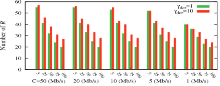
0 10 20 30 40 50 60 5 25 50 75 100 5 25 50 75 100 5 25 50 75 100 5 25 50 75 100 5 25 50 75 100 Number of R γdcr=1 γdcr=10 1 (Mb/s) 5 (Mb/s) 10 (Mb/s) 20 (Mb/s) C=50 (Mb/s)
Fig. 4: Number ofR cases when γdcr= 1 and γdcr= 10 for
each target setting
decrease gain, whenB = BDP , if the link utilization of TCP
flow ηTCP is greater than or equal to 0.8, then we choose the
link utilization of LEDBAT flow as reference ηref= ηLEDBAT.
Then, for every other value of B, we calculate∆ = |ηLEDBAT−
ηref|. If ∆ is less than or equal to a certain value of ε and
ηTCP≥ 0.8, then we classify B in the cluster “Right” (denoted
R), otherwise, in the cluster “Wrong” (denoted W ). In our study, we useε = 0.15. So, for different buffer sizes, if ηTCPis
always greater than or equal to 0.8 and the difference between
ηLEDBAT and ηref is in a limit of 15%, then we say that the
couple of target and decrease gain works well for these buffer sizes.
Finally, we use statistical analysis to find which couple of target and decrease gain works well in most network configurations.
B. Choosing the target
We begin our analysis by finding the optimal target value. In Fig. 3, using histogram, we group the simulation results into different categories of network capacities and then, into subclass of target values. For every target value, the stacked
column represents the number of R and W cases. The
col-umn height corresponds to the total simulations including all decrease gain setting for a target value. For each setting of target, we have 120 simulations for high capacity networks and fewer simulations in case of small capacity networks.
In Fig. 3, we observe that the number of R cases of a
target decreases as the network capacity decreases. Actually,
the buffer size, expressed in ratio to the BDP , reduces when
the network capacity is smaller. Therefore, the ratio of the buffer size to the target also becomes smaller. In consequence, LEDBAT behavior falls back into either hostile region or loss-based region.
As expected, Fig. 3 shows that a target value of5 ms works in most cases. These experiments allow us to conclude that setting the target to5 ms is optimal.
C. Choosing the decrease gain and the optimal couple of LEDBAT parameters
Having the optimal target value, we still use the histogram representation to find the optimal decrease gain. For each
target setting, we present the number of R cases for each
corresponding decrease gain value. As shown in Fig. 4, setting
the decrease gain to10 is better as it increases the number of
R cases.
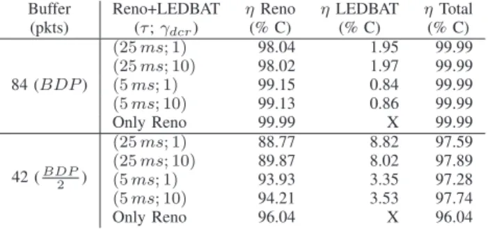
D. Testing the optimal couple
We now evaluate the optimal couple of target and decrease gain using the network configuration in Section III. Moreover, for reference purpose, we also simulate the scenario where TCP is the only protocol in the network. Table I reports
results of two cases where B = BDP = 84 packets and
B = BDP
2 = 42 packets. For comparison, we are only
inter-ested in couples of parameters that work in low-priority mode
with either buffer sizes, i.e.,(25 ms; 1) and (25 ms; 10) (see
Fig. 2 in Section III). Beside, we report also the performance
of the runner-up couple(5 ms; 1).
TABLE I: Optimal LEDBAT sharing bandwidth with Reno
Buffer Reno+LEDBAT ηReno ηLEDBAT ηTotal
(pkts) (τ ; γdcr) (% C) (% C) (% C) 84 (BDP ) (25 ms; 1) 98.04 1.95 99.99 (25 ms; 10) 98.02 1.97 99.99 (5 ms; 1) 99.15 0.84 99.99 (5 ms; 10) 99.13 0.86 99.99 Only Reno 99.99 X 99.99 42 (BDP2 ) (25 ms; 1) 88.77 8.82 97.59 (25 ms; 10) 89.87 8.02 97.89 (5 ms; 1) 93.93 3.35 97.28 (5 ms; 10) 94.21 3.53 97.74 Only Reno 96.04 X 96.04
When the buffer size equals toBDP , TCP alone exploits
almost full capacity of the network (99.99%). Introducing LEDBAT using the optimal couple of parameters reduces TCP performance by 0.86% while keeping the total throughput same as in the case of TCP alone. In this case, the performance
of the runner-up couple (5 ms; 1) is a little better than the
optimal couple and could be neglected.
When the buffer size equals to BDP2 , TCP alone obtains
less network capacity (96.04%). But in this case, introducing LEDBAT using the optimal couple of parameters increases the
total network capacity exploited by1.7% while causing least
impact on TCP performance. The couple(25 ms; 10) allows to
obtain a better network capacity, but also makes more impact on TCP in the same time.
Finally, we conclude that the optimal couple of target and
decrease gain is(5 ms; 10). This result is consistent with our
discussion in Section III.
V. LEDBATIN HIGHLY LOADED NETWORKS
In this section, we test the optimal couple of target and gain of LEDBAT found in Section IV in a highly loaded network. We also take this opportunity to evaluate other LBE protocols like TCP Nice [11] and TCP-LP [12]. TCP-LP implementation
is available in ns-2 TCP-Linux. For TCP Nice, we use the
module proposed in [4].
As in Section III, we use a dumbbell topology with a
bottleneck capacityC = 10 Mb/s and a one-way propagation
delay d = 50 ms. The buffer size is set to 84 packets and
equals to theBDP , according to the classical “rule-of-thumb”.
In each simulation, we considerN LBE sources and N TCP
sources, where N ∈ [1, 10, 20, 40, 60, 80, 100]. The starting
time of a TCP flow is uniformly distributed between 0 and 200 seconds. To assess on the impact of LBE protocols on TCP, LBE flows begin to transfer data in an unfavorable situation, i.e., only after all TCP flows have started. Therefore, the starting time of a LBE flow is uniformly distributed between 300 and 500 seconds. It should be noticed that the late-comers problem of LEDBAT is negligible when there is interaction between LEDBAT and TCP [10]. Thus, in our study, we introduce LEDBAT at random time neglecting any effects on
our results. We also simulate onlyN TCP flows without other
competing LBE flows as reference.
As performance metrics, apart from the aggregate aver-age throughput, we also define the TCP bandwidth released
(T CPreleased) as the link utilization of TCP when it shares
the bottleneck link with the tested LBE protocol over the link utilization of TCP when it is the only protocol on the same link, i.e., T CPreleased= ηT CPReno+LEDBAT/ηT CPonly Reno.
Every simulation lasts 1200 seconds, and all metrics are measured over the last 600 seconds.
A. Results and discussions
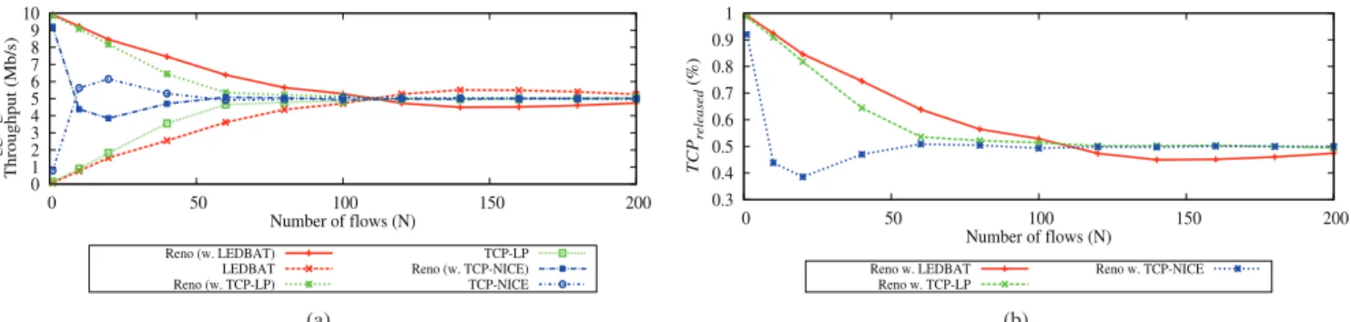
Fig. 5a presents the aggregate average throughput of N
TCP flows and N LBE flows sharing the bottleneck link. To
weight up the impact of LBE flows, we plot in Fig. 5b the
T CPreleased depending on the network load, i.e., the direct
impact of the introduction of LBE flows on TCP performance. As seen in Fig. 5, when the number of TCP and LBE flows is small, LBE protocols fulfill their role. However, increasing the number of LBE flows also increases their impact on TCP traffic, even though an equivalent amount of TCP flows is also introduced into the network. The more we introduce LBE flows, the less capacity is left for TCP traffic. For instance, 100 LEDBAT flows compete as aggressive as 100 TCP flows for the full capacity. In this case, TCP flows must yield to
LEDBAT flows 47 % of the bandwidth obtained when they
are alone in the network.
When the number of flows is above 100 (Fig. 5a), LEDBAT is even more aggressive. This is explained by the misesti-mation of the OWD. Indeed, LEDBAT keeps track of the
minimum One-Way Delay Dmin in order to estimate the
queuing delay variation. Thus, if LEDBAT runs long enough
and the queue is never empty, Dmin is always nearly equal
0 1 2 3 4 5 6 7 8 9 10 0 50 100 150 200
Aggregate Mean Throughput (Mb/s)
Number of flows (N) Reno (w. LEDBAT) LEDBAT Reno (w. TCP-LP) TCP-LP Reno (w. TCP-NICE) TCP-NICE (a) 0.3 0.4 0.5 0.6 0.7 0.8 0.9 1 0 50 100 150 200 TCP released (%) Number of flows (N) Reno w. LEDBAT Reno w. TCP-LP Reno w. TCP-NICE (b)
Fig. 5: Impact ofN LBE flows on N TCP flows
bottleneck buffer. As a result, the queuing delay sensed by
LEDBAT always approximates to zero (Dack− Dmin ≃ 0).
In consequence, LEDBAT tends to raise its congestion window to reach the target queuing delay. This limitation of LEDBAT algorithm is studied in detail in [6]. As shown in Fig. 5, if we do not limit the number of LBE flows, an aggregate of LBE flows do not behave as a LBE traffic anymore.
To better understand this problem, we measure the average congestion window of a LEDBAT flow, in the case where the number of flows of each protocol TCP and LEDBAT is 100. As a result, the average congestion window of a LEDBAT flow is 1.3 packet. Thus, a LEDBAT flow sends data at an average rate of 1.3 packet per RTT. For 100 LEDBAT flows, the router always receives on average a burst of 130 packets. An exponential backoff mechanism, as proposed in RFC 6817 [1], could help to reduce the burst size at a given time. Note that this mechanism is already implemented in the LEDBAT module used in our simulations. Unfortunately, exponential backoff does not resolve this issue on the long term as we must impose a maximum backoff time. Although the RFC 6817 states that a maximum value MAY be placed on backoff time, we argue that this maximum value MUST be always set. If LEDBAT flows can backoff in unlimited time, their impact on long-lived TCP traffic will then reduce significantly. This could lead to case where long-lived TCP flows cut off LEDBAT traffic in long periods of time. Moreover, unlimited backoff time could raise a potential intra-unfairness of LEDBAT flows as a side effect.
Our results in this section indicate that when LEDBAT is deployed at large scales, we must use additional strategies to limit the number of LEDBAT flows.
VI. CONCLUSION
Recent studies pointed out cases in which the capacity of LEDBAT to carry out Less-than-Best-Effort is questioned. The misconfiguration of this protocol may result in a significant delay in the network. This motivated us to lead a deep analysis on the impact of its internal parameters on its performance.
We propose an optimal parametrization for the internal parameters of LEDBAT. We found that a target of 5 ms and a decrease gain of 10 are optimal. The optimal target is far from
the guideline in the RFC, which says that the target must be lower than 100 ms. However, it is worth pointing out that in all simulation cases, LEDBAT is not fully LBE and borrows some capacity of the primary flows. We also measure the impact of the increasing number of LEDBAT flows which is alarming.
We conclude that the congestion control of LEDBAT must be adapted before large scale implementation.
ACKNOWLEDGMENTS
This research work has been supported by funding from CNES and Thales Alenia Space. Nicolas Kuhn is supported by the RITE project. The authors wish to thank Arjuna Sathiaseelan for numerous discussions.
REFERENCES
[1] S. Shalunov, G. Hazel, J. Iyengar, and M. Kuehlewind, “Low Extra Delay Background Transport (LEDBAT),” RFC 6817, 2012.
[2] D. Rossi, C. Testa, and S. Valenti, “Yes, We LEDBAT: Playing with the New BitTorrent Congestion Control Algorithm,” in Passive and
Active Measurement, ser. Lecture Notes in Computer Science, A.
Kr-ishnamurthy and B. Plattner, Eds. Springer Berlin Heidelberg, 2010.
[3] A. Sathiaseelan and J. Crowcroft, “The free Internet: a distant mirage or near reality?” University of Cambridge, Tech. Rep., 2012. [4] G. Carofiglio, L. Muscariello, D. Rossi, and C. Testa, “A hands-on
assessment of transport protocols with lower than best effort priority,” in Proceedings of the 2010 IEEE 35th Conference on Local Computer
Networks, ser. LCN ’10. IEEE Computer Society, 2010.
[5] N. Kuhn, O. Mehani, A. Sathiaseelan, and E. Lochin, “Less-than-Best-Effort Capacity Sharing over High BDP Networks with LEDBAT,” in
VTC 2013-Fall, 78th Vehicular Technology Conference, O. Altintas, F. Dressler, and A. Wyglinski, Eds., IEEE Vehicular Technology Society. Los Alamitos, CA, USA: IEEE Computer Society, 2013.
[6] D. Ros and M. Welzl, “Assessing ledbat’s delay impact,”
Communica-tions Letters, IEEE, vol. 17, no. 5, pp. 1044–1047, 2013. [7] “BufferBloat: What’s Wrong with the Internet?” Queue, 2011. [8] D. Genin and J. Splett, “Where in the Internet is congestion?” ArXiv
e-prints, Jul. 2013.
[9] M. K¨uhlewind and S. Fisches, “Evaluation of different decrease schemes for LEDBAT congestion control,” in Proceedings of the 17th
interna-tional conference on Energy-aware communications, ser. EUNICE’11. Berlin, Heidelberg: Springer-Verlag, 2011, pp. 112–123.
[10] D. Rossi, C. Testa, S. Valenti, and L. Muscariello, “LEDBAT: The New BitTorrent Congestion Control Protocol,” in Computer Communications
and Networks (ICCCN), 2010 Proceedings of 19th International Con-ference on, 2010, pp. 1–6.
[11] A. Venkataramani, R. Kokku, and M. Dahlin, “TCP Nice: a mechanism for background transfers,” SIGOPS Oper. Syst. Rev., vol. 36, no. SI, pp. 329–343, 2002.
[12] A. Kuzmanovic and E. W. Knightly, “TCP-LP: low-priority service via end-point congestion control,” IEEE/ACM Trans. Netw., vol. 14, no. 4, pp. 739–752, 2006.