Publisher’s version / Version de l'éditeur:
Technical Translation (National Research Council of Canada), 1964
READ THESE TERMS AND CONDITIONS CAREFULLY BEFORE USING THIS WEBSITE. https://nrc-publications.canada.ca/eng/copyright
Vous avez des questions? Nous pouvons vous aider. Pour communiquer directement avec un auteur, consultez la
première page de la revue dans laquelle son article a été publié afin de trouver ses coordonnées. Si vous n’arrivez pas à les repérer, communiquez avec nous à [email protected].
Questions? Contact the NRC Publications Archive team at
[email protected]. If you wish to email the authors directly, please see the first page of the publication for their contact information.
NRC Publications Archive
Archives des publications du CNRC
For the publisher’s version, please access the DOI link below./ Pour consulter la version de l’éditeur, utilisez le lien DOI ci-dessous.
https://doi.org/10.4224/20375694
Access and use of this website and the material on it are subject to the Terms and Conditions set forth at
Fire Tests on Glued Laminated Structural Timbers (Glulam Beams)
Dorn, H.; Egner, K.; National Research Council of Canada. Division of
Building Research
https://publications-cnrc.canada.ca/fra/droits
L’accès à ce site Web et l’utilisation de son contenu sont assujettis aux conditions présentées dans le site
LISEZ CES CONDITIONS ATTENTIVEMENT AVANT D’UTILISER CE SITE WEB.
NRC Publications Record / Notice d'Archives des publications de CNRC: https://nrc-publications.canada.ca/eng/view/object/?id=8e55f065-18a5-486f-9516-b17eba1c2161 https://publications-cnrc.canada.ca/fra/voir/objet/?id=8e55f065-18a5-486f-9516-b17eba1c2161
FIRE TESTS ON GLUED LAMINATED STRUCTURAL TIMBERS
(GLULAM BEAMS)
it:?t
4 NRC I TT.1131 NRC TT -1131NATIONAL RESEARCH COUNCIL OF CANADA
TECHNICAL TRANSLATION 1131
BY
H. DORN AND K. EGNER
FROM
HOLZ . ZENTRALBLATT STUTTGART, (28): 435·438, 1961
TRANSLATED BY
D. A. SINCLAIR
THIS IS THE ONE HUNDRED AND TWENTIETH OF THE SERIES OF TRANSLATIONS
PREPARED FOR THE DIVISION OF BUILDING RESEARCH
OTTAWA
1964
PREFACE
The Division of Building Research of the National Research Council works in close cooperation with the Forest Products Research Branch of the Federal Department of Forestry in all building research matters involving the use of wood. \lith the knowledge and agreement of FPRB the Division is now pleased to publish this significant translation of a paper from German technical literature on a subject on which there is very little written information.
The losses claimed each year by fires in buildings are staggering. Although fires will never be prevented completely, it is obvioUB that a better understanding of fire behaviour must form the basis for im-proved methods of the control of fire as well as for the formulation of improved requirements for fire resistance in building codes.
The Division of Building Research through its Fire Research Section is devoting a considerable portion of its time and budget to studies in a broad field of fire research. Among others large-scale fire tests are being carried out by means of special furnaces to determine the fire resistance of building elements such as floors, walls, beams and columns. In this work the Division is keeping in close touch with other organizations active in this field in Canada, the U.S.A. and overseas.
Through technical translations of papers in the subject an effort is made to facilitate the exchange of knowledge. The Division of Building Research is therefore glad to make available this translation of a paper on German tests on full-scale glued laminated timber beams which were made to provide information on the behaviour of such beams under severe fire conditions. To this end a number of beams of
different cross-section were fabricated with different glues and exposed to fire with temperature increases according to the standard German DIN Specification 4102.
It will be noted that the beams employed in the tests performed well. In particular the behaviour of the adhesives was very
prom-ising. The flexural strengths of the beams were determined before and after the exposure to fire to obtain information on the strength and SUitability of the glues when SUbjected to heat. The authors are members of the State Research and Materials Testing Institute for the Construction Industry of the Technical University of Stuttgart, Otto Graff Institute.
The Division wishes to express its appreciation to Mr. D.A. Sinclair of the Translations Section for translating the paper. Ottawa
June, 1964
H.F. Legget Director
NATIONAL RESEARCH COUNCIL OF CANADA Technical Translation 1131
Title: Fire tests on glued laminated structural timbers (glulam beams)
(Brandversuche mit geleimten Holzbauteilen (Hetzer-Balken»
Authors: H. Dorn and K. Egner
Reference: Holz-Zentralblatt Stuttgart,
(28): 435-438,
1961
-4-Tests and Measurements Bending tests before the fire tests
A few of the specimens were subjected before the fire tests to bending loads, by means of the arrangement shown in Fig. 1, with a view to determining their elastic behaviour as ウセョーャケ supported beams on two supports.
The moduli of elasticity were determined from the elastic deflections. Loading was increased only up to a maximum bending stress of approximately 100 kg/cm2
, i.e. the stresses in these tests were kept to the permissible values according to DIN 1052 for wooden structural parts of quality class II DIN 4074.
Fire tests
The increase of temperature in the fire tests was controlled according to the standard temperature curve of DIN 4102, Sheet 3 (Fig. 2). For this purpose a gas-heated test installation (furnace) according to Fig. 3 was employed with the following arrangement and mode of operation.
Each specimen was laid on fireproof clay bricks which supported them with a span 1
=
410 cm in the centre of the furnace space (length of each bearing surface approximately 25 cm). The furnace was closed with a removable cover, 80 that the fire space was enclosed on all sides during the test.Eleven gas burners arranged in staggered fashion horizontally along the two longitudinal walls served for heating and controlling the temperature of the furnace. With the aid of so-called deflection plates (see Fig.
3,
cross-section A-B) the gas flames were conducted underneath the beam and in the fire space on the side opposite the burner upwards between the furnace wall and the specimen to just below the top edge of the beam. An additional air distribution duct below the combustion chamber floor with numerous holes into the furnace space made it possible to maintain a supply of supplementary fresh air (secondary air). With the aid of several thermocouples ofNiCr-Ni-wire (1 mm diameter) inserted in the longitudinal walls (hot ends open, about 10 cm from the specimen), the temperatures in the fire space were determined with continuous recording of the thermal stresses through a
12-point compensation recording instrument. In order to control the tests the mean temperature values were obtained from at least four measuring points (two in the upper and two in the lower part of the furnace).
Before the fire test the test installation was preheated in such a way that after introduction of the specimen into the warm furnace (With the gas heaters turned off), the temperature in the interior was at approximately 100°C. After closing the cover and igniting the burners the fire test was controlled in accordance with the standard temperature curve.
-5-In the great majority of cases a secondary supply of air (generally from the 5th minute after the beginning of the test) was provided. This ensured practically complete combustion of the gases emanating from the specimen as the fire proceeded.
After 30 minutes firing (in two cases 60 minutes) the gas and air supply were turned off, the specimen, which was suspended from the cover, was immedi-ately removed from the apparatus and immersed in a closable container. By the introduction of nitrogen (in two cases by filling the container with water), the burning of the specimens was in each case entirely stopped within a few minutes. Directly afterwards the charcoal was removed with the aid of rasps down to the still firm wood material. Since the Burface of the
undisturbed wood of the specimen was no longer entirely flat, a thin layer of darkened or charred wood remained in most cases on the surfaces after they had been worked in this way.
Temperature measurements in the interior of the specimen
In order to follow the course of the temperature inside the wood during and after the fire tests some of the specimens had thermocouples embedded in the wood. For this purpose, holes about 4 mm in diameter were bored into the wood from one side of the beam across the entire cross-section for the intro-duction of NiCr-Ni thermocouples. The hot ends (consisting of weld beads 2 mm thick and about 4 to 5 mm long) of the taut wires, were kept in position by wedging them against the wood, after which the remaining spaces were
stuffed with asbestos rope. The distribution of the thermocouples over the beam cross-section with respect to both vleiV1t and width of the beam is seen in Fig. 4. The resulting temperature measurements were also made with the above-mentioned compensation recording instrument.
During the tests the thermocouple wires were subject to temperature effects due to heating of the test leads which were led unprotected through the furnac6 space. These influences showed up in some cases as discontinu-ities in the temperature curves. After the conclusion of each fire test, i.e. with the cooling of the specimen, in most cases a rapid drop in the temperature values of these measuring points occurred.
From this point on, the recorded temperatures can be regarded as suffi-ciently accurate without correction, as the smooth curves indicate. In order to eliminate the temperature effects during the fire mentioned earlier, the curves were partially corrected, taking into account the discontinuity in the recorded values occurring immediately at the end of the test, since it can be assumed that no such rapidly alternating temperature changes occurred in the wood itself.
-6-Bending tests after the fire tests
Directly after the fire test another bending test of the specimen was carried out (except in the case of those specimens in which the temperature was followed for a loneer time); the time between the termination of the fire test and the beginning of the bending test was usually 1.5 to 2 hours. As will be seen below, the beams were usually still warm (at least in their interior) when this bending test took place.
The loading arraneement was the same as that described in the first paragraphs of this section. The loads applied to determine the deflections were also the same. The loads were then increased up to the breaking load of the specimen.
Additional measurements on the test specimens
After the fire test and removal of the charcoal layers (cf. above) the widths of the cross-sections were measured in the vicinity of the top and bottom edges and the heights of the cross-sections in
3
to5
places uniformly distributed along the length (the extreme points of measurements in each case were about 20 em from the ends of the beams). From the measurements (mean values) before and after the fire test, the mean depth of consumption (depth of consumption tb or th ; half the difference between the width or height of cross-section before the beginning of the test and after removal of the charcoal layers following the test) was determined. After removal of the charcoal the specimens were also weighed in order to determine the 1088 of
weight (consumed weight).
Before the fire test the moisture content of the wood was measured by means of an electrical moisture meter with the aid of measuring electrodes. To determine the distribution of the moisture over the cross-section after the fire test slices 1 em thick were removed at various distances from the ends of the beam and were divided into strips about 1 cm wide. The moisture contents of these strips were determined according to the Darr method,
DIN 52,183.
Test Results Fire tests
Because the temperature increases were initiated in the test apparatus (furnace) primarily from below or from the side, somewhat higher temperatures prevailed in the lower parts of the furnace than in the upper zones. The differences relative to the mean values on the average were apprOXimately セX to 10% (a maximum of up to about 20% in individual cases). The mean values
-7-(from 4 or 5 measuring points) generally conformed satisfactorily to the standard temperature curve. Some of the temperature curves recorded (mean value curves) are shown in Fig.
5.
For specimens A 2 and WIthe tests were conducted without furnishing any secondary air. Apart from a higher fuel consumption during the starting period, no appreciable departures from the course of the fire and the con-sumption effect were found compared with the tests in which secondary air was supplied.
A gradual burning of the wooden specimens on their own started during the first 5 minutes of the test. Little by little the furnace became filled with flames, accompanied by progressive charring of the test specimen.
When the specimen was removed from the furnace after the gas burner had been turned off, the flames rapidly receded on the surfaces and died down almost totally in the air Hithin a few minutes. 'fhe test specimens were completely charred on all sides and showed the characteristic longitudinal and lateral shrinkage cracks in the charcoal layers. The longitudinal joints
(glued joints) between the laminae were clearly visible. In none of the specimens, apparently, did the bond (adhesion) between the boards disappear; only in isolated cases did the charred remnants of the top or bottom boards of the specimen become partially separated. At the two points of support of the beam (on the fireproof clay bricks in the furnace) the consumption was definitely less in all cases than on the exposed surfaces.
Figures
6
to 14 show pairs of croGs-sections of the same (or similar) specimens before and after the fire tests. The pictures of the undamaged cross-sections were in each case taken from the ends of the beams, while those after the fire tests are from sections taken at various distances from the ends of the beams. This explains why the pattern of annual rings in the pictures of the same beam taken before and after the fire test sometimes show slight differences.The weight consumption values (weieht losses) obtained in the tests and the values of the depth of consumption (burnt depth) calculated from the thickness and height measurements of the individual test specimens are given in Table II.
According to these figures the specific cons umed wetght; (Height loss per unit of original beam surface) was about 6.5 lq?/m2
after 30 minutes; the group mean values for the five different test specimen sizes varied between
6.4
and6.7
kg/m2 • After an hour's exposure to the fire the specimens with16
em x 40 em cross-section sho\led a specific consumed weight of about 15.5 kgjm2, i.e. aomewhat more than twice the )0 minute value...
The mean consumed depth '0"o (measured horizontally) was about 1.7 em, with a scatter of group mean values bet"leen 1.65 and 1.70 em, after 30 minutes. After 60 minutes the value was about 4 em. The loss of height in the
majority of cases was somedhat greater: the mean consumed depth (measured vertically) was between about 1.65 and 1.90 em after 30 minutes exposure and about 6.25 em after 60 minutes. This circumstance is partly due to the some-what greater exposure to the fire in the 10vIer part of the furnace space and also to the fact that in scraping off the charcoal ('.'lith a rasp) in many cases the top and bottom laminae became separated from the rest at the same time. This was specially the case for specimen HH 7.
Specimen A 3 shO\'led surprisinGly low values both for the consumed weight and the 」ッョウエセ・、 depth; based on temperature curves this could be attributed to the fire exposure having been a little too low. Otherwise, however, the variations in the different measured values remained vii thin comparatively narrow limits.
Results of bending tests before and after the fire test
The breaking loads P of the specimens with 16 x 40 em original cross-max
sections lay between 12.'7 and about 20.l.j· metric tons (Table II, column 11). Dividing these specimens into three Groups according to the kind of glue employed, the followinG mean values of the ratio Pmax : Pa11 are obtained
0\'/.
for the 30 minutes exposure: (p 11 is the load at which, based on the size
a ovr ,
of the original cross-section, a span 1
=
4.1 m and uniformly distributed load, a maximum bending stress of 100 kg/cm2 is calculated.)Specimen constructed with Kauresin 440 Kaurit '.1 Kaurit ',iRK P max p a LLow . 2.31 2.17 1.67
Forming the averaGe for all eight tested specimens With a cross-section 16 x 40 em (Without regard to the kind of glue) we find that the breaking loads after 30 minutes supported on the average 2.05 times the permissible loads (design loads).
In specimens of equal cross-section exposed to the fire for one hour a breaking load on the average was only about half the permissible load (design load) .
Specimens K 121 and K 122, with original cross-sections of 12 x 40 cml carried a load of approximately 1.2'7 times the desiGn load after a fire test of 30 minutes; specimens K 81 and K 82, with initial cross-sections 8 x 40 em,
..
-9-on the still supported 0.99 times the design load. This significant reduction of the breaking load with decreasing width of cross-section must be attributed to the comparatively large (especially in the latter case) losses of cross-section due to charring.
The specimens with the 12 x 30 em cross-section gave on the average about 2.1 times the design load, although the two individual values varied consider-ably. For the specimens with still smaller cross-sections of
8
x 20 emreliable values of the breaking load could not be determined at all, since no testing machine with a suitable load range for this purpose was available at
the time.
Table III shows the results of the deflection measurements on some of the specimens during the bending tests.
The values of the modulus of elasticity calculated from the elastic deflections before the fire test averaged around 99,000 kg/cm2 for specimens
vlli 6, WH 8 and WH 9, around 100,000 kg/cm2 for specimen K 122 (height of beam
in both cases 40 cm), 122,000 kg/cm2 for K 123 (beam height
30
em) and 124,000 kg/cm2for K
85
(beam height 20 em), i.e. somewhat higher values in the latter two cases.Before exposure to the fire the deformations in the bending test lay in all cases within the elastic range, but after the fire test permanent deflec-tions averaging up to a maximum of 1.0 mm, i.e. up to about
5%
of the total deflection were found in the specimens with moduli of approximately100,000 kg/cm2
, and up to about 2 to 3% in the specimens \'lith the higher
modulus of elasticity values. It is important to state, however, that during the loading test after the fire, OWing to the reduction of the cross-section due to consumption of the wood, considerably higher stresses occurred in the specimens for loads of equal value, and hence permanent deformations resulted due to excessive stressing.
The ratios of the elastic deflections before the fire test to those
occurring after the test (f : f e) are about
1.89
and2.59
for the specimens28 1
of 40 em cross-sectional heightj for the two specimens with 30 and 20 em cross-sectional height this ratio was about 2.7 to
2.8
(Column8,
Table III). Temperature changes in the wood during and after the fire testFigures 15, 16 and 17 show the changes of the temperatures measured in the interior of the セャッッ、 for a number of test specimens with cross-sections 16 x 40 em, as a function of the time. Figure
18
shows the temperatures after 30 minutes fire testing as a function of the distance from the surface(wood depth). These curves show the rapid rise of the temperatures in the outer (charring) zones, while in the interior of the specimen, depending on
-
-10-the position of -10-the measuring points, -10-the increase in much slower. After 30 minutes of fire testing only about 5 to 10°C increase of temperature was measured at depths of about
7
cm and up (measured from the original surface of the \'lood). The temperature of approximately 200°C, which can be regarded as a critical one for destruction of the texture, was reached at this time at a depth of about2.5
em (cf. Fig. 18).The steep drop of the temperature curve from the charring zone to the interior of the wood (Fig. 13) illustrates the very favourable conditions from the point of View of fire resistance that exist in the interior of the wood due to its poor heat conductivity.
After the fire was stopped a further temperature increase was measured at all measuring points inside the unburned wood. The rise in temperature due to heat conduction from the outside to the inside zones lasted up to
1.5
hours after the エ・ャセゥョ。エゥッョ of the fire for the case of the innermost points. The temperature at measurin0 point 3 in the interior of the wood(about 7 em above the original bottom edge) in specimen \JH 6, was still 60°C above the temperature of the surrounding air (13°C) an hour after the fire
(cf. Fig.
15).
At this time, the temperature had risen by about52°C
(to about65°C)
in the innermost zone. The temperature increases were slightly lower in specimen WH 9 under the same fire test conditions, but with the measuring points arranged along the horizontal centre plane (lateral direction; cf. Fig. 17).After being stored about 18 hours at 10°C air temperature the specimens still showed higher temperatures in their interior zones than at the beginning of the fire tests.
Distribution of moisture over the bcnm cross-section after the fire test Figure 19 shows the distribution of the moisture along the horizontal axis (lateral direction) for two hnlf sections of specimens with
16
cm original width. The left-hand side of the diagram refers to a fire test of30
minutes and the right-hand half to one of 60 minutes. As expected, the outer zones (With residues of ch::lrrccl Hood) are almost completely dried out. In the zones closer to the interior of tlle speclmen the moisture content had increased owing to misrntion of moisture from outside to inside, to about 15 to16;:,
owing to the movement of hcat in the aame direction, whf.Le in the innermost zones only about ャ[[セGZ moisture content vas present, corresponding to the nverage for the HOOti before the fire tests.From the curves of ュPQセエオイ・ distribution in the uncharred parts of the cross-section in Fig. 19, iョエ・セイョエゥッョ of the areas below these curves gives
....
-11-a me-11-an 'moisture content of -11-about 13% (er , broken line I -I) th-11-at is to s-11-ay again a close approximation to the mean moisture content of the test specimen before the start of the fire test.
Assessment of glued joints before and after the fire tests
The thickness of the glued joints in all the specimens was predominantly between about 0.1 and 0.25 mm. The specimens glued with Kaurit W had the thinnest joints.
On removal of the charcoal after the fire test (rasping) the outside laminations of specimens of group WH were unintentionally split off in a few cases. Furthermore there was cracking of some joints under the bending load over considerable lengths in a few specimens of this group (especially
specimen WH
7
after the 60 minute fire test; cf. Fig. 10). Microscopic examination of the joints of these specimens revealed in the majority of cases a considerable pore volume. The glue (including the filler) appeared to constitute less than 50% of the total volume of the joint. From this it must be concluded that the water content of the glue in its manufacture was too high, since in the interior of these joints (away from the marginal zones) no burning effects of the glue could be detected and therefore in all proba-bility the action of the fire is connected with the poor filling of thejoints near the burnt zone. This presumably accounts also for the com-paratively low breaking loads of the WH group of specimens.
Figures 20a to 20d show enlarged sections of marginal zones of specimens made with various glues. It can be concluded from Fig. 20a, band d that despite a number of shrinkage cracks, some of them qUite noticeable, near the edge of the cross-section, all the joints remained free from gaps right up to their outside edges (i.e. right into the charring zone). This was con-firmed in cross-sections of all specimens made with Aerodux, Kauresin and Kaurit ld glues. In specimens made vlith Kaurit HHK (vlH group) the joints opened after the fire tests to about
4
mm depth, i.e. mainly within the outer charred layers (cf. Fig. 20c); for the probable cause of this compare above.To sum up, it may be said that apart from the last-mentioned phenomena in the HH group of specimens (but whi.ch apparently produce only a slight reduction in the load-bearing capacity of the specimens) no impairments of the glue bond have resulted from the fire. In this connection Fig. 21 should also be compared, in which a cross-section of specimen A 2 glued with Aero-dux 185 taken from the region above the supports in the fire test apparatus (i.e. about 20 em from the end face) is represented. This piece of the beam was left exposed to direct sunlight for a considerable time after the fire test. It showed a large number of shrinkage cracks but at no place did the glued joints burst open, not even in the edge zones.
pi
-12-Evaluation of Test Results
With respect to the probable strength of glued laminated beams at the end of a fire of one half hour's duration with temperature increase conforming to the standard temperature curve established in DIN 4102, the following
conclusions can be drawn from the present investigations:
Although the fire-testinG equipment did not permit loading of the specimens during the fire, and therefore the specimens were exposed to fire as specified in DIN 4102 for the testinG of structural parts for fire endur-ance without loading, it can be concluded with a high degree of probability, from the results of the temperature measurements, and from the breaking loads as well as the condition of the glued joints at the conclusion of the tests, that the change in load-bearing capacity of the specimens from the end of the fire to the condition ャセ to 2 hours after the fire, was small. Neither in the remaining wood nor in the glued joints did we find any indication of damage as a result of the fire.
Furthermore it may be concluded that any reduction in the strength of the wood as a result of the heat is compensated, at least in the zone of tensile stresses, by an increase in strength due to the drying out near the edge (temperature after 30 minutes exposure to the fire at about
4
cm depth, i.e. 2 cm underneath the charred layer, beloH 100°C, cf. Fig. 18). We know, moreover, from detailed investigations of well-known research workers, that the influence of temperature on the tensile strength of solid wood (test results of Kollmann and Schulz up to 100°C) and in cases like those under consideration here, is negligible. The influence of temperature on the compressive strength, however, is considerable; according to Kollmann and Schulz's test it can be assumed that the compressive strength of solid wood at 100°C is only about half that at room temperature. Accordingly, if the compressive strengths were exceeded in the highly stressed extreme fibres of the compression zone of still unburnt wood just below the charred layer, due to the full design load in a fire with simultaneous loading, this would in all probability not exhaust the bearing strength of the beam which in the present fire test withstood at least 1.2 times the design load. It must furthermore be borne in mind that in the bending test after the fire, i.e.ャセ to 2 hours later, the beams showed considerably higher temperatures in the inside zones than they do just after the fire (cf. Fig. 15, 16 and 17).
The resin glues which can be regarded in the hardened state as "duro-plasticsll
(Where their textures have not been damaged by the fire) very
probably experience no appreciable increase in plasticity during their heating, since their temperature could not be SUbstantially higher than that of the wood in their vicinity.
-13-Sucgestion for testing the load-bearing capacity of wooden beams subject to bending stresses in fire
The present investigations have led amongst other things to the important finding that in a fire of 30 minutes duration with temperature increase in accordance with the standard temperature curve laid down in DIN 4102, the depth of consumption of pine-fir beams of average gross weight 1s practically
independent of the cross-sectional dimensions of the beams and is 1.65 to 1.10 em cross-sectional width and 1.65 to 1.90 em in the direction of the height. In view of this it would appear to be a natural step to predict the probable strength of beams of given cross-section at the end of a fire based by the conditions set forth above. For this purpose, of course, it is
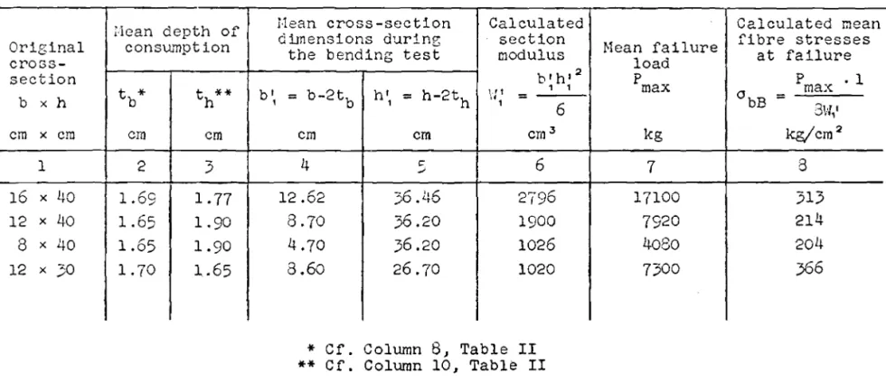
necessary to know the bending-strength values of the residual beam, which for various reasons will be less than that of the comparable, air-dry beam (in the present investigations the residual beams still showed some layers of charred wood; consequently strength in the compression zone at high tempera-tures was less than at room temperature). Table IV provides a basis for finding the strength of the residual beam in the present tests, according to which the extreme fibre stresses between 204 and 366 kg/cm2 (average value of
specimens with cross-sections 12 x 30 em, 8 x 40 em, 12 x 40 em and 16 x 40 em)
were obtained by calculation on the basis of the cross-section sizes as reduced by the measured depth of consumption.
For the folloWing calculation procedure, therefore, it was assumed that the residual beams, after exposure to fire for 30 minutes with temperature increase conforming to the standard temperature curve of DIN 4102, would withstand a bending stress a b,
=
180 kg/cm2 without breaking. It was furtherassumed that the unburnt beams were calculated with a maximum bending stress abo
=
100 kg/cm2 (allowable for softwood of quality Class II according toDIN 1052) under the design load. Let the section modulus of the cross-section for the unburnt beam be Wo' and that for the same beam after the described fire, W1 ; according to the requirement of DIN 4102, Sheet 1, the bearing capacity must be maintained under the design load for the full testing time; the maximum bending moment M before and during the fire test must be regarded as remaining constant. We thus have the relationship
whence
abo
\'11 ::; - - x \'l •
0b1 0
ilhereas the original cross-section dimensions were band h , at the end
o 0
or
DE
-14-(residual cross-section) with width b1
=
(bO -3.4)
cm and height h1=
(h - 3.9) cm (reduction of cross-section dimensions in each case by twice
o
the size of the measured consumption depth in the test). From the last equation we then have
( b - 3. 4 ) (h o - 3. 9
?
=
100 b h :2 o 180 0 0 (ho - 3.9)2 b=
6.12 2 • o 1.8 (ho - 3.9)2 - hoThis relationship permits calculation of the minimum width bo which must be present for a given height h
o under the described conditions if the beam is not to lose its ability to carry the design load in a fire of 30 minutes duration with temperature increase according to the standard temperature curve of DIN 4102. This relationship between width bo and height ho is clearly illustrated in Fig. 22. With decreasing height, as expected, the width of the cross-section required to satisfy the bearing-strength requirements increases. At heights of less than 20 cm this increase is so great that widths are obtained which do not occur in practice. For this reason there is no point in trying to satisfy the strength requirement with heights of less than 20 cm. For a 50 cm height the required minimum width is 10 cm, with only minor further reductions for greater heights. In practice, therefore, a width
of at least 10 em should be required even for large height in order to satisfy the strength requirement.
Summary
Glued laminated wooden beams with rectangular solid cross-sections between
8
x 20 cm and 16 x 40 em were produced with various artificial resin glues recognized as suitable for gluins structural bearing members of wood, and were exposed in the unprotected state to fire for 30 minutes as prescribed for the testing of fire-proofing structural menbers in DIN 4102, Sheet3,
B II. I (in two cases firing Has extended to a full hour). This was done in a gas-heated furnace. They were exposed to the fire on all sides as simply supported beams resting on two supports. During this test the temperature distribution over the cross-sections of the wood was followed. After the fire the specimens were subjected to a flexural test up to failure. Several
specimens were also SUbjected to deflection measurements under bending load both before and after the fire tests. From slices tal{en from certain of the test specimens, moisture distributions were determined over the cross-section after the fire test. Finally the reduction in cross-sectional dimensions was measured on all beams after the charcoal had been removed.
-15-After a half hour's fire testing of the specimens with 16 x 40 em
cross-section the breaking loads were on the average somewhat greater than two times the calculated design load (the latter calculated from the full cross-sections on the basis of a maximum bending stress ab
=
100 kg/cm2) .For the narrower cross-sections of 40 em height the ratio of failure load after the fire to design load was, as expected, less than for the 16 cm thick beams, whereas in the shallower cross-sections (12 x 30 em) again an average failure load of more than t.wLce the design load was obtained. The beams of 16 x 40 em cross-section which were subjected to a one-hour fire showed
failure loads of half the calculated admissible load. In all cases, the bond 「・エLセ・・ョ the glued laminations remained intact throughout the fire test.
AlthouC;h it was not possible to carry out the bending tests until ャセ to 2 hours after the fire test it may be assumed that beams would have behaved only slightly less favourably if loaded during the fire.
From the moisture distribution over the cross-section (measured immedi-ately on conclusion of the fire test) a migration of the moisture, as theo-retically predicted, from the Harm (outer) zones to the interior of the cross-section could be noted (peak values of moisture content up to 17%, at the centre of the cross-scctj_on only about 13%, corresponding to the mean moisture content established before the fire tests).
The temperatures wnLch were measured during and after the fire tests in specimens with 16 x 40 em cross-section clearly reflected the progress of
heating of the interior of the wood as a function of the time, was known in principle from the theoFJ of heat conduction and from numerous early papers by various authors. Of special interest in this connection is the fact that up to ャセ hours after the conclusion of the fire test there was a continuous rise in temperature in the interior cross-section zones.
The effects of consumption on the test specimens were surprisingly uniform. Thus during a 30 minute fire test the Hcic;ht loss per square metre of surface (specifiC consumed weiGht) was practically invariable at approxi-mately
6.5
kg/m:2, independently of the size of cross-section. The same applies to the reduction in vridth and heisht of the cross-sections; the mean depth of 」ッョウオセーエゥッョL measured laterally (half the reduction of the total width) was about 1.7 em for all specimens, the loean consumption depth in the vertical direction (half the reduction of the total height) was about1.9
em.From the conditions of the glued joints after the fire tests it was concluded that the resin glues with bases of resorcinol formaldehyde and urea formaldehyde have good stability in fire, even in the edge zones near the charred zones; some moderate decreases in quality found with one of the urea
-16-formaldehyde glues can be attributed to improper application (presumably too high a water content).
On the basis of the consumption depths obtained in these investigations and a maximum bending stress of 180 kg/cm2 in the burnt specimens remaining
after the consumed parts were removed (bending stress of the residual body in the loading test averaging between 204 and
366
kg/cm2) a diagram has been worked out from which the minimum cross-sections can be read such that after a half hourIs exposure to fire, with a temperature increase according to the standard temperature curve DIN 4102, they will retain their ability to support the full calculated design loads. In the authors' opinion this conclusion can confidently be applied to all domestic soft woods. In this connection, of course, it must be emphasized that wooden structural members which meet the mentioned strength requirement for fire-resistance according to DIN 4102, cannot pass as non-combustible since they burn. It would be welcomed if in revising DIN 4102, the narrow limitation that fire-resistant structural
-1'7-Table I
Deslgnations, dimensions, weights and moisture contents of test specimens immediately before the start of the fire tests
--Measured cross- Weight Moisture
Nominal sections content
Designa- before Unit of wood
Glue employed erOS8- the fire weight
tion section Width Height test kg/em3 before
em x em b h the test cm em kg
"
A I15.95
lJO.19
137.35
0.476
13.3
A2
Aerodux185
16.00
ItO.26
135.80
0. 1+68
13.7
A 316.01
1-1-0.30
134.10
0.465
16.0
w
116.01
40.02
132.35
0.459
13.6
W2
Kaurit W16.04
40.06
136.75
0.47
1-1- -W3
16
x40
16.02
IW.05
131-1- .50
0.467
19.0
WH6
15.68
1-1-0.50
125.65
0.445
14.0
WH7
Kaurit WHK15.70
40.'70
132.80
0.464
14.6
WH8
(White)15.78
40.80
130.50
0.452
13.4
WH9
15.65
1+0.60
127.30
0.447
14.0
K81
7.90
LtO .2064.20
0.1-1-51
12.7
K82
8
x40
7.80
ItO.20
63.85
0.454
14.0
K85
7.82
20.13
32.55
0.461-1-
12.8
K86
Kauresln8
x20
7.90
20.15
32.30
0.454
14.0
K121
440
11.80
40.30
91-1-.70
0.445
14.2
K122
12
x40
11.82
40.30
93.50
0.454
14.2
K 123
11.75
30.00
71.70
0.454
12.5
K 124
12
x30
11.'(9
30.00
74.40
0. 1-1-69
13.5
Table II
Consumed weights and depths and results of bending tests on glued laminated beams of various cross-sections
Consumed weight
I
Mean depth of consumption(loss of weight) Ratio
6h 6h P
t b ="2 t h ="2 Ca1cu- max
Pallo',; . Designa-I Original Duration Absolute Referred (From the (From the Failure 1ated
to 1 m2
tion of cross- of fire
of origi- width meas- height meas- load
permis-specimen section test urements) urements) Pmax sible
I
!'lean values
na1 Bur- load*
b x h Individual Mean face area vidualIndi- Mean vidualIndi- Mean Pallow.
セセセセセャ
I
PartialI
Fartial values values values values values values values total meancm x cm I min I kg kg kg/m2 em cm cm em kg kg 1 I 2 I 3 4 5 6 7 8 9 10 11 12 13
I
14I
15 A 1-
1.70 1.50 20400 8370 2.44 A 2 36.8 1.55 1.55 17720 8420 2.11I
2.31 A 3 30.7 1.45 1.10 20000 8440 2.37 'il 1 36.9 1.70 2.00 13920 3330 2.27 W 2 30 34.9 6.7 1.90 1.69 2.00 1.77 17320 3340 2.08 2.11I
2.05 I-
I-' \-IH 6 16 x 40 35.8 1.80 2.00 15440 3360 1.34 I WH 8 34.1 1.70 2.05 14320 3540 1.63 1.67 'ilH 9 35.3 1.70 2.00 12680 3390 1.51 ,,-1 3 78.3 3.90 5.35 4880 3340 0.59I
'.-lH 7 60 83.0 80.6 15.5 4.00 3.95 7.15 6.25 3760 8450 0.45 0.52 K 121 30.6 1.60 1.95 7760 6220 1.25I
K 122 12 x 40 30 31.3 30.9 6.5 1. 70 1.65 1.85 1.90 8080 6230 1.30 1.27 I K 81 27.9 1.60 1.95 4160 4150 1.00 \ K 82 8 x 40 30 28.0 28.0 6.4 1.70 1.65 1.85 1.90 4000 4100 0.93 0.99 K 123 25.0 1.70 1.65 5280 3430 1.54I
K 124 12 x 30 30 25.9 25.4 6.6 1.70 1.70 1.65 1.65 9320 3450 2.70 2.12 II I K 85 15.4 1.60 1.80-
-
-
I
K86 8 x 20 30 17.0 16.2 6.4 1.75 1.68 2.00 1.90-
-
-
-
I II
I
* Uniformly distributed load based on a b allow.=
100 kg/em2I
I
Table I I I
Results of deflection measurements on a ョオセ「・イ of glued laminated beams from flexural tests before and after exposure to fire
Deflection f at
100
kg/cm 2 extreme fibre stress Ratio ofreferred to the original cross-section* elastic f,1odulus of Ecfore exposure to fire After exposure to fire deflections elasticity
Cross- after the E,(before
Designation section fire tests exposure to
of specimen b x h Total Elastic Total Residual Elastic to those of fire)
deflection deflection deflection deflection deflection before
f'g f, e f 2g f 2b f 2e f 2e
em x em mm rom mm mm rom fIe kg/em2
1
2
3
4
5
6
7
39
1,m
68.9
8.9
17.8
1.0
16.3
1.39
101200
\lH8
9.2
9.2
21.3
0.9
20.4
2.22
95100
',m 9
16
x40
8.9
8.9
18.5
0.2
18.3
2.06
100600
i'lean values9.0
9.0
19.2
0.7
18.5
2.06
93900
K 122
12
x40
8.9
8.9
23.9
0.9
23.0
2.59
99300
K 81
8
x40
-
-
24.5
-
-
-
-K 123
12
x30
10.0
10.0
28.6
0.9
27.7
2.77
121900
*
Loads applied in accordance with Fig. 1I i-'
\0
Table IV
Calculated extreme fibre stresses (average values) in the bending tests after fire, based on the cross-section dimensions as reduced by the fire (taking into
account the depths of consumption)
cm I em
,
I\) o,
8 313214
201-1-366
Calculated mean fibre stresses at failure P max .1 3\'1,' kg/em2 °bB=
7 kg 17100 79204080
7300 Hean failure load Pmax 6 6 em? 2796 1900 1026 1020 Calculated section modulus b,
l h l 2,
'1'J1' = c= ..; em36.46
36.20 36.20 26.70 hI,=
h-2th*
Cf. Column 8, Table II**
Cf. Column 10, Table II em 4 Mean cross-section dilnensions durln8the bending test
12.62 8.70 4.70
8.60
b',=
b-2tb 1.77 1.90 1.90 1.65 2 I 3 tb*
I
th**
1.69 1.65 1.65 1. 70 Hean depth of consurnption 1 b x h em x cm Original cross-section16
x40
12 x40
8 x40
12 x 30 セセZセセZL[[LjI。M- -21-P • I セ TQNpNiセ ion . 't . J P • s セ Fig. 1
Disposition of load during a bending test of the specimen: In the formulae given W=
「セR
(section modulus)J
=
「セS
(moment of inertia) S=
「セR
(static moment) f=
elastic deflection Lure. cl.I'I'''e +loa セヲャNBL IlLLrition.,f. u-... l r "(,,.. r';:,Ss;s'ta.:t"Nウエイオ」セM *u...,tョ・エ。セtB ... I セ--
-:1,..;.:: I--セM--
---
_-::.:= ,..
t :-:5
セ-
セM IftIJ '7...
T) / IftIJ r, __i'-
-i-... 'I/; f--III f ! -I"'1
L - - --'''1-
/----f-
f -! - - _ Shndu-cl hml'""4 。・セHjイ、ャョb i o C"'JII
MMMセMM ::.=.-=.RaT'loBe.セ ー」ZイWGBウウゥセ ! - -! - - i::.emper.-ture de ......
I I -- f - - i - -1-- -I I 0-Duration of exposure. to fire.
Fig. 2
Standard temperature curve according to DIN 4102, Sheet
3,
Test set-up for exposure of beams to fire I I\) I\) 1 Se-ction A-B ---- Thermocouples Dimensions 1n cm upper}
lower measuring points
ェSQセZュヲjエャャ Gas and at r intake (burner) Secondary air intake
Cross-section F Fig. 3 Section C-D Section E-F Specimen Gas burners Gas bur-n-I-c
s
ers in rear half of furnace !Removable II
cover SpecimenJ
. I,AI
!
.
f'
Horizontal longitudinal section Gas burners on half of furnace situ-ated in front of section plane
-23-Lon.,;エセ、ゥ tid elevation
1
セQeZ]---'
t===-§ET
.-..."" { -I .... :. _ 1_ セf
i l i ' I J Fig. 4 Top: Below:Distribution of measuring points over the height of the beam
Distribution of measuring points over the width of the beam (dimensions in em)
>
-24-
1---t
--t--+--Sti'U',d...d temper"lure. Curve.
,a(..CQJ"'diltj(t., 0''''
4'04-Retrial")Nセ Ild-m;s., hie.
*e.mpe..,..tu,re tfe.v,a"Oh&
-l..-
f/./__ -il セ ! / / f--fr--f-+:"--r---j---t---!,--+---i--t---,--"1 - I / .,i
j---/-'7' /
,
;--
セiMMKMKMMKMMKMMMMMェ
H- - r - I-I I i I - t i !Ir---
-i--- ---
--i--t--t--r---11/00 °c '800 90n BOO 11J() Q.l H セHIHi ;::1 +> ctl >00 H Q.l 0-S .ro Q) E-t J(J(J ;rIO 1(1() ()
Duration of exposure to fire
Fig. 5
Curve of temperatures (mean values) in the furnace as a function of time
Fig.
6
cイッbウセウ・」エャッョ of specimen A 1 before the fire test (lett) and
after exposure to tire for 30 minutes (right).
The 」イッウウセウ・」エゥッョ at the right is taken
from above the support
Fig. 7
cイッウウセウ・」エゥッョ of test specimen W 2 before the fire test (left)
cB\AiBセ -S!'l"@"""
bend ...
e-.."'J!>tu»セ
-26-Fig.
8
cイッウウセウ・」エゥッョ of test specimen
WH
6 before the fire test (left)and after expoaure to fil"e for 30 minutes (right)
Fig, 9
Cross-section of specimens \'I!'H 8 and WH 9 after exposure
to fire for 30 minutes
AAセZZZZZNZ
,
-27-Fig. 10
Cross-section of specimen WH
7
before the fire test (left)and after exposure to fire for 60 minutes (right)
Fig. 11
Cross-section of specimen K 122 before the fire test (left)
and specimens K 121 and K 122 after exposure to
-28-!<'ig. 12
Cross-section of specimen K
81
before the fire test (left)and specimens K 81 and K 82 after 30 minutes exposure to fire (centre and right)
Fig. 13
Cross-section of specimen K 123 before the fire test (left) and specimens K 123 and K 124 after 30 minutes
Fig. 14
Cross-section of specimen K
85
before the fire test (left)and specimens K
85
and K
86
after
30
minutes
-)0-:rF '
--j-I
セ
:[
I
/-"H
180 - -1- --
セ。\Z[「セョ
セヲ
''--'- -.- --measu ring セセ ... セ 1---+-- - セ p01TltS In (;he cros-s» 160 -,edion (ef Fig"') I----.l----l-..j--+--r-140 l- - - - ...+-- +--+ ----1---1--+--+-+ I Cha.rred zone D'men.s;ons tn em oL- ...:....-_L..--'---J 1 5 10 15 3D4560 minDura,tio n ot f:.e.,.t 1 iセz J 5/)
F:Lg.
15
Temperature curve in speclmen WH 6 during and after 30 minutes exposure to fire. Measuring points
at various depths (in vertical direction) of cross-section
-31-スooセMMMセMNNNLNMMLMMᄋイMMイイMMイMMイMイMBLLMMLMMMNML °C e---I---+--+---+--t+-+-+-+-+--+---f----1 /tf}----
..
601---+--5 /0 /5 304560 rtvn DUNlion of test I /1111 3 5 10 18" Fig. 16Temperature curves in test specimen WH 7 during and after 60 minutes exposure to fire. Measuring points
at various depths (in vertical direction) of cross-section
-)2-200 °C
r
180 セ セ '\...
""Nセ 1'0 Q) 12 H ::l +> ro 100 H Q) 0-S 80 Q) 8o
lL----.LS--IOL-,SL--3-:':0:-":'S=-60':::'-.l-m..J.in---'---'Duration of test fly] 2 3 5h
Fig. 17
Temperature curves in test specimen v!H 9 during and after 30 minutes exposure to fire. Measuring points
at various depths (in horizontal direction) of cross-section
-))-セHjHI・
1\
no
\
1
c
80 Te-'jt Me 4 !!= - PbsitlOll...& セ
Specnnen co-ed ュセTaiNiNtGゥセ va'v..t.s pe,nf.S.-n セ 60 セセセ lC サQィZ[[セョZエャL ウセセAイKセAセセャ|セ I -0 セ 1\ i WH' A {Vt...エゥセBj t..f:ntr. _pl.,.@. '0 I \
WII7 0 (",el'"tk,z chreet. (lin) セ
1
\ \
Gセt
I 00 \ I I\
I 8 \"\ 60 \[\
:'\'
I :\
1\
セo セ| ',,\ I I -} iMセM.- .-
I--...
I 0 } セ 8 10 1} U em 1Dis!ance. from surface.. (depth)
Fig. 18
Temperatures in the interior of the wood after 30 minutes fire testing for specimens with 16 x 40 cm cross-section
(Position of measuring points on the two centre line planes in the longitudinal
"
o o 1] セ 1 Cha1"c.oal1Jyer (appro.lt. 4-em。セ・fv->
Ori«inal width bofihe.
crossMウセ、ェッャG|
I I I I I I I I I I I
'.'....,
\::'
'em6 4 } a }
DistaTlc.e. from the.veT-tic-OIl
CeTltre liTle ofセィ・N
c"1"oS.5-sed:ion }
a
,
III;
... III \) r: Charc.o.,l 1a1er la.ppT'CJN, iセB em 'deep) Iii "to セ 14 Fig.19
Distribution of moisture in wood over the croBs-section
after
30
and60
minutes exposure to fire(mean values) from several measurements
of specimens with
16
x 40 emFig. 21
Cross-section of specimen A 2 after
30
minutes exposure tofire (section of beam talcen above one of the
supports after ウ・。ウッョゥセァ for several
monthsi and exposure to st':nllght)
Minimum values of cross-sectional dimensions of supporting beams made of pine and fir which satisfy the bearing capacit:r
requirements for fire resistant structural parts according to DIN 4102 without
individual proof (suggestion for a
pertinent specification based