Publisher’s version / Version de l'éditeur:
Vous avez des questions? Nous pouvons vous aider. Pour communiquer directement avec un auteur, consultez la
première page de la revue dans laquelle son article a été publié afin de trouver ses coordonnées. Si vous n’arrivez pas à les repérer, communiquez avec nous à [email protected].
Questions? Contact the NRC Publications Archive team at
[email protected]. If you wish to email the authors directly, please see the first page of the publication for their contact information.
https://publications-cnrc.canada.ca/fra/droits
L’accès à ce site Web et l’utilisation de son contenu sont assujettis aux conditions présentées dans le site LISEZ CES CONDITIONS ATTENTIVEMENT AVANT D’UTILISER CE SITE WEB.
Research Paper (National Research Council of Canada. Division of Building
Research); no. DBR-RP-138, 1961-11
READ THESE TERMS AND CONDITIONS CAREFULLY BEFORE USING THIS WEBSITE. https://nrc-publications.canada.ca/eng/copyright
NRC Publications Archive Record / Notice des Archives des publications du CNRC :
https://nrc-publications.canada.ca/eng/view/object/?id=04cabf58-c81c-4aca-b468-65613764ee62
https://publications-cnrc.canada.ca/fra/voir/objet/?id=04cabf58-c81c-4aca-b468-65613764ee62
NRC Publications Archive
Archives des publications du CNRC
This publication could be one of several versions: author’s original, accepted manuscript or the publisher’s version. / La version de cette publication peut être l’une des suivantes : la version prépublication de l’auteur, la version acceptée du manuscrit ou la version de l’éditeur.
For the publisher’s version, please access the DOI link below./ Pour consulter la version de l’éditeur, utilisez le lien DOI ci-dessous.
https://doi.org/10.4224/40001495
Access and use of this website and the material on it are subject to the Terms and Conditions set forth at
An absolute thermal radiation calorimeter
A N A L Y Z E D
AN ABSOLUTE THERMAL RADIATION CALORIMETER'
'To allo\\~ the absolute calibration of field a n d laboratory radiomeless in the range 0.1 to 1.5 cal/cm2 sec, a continuous flow radiation calorimeter has been constructetl, based on a design originally developed by the Brilish Joint Fire Iiesearch Organization. T h e temperature dili'erence established bet\\zeeo a water outlet a n d a n inlet is sensed by a thermistor bridge and the radiation intensity measurement is made in terlns of the level of t h e electrical power, applied t o a built-in immersion heater, which is necessary to reproduce the same temperature dilference.
Radiative heat transler is an important mechanism of fire spread, particu- larly from one building to another, and although much inforlnatio~l is already available on this question, new problems continually arise. T o pennit further studies by the Fire Section of tlle Division of Building Iiesearch, National Research Cou~icil, it has become essential to be able t o measure appropriate levels of radiation intensity.
'The lower limit of the range involved is associated with the threshold intensities a t whicll colnlnon materials will ignite. Results already obtained by the Britisli Joint Fire Research Orga~lizatio~i show that pilot ignition (i.e. ig~iitio~i ill the presence of a small flame one inch or so from the irradiated surface) will occur a t 0.15 cal/cm2 sec for fiberboard and a t 0.3 cal/cm2 sec lor wood and many other cellulosic materials. The lower limit of tlle desired range is thus of the order 0.1 cal/cm%ec.
The upper limit is deternlined by the feasibility of protecting materials so as to increase the threshold levels of intelisity a t whicli ignition will occur. British work on the effect of fire retardant paint on fiberboard has shown t h a t the tlireshold intensity for pilot ignition call be raised to 1.0 cal/cm2 sec. If the effect of the treatment 011 timber were to increase the threshold inte~isity for
ignition by the same factor, whicli is unlikely, i t might be thought that investi- gations with i~ite~isities of the order of 2 cal/cm2 sec would be essential. Experimental ~neasurelllents carried out during building fires, however, show t h a t such a n investigation is not immediately called for. Although the radiation levels a t window openings in buildi~ig fires call rise to as much as 3.6 cal/cm2 sec, levels rarely exceed 1.5 cal/cm2 sec a t ranges beyolid which flames will not be expected to extend. Flame iliipi~ige~ne~lt is likely to give greater levels of heat transfer than a radiation Ievel of between 1.5 and 3.6 cal/cm%ec, and a s f a r as the protection of materials is concerned the effect of flame impi~lgeme~it is thus the more interesting subject for investigation. Tlie upper limit of radiation intensity required to be covered by the Fire Section's i~lstrument was therefore set a t 1.5 cal/cm%ec.
'Manuscript received July 29, 1061.
Contribution from the Division of Building Research, National Research Council, O t t a w a , Canada.
Issued a s N.R.C. No. 6534.
Can. J. Pllys. Vol. 39 (1961)
1584 C.\iX.-\DIAS J O U R S A L O F PIIX-SICS VOL. 39. 19(il
Suitable field and laboratory radiometers have been constructed for the use of the Fire Section but no calibration facilities have been found con- veniently available. I t was therefore decided to construct an absolute radio- meter for the calibration of radio~neters in the range 0.1 to 1.5 cal/cm2 sec.
CI-IOICE O F ISSTRVAIEN'I'
When the British J.I;.I<.O. began its morl; on the ignition of materials bj- radiation in tlie earlj- 195O's, it was faced with the same problem of lack of calibration facilities and had to develop its own design of absolute radiometer
(Lawson and YIcGuire 1'353). The instrument is of the continuous flow calori- nietric type, and measurement is made of tlie electrical power required to produce the same eq~~ilibrium tenlperatul-e conditions as are producecl by the radiation level in question. The instrument lias proved reliable and sufficiently accurate to meet tlie needs of fire research.
Before adopting this design a literature surve). was carried out to determine whether any other type could be a s readily constructed. It soon became apparent tliat little or no interest has been shown in the past in the nleasure- ment of infrared radiation levels in the range 0.1 to 1.5 cal/clli2 sec.
T h e instrument which comes nearest to meeting the requirement is that used by Coblentz (1915-1916) a t the National Bureau of Standards during the First World War. I t consists basically of a blackened electrical corrducting strip, behind which is mounted a radiation thermopile responding to thermal radiation from the back of the strip. T h e first step in measurement is to recorcl the output of the thermopile when tlie blaclcened strip is exposed to a level of radiation. Radiation is then cut off and electrical heating of the strip substitutecl. When the level of the electrical heating has been adjusted to produce the same output from the radiation ther~iiopile, the electrical po\iIer input is taken as a measure of tlie radiant flux which was previously incident on the strip. Coblentz was undoubtedly using a radiation source with a
temperature of tlie same order as tliat of the radiant panel used for the experi- mental fire work carried out a t N.R.C. T h e nature of his instrument, however, indicates that the level of the intensity which he measured was very much lower than tlie intensit?. near his source. Altlio~~gli it was the object of his worl; to determine the intensity a t the source, he derived this by tlie inclusion in his expressions of a very substantial geometrical factor.
T h e accuracy of the instrument, a s used by Coblentz, involved very careful assessment of the relative areas involved in the heating, both bj- radiation and by electric power. If the instrument were redesigned to allow direct measurement of intensities within the range 0.1 t o 1.5 cal/cm2 sec, the strip and thermopile would become very sensitive to draughts. Worl; on the develop- ment of field anel laboratory radiometers a t N.R.C. has already shown tlie magnitude of this problem. After conlparison of these problems wit11 those associated with the J . F . R . 0 . design it was decided not to proceed with tlie Coblentz approach.
I n 1937, Guild described a temperatul-e drift radiometer used for a lower range of intensities. I t is thought, however, tliat tlie temperature drift
b I c G V I K E : R.\DI.\TlON CALORIMETER 1585
technique can only be considered superior to a continuous flow calorinietric approach when tlie range of intensities is so low that tlie temperature differences associated with the latter technique are too s ~ u a l l to allow accurate Ineasure- ment. No si~nple alternative approaches being available, it was clecided to construct a constant flow calorimetric type radiometer.
The apparatus is of the continuous flow calori~netric type, using water a s tlie coolant fluid; radiation incident upon tlie calorimeter produces a tempera- ture difference between tlie water inlet and outlet. A~Ieasurement is made i n terms of the electric power \~~liich must be supplied to all inimersion heater to reproduce this same temperatiire difference. This technique substantially eliminates errors associatecl w~itli the various incleterniinate heat losses.
The essential component of tlie apparatus is illustrated in Figs. 1 and 2. It consists of a calorimeter sul-1-ou~ided by a water-cooled guard ring \vliicli ensures that the incident radiation, the level of \vhich is to be measured, falls only on tlie front face of the calorimeter. Factors determining tlic dii-nensio~~s of the calorimeter are discussed in Appendix A ; they are primarily associated with the source of radiation used, a gas-fil-ed I-adiant panel 1 f t sq. T h e dimen- sions of the guarcl ring are not critical b u t nli~st be adequate to ensure t h a t vat-ious components and pipeworl; behind the calorimeter are shieldecl from radiation.
A constant rate of flow of water is establisliecl in the calorimeter by the self-
CXN.-\DI:IN J O U R N X L O F PI-IYSICS. VOL. 30. 1961
'<TO W A S T E
S E C T I O N AT C A L O R I M E T E R
17rc. 2. Radiation calorimeter.
stabilizing arrangement illustrated in Fig. 2. Variations in t h e hydraulic resistance of the calorimeter and its associated feed system can only give rise to transient variations in the flow and cannot influence the eqi~ilibriurn rate of flow. T h e vent illustrated in Fig. 2 was included to eliniinate air locks in the system.
T h e temperature difference which is established between the water inlet and outlet is sensed by the two thermistors illustrated in Fig. 2. T h e function of the length of tubing between the calorimeter and the outlet ther-niistor is
to ensure adequate mixing of tlie heated water. Prcviously it liacl been founcl that when the thcl-mistor was located very near the calorimeter it gave fluctuating readings. 'l'he design of the thermistor briclge, together with tlie choice of rate of flow of water, which is a related clecision, is ~liscussed in Appendices
B
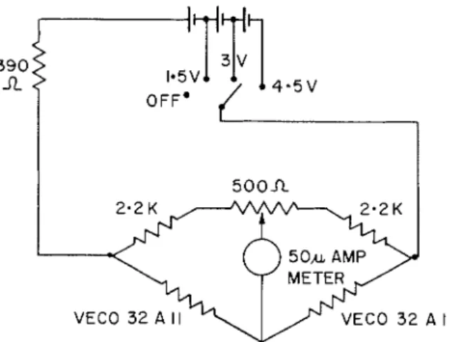
and C. T h e circuit is given in Fig. 3.Co~isiderable care was talcen to ensure that the differential se~isitivity of the bridge was not substantially influe~lcccl by variatio~is in the ambient temperature of the inlet water. This was achieved partly by the design of the bridge, as discussed in Appendix
C,
and partly by shielding the water supply piping as is illustratecl in Fig. 1.T h e electrical i~nrnersion heater i~lcludecl in the calorinleter consists of No. 26 B and S Nichrome A wire wound on a plexiglas forn~er. I t s resista~lce is approximately 7 ohms. Electrical power is supplied by a lead-acid battery.
A choice of several battery potentials between G and 36 volts is available and
McGUIRE: RADIATIOK CALORIMETER
VECO 3 2 A I l VECO 32 A I1
FIG. 3. Circuit diagram of thermistor bridge.
differeilces are measured with precision electrical ineters and the coililections between the voltineter and the i~nnlersion heater are separated from the power leads t o ensure that the poteiltial difference measurement relates t o t h e inlmersion heater proper and does not include the potential drop in the power supply leads. No correction is called for a s regards the power coilsumption of the voltmeter as it only amounts to a small fraction of 1 per cent of t h e ineasured power consumption.
T h e electrical instrumentation associated with both the immersion heater and the thermistors is housed in a single unit.
1'ERFORhI:lNCE 01; TI-IE Cr\I.ORIMErrER
The apparatus has been used to calibrate several of t h e Fire Section's radiometers in the range 0.1 t o 1.2 cal/cm? sec and a typical calibration is show11 in Fig. 4. The response time of the thermistor bridge has been found
O U T P U T m v
1588 C , \ S . \ D I A JOURS.\L O F PIIYSICS. VOL. 39. 1961
to be about 90 seconds, and a measurement including the substitution of electrical for radiant heating call be completed in 3 minutes.
Contrary to expectations no problems resulting from air coming o u t of solution from the mater were e~icouiltered during the course of a measurement. This probably resulted partly from the use of a wetting agent i l l the water to
reduce the liltelihood of the for~natioil of large bubbles and partly froill the fact that the time constant of the meter incorporated in the thermistor bridge circuit was about 10 seconds so that ally short-term fluctuatiorls were inte- grated.
T h e variability of measurenients wit11 the calorimeter is sinall and has in fact proved difficult to measure. NO assessment can be made froin the cali- bration given i l l Fig. 4 as the variability in this case could be largely attributed
to the radiometer. Total radiation p).rometer measurements also indicate that the level of radiation emanating from the panel is not sufficieiztly coilstant to allo\v a reasonably accurate direct determination. T h e variability is of the order 1%, and for the calibration purposes for which the caloriineter is required this factor becomes ~lnimportant, first because a calibration is bound to iilvolve a number of measurements and secondly because the absolute error associated with the instrument is of the same order.
SOUliCES 01; E R R O R
The principal, ailcl in fact the only, appreciable source of error lies not wit11 the use of the apparatus but in the value assuilled for the e~nissivity factor of the receiving surface of the calorimeter. No measurement can be inore accurate than the accuracy to ~ v l ~ i c h this quantity is l t 1 1 0 ~ 1 1 and if an incorrect
value were assumed, the use of the apparatus would give no indication of it unless the assumed value were in error by a t least 10%.
T h e surface in questioil has been coated with carbon blacli, the emissivity of which is not greatly dependent 011 the wavelength of the incident radiation
and is high so that the greatest possible water temperature differential is established. I-Iottel (Chemical Engilzecrs Handbook 1950; Stoever 1941) has reviewed einissivit)~ measui-ements and gives the value for caildle soot as 0 . 9 5 f 0.01. I t agrees substai~tially with the results of Coblentz's ~vorlt (1913a, b, 1915-1916) earll~ in the century. Although I-Iottel's figure is given to an accuracy of 17, it is possible that the practical clifficulties of applying the coating to the calorimeter surface give values of emissivity that may differ from the above by say 2%.
The oi11y other basic source of error in the apparatus would lie in the measurement of the electrical pon7er but since this merely involved the measure- ment of d - ~ . voltage and current it can be coilsidered reliable.
Sources of error associatecl with the small heat losses from the inner calori- meter to the atmospl~ere and to the outer calorimeter are reduced to a very low order by the measurement technique of substituting electrical power equal to the level of radiant energy received. T h e magnitude of the heat losses must correspond closely when the same rates of energy are supplied either by radiant heating or by the electrical heater immediately behind the front face of the inner calorimeter. T h e thicltness of the front face, which is
McGUIRE: R.ADI.lTION CALORIMETER 1589
of copper, is sufficiently small that no appreciable temperature differences are ever established across it. Different cooling conditions could arise owing to the fact that the outer guard ring is irradiated only when the heating is b ~ , radiation. T h e flow of water through this guard ring is sufficiently great, however, that the radiant heating does not establish any appreciable tempera- ture difference between the water outlet and inlet.
I t is nevertheless desirable that the extraneous heat losses from the inner calorimeter should not be of the same order of ~nagnitude a s the heat transfer by mass flow of the coolant water and this question was investigated experi- mentally by injecting a known level of electrical power and comparing it with the heat dissipation via the water. T h e temperature difference between the water outlet and inlet was made with differential thermocouples rather than with the thermistor bridge, which has never been calibrated. To reduce the effect of stray thermal e.m.f.'s, which can be significant when using thenno- couples to measure small temperature differences, and to maximize the extraneous heat losses being investigated, a high water temperature difference was established by using a high power input and a low water flow. With a temperature difference of about 20" C, a t least five times higher than the ~ ~ s u a l nlaxinlum, two measurements gave the ratio of the heat flow via the water to the heat input a s 95.4 and 98.3y0. The accuracj- involved in the experimental method is obviouslj- poor but the results justify the conclusion that the extraneous heat losses are small.
As discussed earlier, the sensitivity of a ther~nistor bridge can be dependent on ambient temperature. This could introduce error associated with pre- heating of the supply water to the inner calorimeter when it is exposed to radiation. T o eliminate this source, care has bee11 taken t o ensure t h a t the inlet water supply is carefully shielded from radiation ~ ~ n d e r both sets of heating conditions. I n addition, the thermistor bridge has been designed to reduce the dependence of the differential sensitivity on the ambient tempera- ture of the water.
CONCLUSION
The radiation calorimeter described in this report permits the calibration of a radiometer in the range 0.1 to 1.5 cal/cm2 sec, sing a gas-fired panel
1 ft sq. a s a source of radiation.
The accuracy of the apparatus is of the order of 2% and the variability of readings is lower. A better knowledge of the emissivitjr factor of the receiving surface would improve the accuracy.
Acknowledgment is due t o
P.
I-Iuot of the Fire Section for the construction of the apparatus described in this report and for helpful advice on the elimi-nation of various unforeseen technical problems.
R E F E R E N C E S
CHEMICAL EXGIXEERS ~IASDBOOIC. 1950. (McGraw-Hill), p. 485.
COBLENTZ, 11'. W. 1913n. T a t l . Bur. Standards Bull. 9, 283.
1590 C A K A D I A N JOLRXAL O F PHYSICS. VOL. 39, l9Gl
COBLENTZ, I.\\ W. and ELIRRSON, W. B. 1915-1916. Natl. Bur. Standards Bull. 12, 503. GUILD, J . 1937. Proc. Roy. Soc. Ser. A, 161, 1.
LAWSON, D. I. and M C G V I I ~ E , J . H. 1953. A radiation calorimeter for the absolute measure- ment of radiation intensities between 0.4 and 12.5 watts/cm? Joi~int Fire Research Organization (D.S.I.R. and F.O.C.), Fire Research Note KO. 37/1963, March 1953. MCGUIRE, J . H. 1053. I-feat transfer by radiation. Dept. of Scientific and Industrial
Research (DSIR) and Fire Offices' Committee, Fire Research Special Report KO. 2, H.M.S.O. London.
STOEVER, H. J . 1941. Applied heat transn~ission (McGraw-Hill), Table IV, p. 214. A P P E N D I X A
The radiation calorimeter is used t o calibrate radiometers which have a
receiving area only $ in. in diameter. The radiation calorimeter lneasure~llents must therefore refer t o such a small area.
For co~lvenience in the coilstruction of the calorimeter a larger receiving area is desirable and the variation of the intensity over a larger area must therefore be investigated. The apparatus will be used in conjunction with a radiant panel 1 ft sq. Configuration factors relating t o rectangles are, how- ever, cumbersoine and both radiating and receiving areas will therefore be assumed t o be plane disks.
Using the nomenclature
R = radius of radiating disk,
mR = radius of receiving disk, and
nR = separation between the two disks, the two disks being normal to a common axis,
the integrated co~lfiguration factor F relating the two disks is (McGuire 1953):
Assuming that m
<<
1, the expression approximates toThe mean configuration factor a t the receiving disk, relating t o the nzean intensity, will thus be
The configuration factor on the axis will be
f3 will relate to the field radiometer to be calibrated for which the value of nz,
when used in conjunction with the radiant panel 1 ft sq., will be very small. T h e fractional error in the intensity nleasure~lle~lt due t o the finite area of the calorimeter will thus be
Since this error is a function of n which must essentially remain a variable, the application of a n error correction woulcl be inconvenient. I t ~voulcl b e more convenient t o ensure t h a t the error is always small.
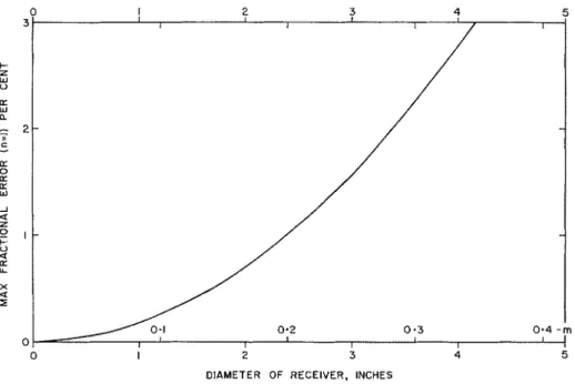
Differentiation of the above expression shows that the error will bc greatest when n = 1 and consideration of the temperature of the panel and the radiation level required shows t h a t this position will be used for calibration purposes. This condition has therefore been assumed in calculating the error which is shown in Fig. 5.
T o ensure t h a t the error is appreciably less than 1% it is thus desirable t h a t the dimension of the receiving surface should not exceed 2 inches.
FIG. 5. Measurement error introduced by hnite area of receiving surface.
A P P E S D I S B
T h e design of the t l ~ e r ~ n i s t o r bridge is d e p e ~ l d e n t on t h e range of tenzperature difference to be established between t h e water inlet a n d outlet of t h e calori- meter. I t was decided t h a t this should lie within the limits 1"
C
a n d 10"C,
the lower linlit being set b y considerations of the accuracy of differential temperature illeasurelnent and the upper linlit b y the desirability of elirninati~lg possible second-order effects of stray cooling. First-order effects of straj- cooling are already eliminated b y t h e adoption of the electrical power substitution method of measuring the radiant intensity. I t was thought that water flows and temperature differences could be maintained within t h e linlits given in Table I.
1592 C A S A D l h N JOURN.4L O F PHYSICS. VOL. 39, i n c j l
\\;ater flo\v and t e r n p e r a t ~ ~ r e difference ranges
-
Radiation intensity \\.ater flo\v T e m p e r a t ~ ~ r e difference
Limit (cal/cm2 sec) (cc/ser)
("c)
Upper 1 . 5 10 4.0
Lower 0 . 1 1 . 5 1 7
T h e most appropriate measuring circuit in which the two thermistors can be incorporated is the simple Wheatstone's bridge as illustrated in Fig. 6.
(THERMISTOR)
(THERMISTOR
FIG. 6. \\'heatstone's bridge.
T o simplify the expression for sensitivitj- it has been assu~lled t h a t the tlzermistors are perfectlj, matched and that a t ambient temperature the four arllls are of equal resistzulce. Some improvement in sensitivity a t the expense of power consu~nption could be achieved by the s u b s t i t u t i o ~ ~ of low resistances in the two upper arllls of the bridge.
T h e sensitivity of the bridge of Fig. G is given bl-
\vhere the significance of the symbols is indicated in Fig. - 6.
T h e power dissipation in the thermistors must be limited t o some value
W
such that the temperature \vill not be raised excessivel>r b!, ohmic heating. This dissipation is given to a close approximation b yW
= E"4li. Substituting for E, in the expression fori,,
givesIn general, therefore, - if r, is not of a higher order than li, the briclge will be lllore sensitive for loxver values of R.
MCGUIRE: RADIATION CALORIMETER 1593
A convenient thermistor for this application is the Veco 32411 thermistor with a resistance of approximately 2 kfl a t 25"
C
and a dissipation constant of about 5 ni\v/"C tei~lperature rise under the flow conditions considered here. If a temperature rise of 0.4"C
is acceptable a dissipation of 2 niw can be tolerated.Using a 50-pa meter witli a resistance of about 1.8 kfl, the current values t o be expected for the conditions discussed above ancl tlie two extremes of radiation intensity listed in Table I are 37 pa and 17pa.
T o realize a practical briclge a 500-ohm potentiometer was included in the upper arm of tlie bridge, as shown i l l Fig. 3, to allow balancing of the bridge.
T h e circuit of Fig. 3 also includes a resistor in series witli the battery. T h e function of this resistance is cliscussed in Appendix C.
REDUCTION O F THE EFFECT O F AMBIENT TE~IPEIIXTURE 'The resistance of a thermistor can be approximately represented by the expressioii
2 = a e b l T .
Where one particular type of thermistor is considered, e.g. the Veco 3 2 A l 1 ,
the value of b does not vary greatly between thermistors. Tliis being so, it is to be expected that variations in ambient temperature will not greatly affect the zero I-eading of a bridge of the type illustrated i ~ i Fig. 3. I t is, of course, important that tlie set zero potentiometer should be locatecl a s illustrated.
\/it11 a view to reducing the dependence of differential sensitivity o n tel-nperature consicler the inclusion of a resistor S i n series with the battery as sliowl~ in Fig. 7 .
The expression for tlie sensitivity is EIZ ( 2 1 - z ? )
I p =
( Z ~ + Z ~ ) ( . ) Y ~ ~ ~ + R ' + S R + S Y ~ ) + z ~ z ~ ( ~ ) R + S ) + R S ( J Z + ~ ~ ~ ) a
1594 CASADIXK JOURNAL O F PHYSICS. VOL. 38, 1861
Substituting el = aeblT and z2 = ~ e ~ l ( ~ + O ) and malting the approximations
arid
Differentiating with respect to
T
and equating t o zero gives the condition - ~ R z ~ ~ + ~ ~ , R ~ ~ + ~ R ~ T z + ~ R T z 's
=be' - 2%' - -1TzX - 4Tzv, - bli" 2Rbr,
-
~ R ' T - 4r,Iil' where e = aeuT.111 the bridge under discussion
R = z = v, (at normal operating temperature) maliing these approximations
Substituting the numerical values
R
= 2 liG, b = 3,493" I<, and 1' = 300" I<, S = 372 R.Inclusion of a resistor S = 372 D should therefore, a t temperatures in the region of 27"