Publisher’s version / Version de l'éditeur:
Vous avez des questions? Nous pouvons vous aider. Pour communiquer directement avec un auteur, consultez la
première page de la revue dans laquelle son article a été publié afin de trouver ses coordonnées. Si vous n’arrivez pas à les repérer, communiquez avec nous à [email protected].
Questions? Contact the NRC Publications Archive team at
[email protected]. If you wish to email the authors directly, please see the first page of the publication for their contact information.
https://publications-cnrc.canada.ca/fra/droits
L’accès à ce site Web et l’utilisation de son contenu sont assujettis aux conditions présentées dans le site LISEZ CES CONDITIONS ATTENTIVEMENT AVANT D’UTILISER CE SITE WEB.
Internal Report (National Research Council of Canada. Division of Building Research), 1962-02-01
READ THESE TERMS AND CONDITIONS CAREFULLY BEFORE USING THIS WEBSITE.
https://nrc-publications.canada.ca/eng/copyright
NRC Publications Archive Record / Notice des Archives des publications du CNRC :
https://nrc-publications.canada.ca/eng/view/object/?id=9b90a080-bdf1-4c09-80c9-ec2d4a702b49 https://publications-cnrc.canada.ca/fra/voir/objet/?id=9b90a080-bdf1-4c09-80c9-ec2d4a702b49
Archives des publications du CNRC
For the publisher’s version, please access the DOI link below./ Pour consulter la version de l’éditeur, utilisez le lien DOI ci-dessous.
https://doi.org/10.4224/20338089
Access and use of this website and the material on it are subject to the Terms and Conditions set forth at
Trial of specification tests for forestry fire hose
NATIONAL RESEARCH OOUNOIL
OANADA
DIVISION OF BUILDING RESEAROH
TRIAL OF SPEOIFIOATION TESTS
FOR FORESTRY FIRE HOSE
by
G. Williams-Leir and R. D. Stagg
ANAt YZED
Internal Report No. 240 of the
Division of Building Research'
OTTAWA
The Division of BUilding Research has recently co-operated with the Canadian Government Specifications Board in a revision of its speoification for unlined forestry fire hose and the preparation of a new one for
ャゥセ・、 hose. Certain measurements on lined hose were
requested by the Board's Committee on Fire Hose to guide them in drafting the specification. Now that both
セー・」ゥヲゥ」。エゥッョウ have been published, a series of tests on
both types of hose has been completed.
All readily available brands of hose on the
Canadian market were tested. Though none was found to oomply with every requirement of the specifications, it should be borne in mind that these were hoses manufactured either to a different specification or to none at all. Now that manufacturers know the exacting requirements that their
products should meet, it is confidently hoped that they will be able to produce hose that complies.
The authors are a research officer and a technioian with the Fire Section of the Division.
Ottawa
TABLE OF CONTENTS
PAGE
SECTION 1.
PRESSURE AND LEAKAGE
1.1 Modes of Failure in Pressure and
leakage 2
1.2 Cause of "Final" Failure of Hose
7
1.3 Leakage Measurements 9
1.4 Twist, Rise and Warp 11
1.5 Elongation 12
SECTION 2.
HOSE CONSTRUCTION
2.1 Jacket Materials Used 2.2 Diameter
2.3 Weight and Flexibility 2.4 Bonding of Lining
SECTION
3.OTHER REQUIREMENTS
3.1 Heat Resistance
3.2 Aging of Hose Lining 3.3 Acidity
SECTION
4.
SUMMARY
ACKNOWLEDGMENTS
13 14 1516
17
18 20 21 26by
G. Williams-Leir and R. D. Stagg
The cッセセゥエエ・・ on Fire Hose of the Canadian Government
Specifications Board has prepared Specifications 13-GP-lb for "Hose; Forestry, Unlined," and 13-GP-2 for "Hose; Forestry,
Lined." T'nese specifications differ considerably from their
predecessors, and prior to the work described in this report, no tests had been made in exact accordance with them.
The objective of this work was to ascertain whether the specifications are sufficiently severe to distinguish
between good and bad products, and to ensure that, in so doing, they do not disqualify all, or nearly all, hose in current
production. The work was started while the specifications
were still under discussion, and the early results on lined hose, presented in an interim report (l) were submitted to the committee before the final version of the lined hose specification had been approved.
Certain observations were made, and are here reported, beyond those which the current versions of the specifications require; some of these were called for in earlier drafts of the specifications and have since been discarded, ahd others have never been required.
Through the kindness of Mr. J. C. Macleod, Joint
Secretary of the Associate Committee on Forest Fire Protection,
specimens of hose, as listed below, were obtained. The 15
brands, A to I and P to U, are those to which the
specifica-tions apply. Six other brands to which they were not
applicable were also included. Requirements of the
specifi-cations that are inappropriate to the type of hose have been
indicated in the tabulation of results. The 21 brands have
been coded; the code will be disclosed only to the Secretary of the Committee on Fire Hose of the Canadian Government Specifications Board.
No. of Brands Type Nominal Diameter, Code
in. 9 lined ャセ A-I 4 lined 1
J-M
2 lined, plastic-coated ャセL Rセ N-O 6 unlined ャセ P-U(l) Stagg, R. D. and G. Williams-Leir. Trial of a proposed
method of test for forestry fire hose. National
Research Council, Division of Building Research,
2
-The specifications are frequently paraphrased or quoted in this report, but for the exact requirements the reader should refer to the originals.
NOTE ON TERMINOLOGY
Rupture means bursting of the hose.
Failure includes any deficiency in respect of the specification requirements, and is also used for rupture or coupling separation even when the specification requirements are met, i.e. when rupture etc. occurs above 600 psi.
In the tables, distinction is made between failures to meet the specification requirements and cases when a test could not be applied because of some earlier failure, e.g., it is not possible to measure leakage at 200 psi if a hose ruptures at 150 psi.
SECTION 1. PRESSURE AND LEAKAGE
1.1 Modes of Failure in Pressure and Leakage
The ways in which a hose can fail to meet the re-quirements relating to the bursting pressure and leakage test are as follows:
Rupture of weft fibres. Rupture of warp fibres.
Small pinholes where it is not possible to detect which fibres, if any, have ruptured. Excessive leakage.
In the use of lined hose, a small pinhole in the lining, which may show up as a Itwet patch. It
Slipping or tearing at a coupling. This
indicates either that the coupling has been imperfectly attached to the hose, or that the hose has been weakened by com-pression between the coupling and the expansion ring.
In the tables that follow, the mode of failure of each hose is tabulated.
Unlined Hose Requirements
Four specimens are to be tested, two of which
to be subjected to leaching in running water at 15°C for
7
for 14 days. After this they are subjected to a pressure test.
The pressure schedule for all four specimens was
as follows. (All pressure increases were at the rate of
100 psi per min.)
Firstly, measure the length when dry.
At 0 min. fill hose with water at 10 psi and measure
the length.
1 raise pressure to 100 psi and hold.
17' start to collect leakage.
RWセ
stop collecting leakage. Measure length,tv/ist, etc.
28 raise pressure to 200 psi and hold.
291 start collecting leakage.
SYセ
stop collecting leakage. Measure length,twist, etc.
40 raise pressure to 300 psi and hold.
41 measure length, twist, etc.
42 raise pressure to 600 psi and hold.
451 start collecting leakage.
551 stop collecting leakage. Measure length,
tv/ist, etc.
56 raise pressurE; to failure of specimen.
The requirements state that
leakage at 100 psi must not exceed 3.4 ml/ft of length/min.
14.2 ml/ft of leakage at 200 psi must not exceed
length/min.
142.0 ml/ft of leakage at 600 psi must not exceed
length/min.
the hose must withstand a pressure of 600 psi for 10 min.
Lined Hose Requirements
Three specimens are to be tested; all are to be
subjected to leaching in セjョョゥョァ water at 15°C for 7 days.
They are then to be placed in cold storage at -18 +2°C for
24 hours, followed by flexing. After soil burial In loops
totalling 4.0 +0.5 ft for 14 days, the pressure schedule for all three specImens shall be as follows:
Firstly, measure the length when dry.
At 0 min.
1 4
fill hose with water, bleed off any air, raise pressure to 10 psi, hold, and measure length, twist, etc.
raise pressure to 300 psi and hold. measure length, twist, etc.
-5 8 13
4
-raise pressure to 600 psi and hold. measure length, twist, etc.
raise pressure to failure of specimen.
The requirements are: no leakage or wet patches
at any pressure up to and including 600 psi, and, 600 psi for
5 min
2:
10 sec.Test Results and Analysis
TABLE I
FAILING POINT* OF SPECIMENS
Brand Pressure, psi
Test 1 Test 2 A 300 300 300 425 500 425 B 600 300 600 525 500 500 C 300 220 325 150 100
-D 500 500 450 375 400 400 E 925 950 950-
-
-F 300 260 360 275 260 240 G 750 750 725 600 750 600 H 875 850 775 775 825 750 I 575 575 500 600 600 -J 875 500 1080-
-
-K 825 780 725-
-
-L 400 450 600-
-
-M 110 425 300-
-
-N 520 470 520-
-
-a
530 575 550 500 600 580 P 600 600 700 850 860 200 200 200 Q 800 200 600 600 100 640 740 -R 60 100 575 200 95 95 540 -S 200· 200 100 200 200 200 100 -T 100 100 525 600 100 100 600 600 U 100 100 975 200 100 100 100--:to The term IfFailing PoLnt " is used here to denote the first
point at which the hose fails anyone of the specification
requirements for pressure or leakage. See the Note on
TABLE II
MODES OF PRIMARY FAILURE
UJ Mode of failure at or below 600 psi Above 600 psi
s::
0)
S
.,-/
0 {f) rJ) {f) rJ) {f) {f)
0) Cf.-to) Cf.-to) 0) ..p ..p ..p Cf.-to) Cf.-to) 0)
A OH OH .t:: co co co {f) OH OH .t:: {f)
UJ .0 .0 0 {f) bD ,0 .0 0 {f) eo
o)..-! 0).,-/ ..p a> a> a> a> s:: a>0,-/ a>.,-/ ..p a> s::
Cf.-tro セcヲNMエ HCf.-t co n eo eo bD 0,-/ HCf.-t HCf.-t
セ n ..-!
ro 0 0 ) ::s A 0 co
セ セ n ::s ::s 0 n
s:: ..p ..p..p ..pp..
.g
セ A ..p..p ..pA{l
c,セ • UJ aセ AH ..p COO cao coO ::s Aft; AH ..p ::s
o a> ::Sa> セセ Q) .,-/ a>0 a>0 a>0 0 ::s a> ::Sco a>
セ 0
セ セNNー IZ?; E5: Poi Hn HC\J H\.O 0 IZE: P:iE: セ 0
A 6 2 -:. 3 1
-
-
- -
-
-
- -
-B 6-
3 3-
-
-
- -
-
-
- -
-c
5-
4-
1-
-
-
-
-
-
- -
-D 6 1 3-
2-
-
- -
-
-
- -
-E 3-
-
-
-
-
-
- -
1 2- -
-F 6-
6-
-
-
-
- -
-
-
-
-
-G 6-
-
2-
-
-
- -
1 2-
-
1 H 6-
- -
-
-
-
-
-
1-
- -
5 I 5 5- -
-
-
-
- -
-
-
-
-
-Subtotal 9 49 8 16 8 4-
-
- -
3 4-
-
6 J 3-
-
-
-
-
-
-
1 1-
-
-
1 K 3-
-
-
-
-
-
-
-
1-
-
-
2 L 3 3- -
-
-
-
- -
-
-
-
-
-M 3 1 1-
1-
-
- -
-
-
- -
-Subtotal 4 12 4 1-
1-
-
-
1 2-
-
-
3 N 3 2- -
-
-
-
-
1-
-
-
-
-0 6 5-
-
1-
-
- -
-
-
- -
-Subtotal 2 9 7- -
1-
-
-
1-
-
-
-
-P 8 2- -
-
-
3-
-
3-
- -
-Q 7 2- -
-
1 1- -
3-
- -
-R 7 6-
-
-
,
...-
-
-
-
-
- -
-S 7-
- -
-
2 5- -
-
-
- -
-T 8 3- -
-
4-
-
1-
-
- -
-U 7-
- -
-
5 1- -
-
-
- -
1 Subtotal 6 44 13-
-
-
13 10-
1 6-
- -
1 TOTAL 21 114 32 17 8 6 13 10-
3 11 4-
-
10 " セM]Aゥ -1 ,I' セMj,= 6 j,=
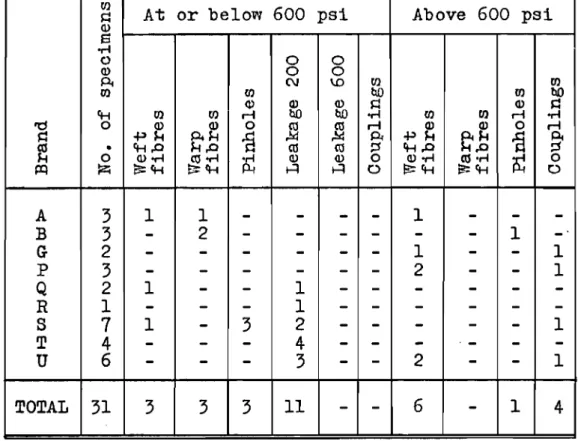
-TABLE III
MODE OF SECONDARY FAILURE OF THOSE SPECIMENS FOR vVHICH THE PRESSURE TEST COULD BE CONTINUED
AFTER prョLセry FAILURE
U}
At or below 600 psi Above 600 psi
Q (l) S oM 0 0 0 Q) 0 0 Pi C\J \D U} U} (1) rn tID rn tID Q) Q) Q) Q Q) セ
ct-t (1) rn .-i tID tID oM rn rn .-i oM
"d 0 Q) Q) 0
セ セ r-l Q) Q) 0 r-l
セ セh
・セ
.g
Pi セh・セ
s
PIe
• ct-t.o eu co セ ct-t.o セ0 (l)oM co oM .,-1 Q) (l) 0 Q)oM eu·,-I
セ 0 セ l2< a=ct-t E;:ct-t J:Lt H H 0 セ」エMエ セ」エMエ 0 A 3 1 1
-
-
-
-
1-
-
-B 3-
2-
-
-
-
-
-
1 -G 2-
-
-
-
- -
1-
-
1 p 3-
-
-
-
-
-
2-
-
1 Q 2 1-
-
1-
-
-
-
-
-R 1-
-
-
1-
-
-
-
-
-S7
1-
3 2- -
-
-
-
1 T 4-
-
-
4- -
-
.-
-
-U 6-
-
-
3-
-
2-
-
1 TOTAL 31 3 3 3 11-
-
6-
1 4 TABLE IVMODE OF TERTIARY FAILURE OF THOSE HOSES FOR WHICH THE PRESSURE TEST COULD BE CONTINUED
AFTER SECOlillARY FAILURE
At or below Above 600 psi 600 psi rn rn rn セ tID (1) tID Q) セ Q) セ ct-tS U} oM U} r-l .,-1 'd 0·,-1 Q) .-i Q) 0 r-l Q 0 セh セ セh
il
PI セ • Q) ct-t.o ct-t.o セoPl (l).,-I 0 Q).,-I
セ 0
I=Q ZU) E5:ct-t 0 s:ct-t 0
Q 1
-
1-
-
-R 1 1-
-
-
-S 2-
2-
-
-T 4 4-
-
-
-U 3-
-
1 1 1 TOTAL 11 5 3 1 1 11.2 Cause of "Final" Failure of Hose
The manner in which each specimen first failed to comply with specification requirements in the pressure test
has been presented in Table II. Such defects as excessive
leakage do not bring the test to an end. Vllienever the first
failure was of such a nature as to permit it, the test was continued and a secondary and often a tertiary failure occurred, as given in Tables III and IV.
In nearly every case the final failure was rupture
or separation of couplings. By presenting again the mode of
final failure it will be possible to bring out information on the effectiveness of mildew-proofing as applied to these hose specimens.
As already mentioned, both specifications require that before the pressure test a portion of the sample submitted for testing be buried in soil of prescribed microbiological activity, in loops, so that a part of each specimen is
covered and part not. If the specimen ultimately ruptured,
it was generally possible to determine whether the point of
rupture lay in the buried part or in the remainder. The
final failure is tabulated in Tables V and VI according to where the rupture lay.
vVhere rupture occurred in the unburied part, the
mildew-proofing must have been adequate. Such ruptures, if
they occur below 600 psi, are evidence of inadequate strength. This deficiency can also cause ruptures in the buried part; for an accurate comparison of the frequency of mildew-proofing failures with strength failures, the latter should be doubled
at the expense of the former. This reasoning assumes strength
failures to be uniformly distributed, though the number of samples is such that the probability of chance variation
influencing the conclusions is not negligible. There were several
cases where it was uncertain whether the rupture occurred in the buried or the unburied part; these are shown in an
intermediate column in the tables.
Results show that failures below 600 psi are more often due to poor mildew-proofing than to inadequate strength
or poor coupling. To pass 600 psi all three conditions must
be met; once this level is passed, however, the most common
weak point has been the coupling. In most cases, the couplings,
all of them new, were carefully put on at the Division of
Building Research. It is thought that the currently standard
method of attaching couplings with a soft brass expander ring 7/8 in. by 0.04 in. is not strong enough for pressures much
in excess of 600 psi. If couplings were required to stand
higher pressures, some improvement of the method would become necessary, for instance, the use of a thicker expander ring
8
-TABLE V
MODE OF FINAL FAILURE OF LINED HOSE
Failure at or below 600 psi Failure above 600 psi Brand
In
*
Not in Coupling In Not in CouplingS.B. ? S.B. S.B. ? S.B.
part part part part
A 6
-
-
-
-
-
-
-B 5 1-
-
-
-
-
-c
5-
-
-
-
-
-
-D 6-
-
-
-
-
-
-E-
-
-
-
1-
2 -F 6-
-
-
-
-
-
-G-
-
-
-
3-
-
3 H-
-
-
-
1-
-
5 I 3 2-
-
-
-
-
-Subtotal 31 3-
-
5-
2 8 J-
-
-
1-
1-
1 K-
-
-
-
-
1-
2 L 1 2-
-
-
-
-
-M 2 1-
-
-
-
-
-Subtotal 3 3-
1-
2-
3 N 1-
1 1-
-
-
-0 1 4 1-
-
-
-
-Subtotal 2 4 2 1-
-
-
-TOTAL 36 10 2 2 5 2 2 11*
S.B. - Soil buried.TABLE VI
MODE OF FINAL FAILURE OF UNLINED HOSE TWO SPECIMENS PER TEST ARE SOIL BURIED:
Failure at or below 600 psi Failure above 600 psi Brand
In Not in Coupling In Not in Coupling
S.B. ? S.B. S.B. ? S.B.
part part part part
P 2
-
-
-
-
1 1 -Q-
1-
-
2 1-
-R 3 1-
-
-
-
-
-S-
4-
-
-
-
-
-T 4-
-
-
-
-
-
-U-
-
-
-
1 1-
2 TOTAL 9 6-
-
3 3 1 2TWO SPECIMENS PER TEST ARE NOT SOIL BURIED:
Failure at or below 600 psi Failure above 600 psi Brand
Hose Coupling Hose Coupling
p
-
-
4-Q 2
-
1 -R 3-
-
-S-
2-
1 T 3-
-
1 U-
-
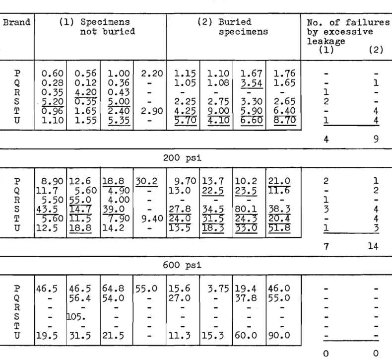
2 1 TOTAL 8 2 7 3 1.3 Leakage MeasurementsThe upper limits of acceptable leakage for unlined hose are:
3.4 m1/ft of length/min at 100 psi 14.2 m1/ft of length/min at 200 psi 142 m1/ft of length/min at 600 psi
10
-In
TableVII
the specimens have been put into two groups with summary columns showing the number of failures to meet the specification.From Table
VII,
it may be seen that soil burial appears to increase the leakage from an unlined hose.TABLE VII
LEAKAGE
(ml!ft!min)Brand (1) Specimens (2) Buried No. of failures
not buried specimens by excessive
leakage (1) (2) P 0.60 0.56 1.00 2.20 1.15 1.10 1.61 1.16
-
-Q 0.28 0.12 0.36-
1.05 1.08 3.54 1.65-
1 R 0.35 4.20 0.43-
-
-
-
-
1 -S ·5.20 D:)5 5.00-
2.25 2.15 3.30 2.65 2 -T5:9b
1.65 2.40 2.90 4.25 9.00 5.90 6.40-
4 U 1.10 1.55 5.35-
5.10
- -
4.100:00
- -
s:w
- -
1 4 4 9 200 psi P 8.90 12.6 18.8 30.2 9.10 13.1 10.2 21.0 2 1 Q 11.1 5.60 4":90-
13.0 22.5 23.5 II':1)-
2 R 5.50 55.0 4.00-
-
-
-
-
1 -S 43.5I4:f
39.0-
21.8 34.5 80.1 38.3 3 4T -,-;Do IT:"")
,-;gO
9.402""4:0 TI":""5
2"4":'")20:4
-
4u
12.5- -
18.8 14.2-
I'3":J I8:"3
- -
TI:O
)r:g 1 31 14 600 psi P 46.5 46.5" 64.8 55.0 15.6 3.15 19.4 46.0
-
-Q-
56.4 54.0-
21.0-
31.8 55.0-
-R-
-
-
-
-
-
-
-
-
-S-
nos.
-
-
-
-
-
-
-
-T-
-
-
-
-
-
-
-
-
-u
19.5 31.5 21.5-
11.3 15.3 60.0 90.0-
-0 0Note: The underlined leakage figures are those that exceed the acceptable.
1.4 セカゥウエL Rise Dnd Warp
The specifications do not impose limits upon twist,
rise or warp. In the case of twist, the direction if specified
as lithe twist shall be in a direction that would tend to tighten the couplings."
Table VIII presents the average results of all tests
for each brand. The lowest pressure at which rise or warp
occurred, and its extent, is also given. For example,
±
1 x300 means + I-in. warp at 300 psi. The correct direction of
twist is recorded as positive. TABLE VIII
-Revclutions of twist No. of
Brand
--
Rise Warp speo tmensPressure, psi showing
10 100 200 300 600 rise or warp A 0
-
-
+1 +1-
+lx300 2 B 0-
-
+1 +1-
-
+11/2x600 1 C 0-
-
+1/2-
-
-
-D 0-
-
+1 1/8-
-
-
-E 0-
-
+1 +1-
-
+lx600 2 F 0-
-
-
-
-
-
-G 0-
-
+1 1/8 +1 1/2 +lx600-
+lx600 2 H 0-
-
+1 +1 1/4 +lx300 +lx300 4 I 0-
-
+7/8-
-
-
-J 0-
-
+1 3/4 +2 1/2-
-
-K 0-
-
+1 1/4 +1 3/4 +lx600 +lx300 3 L 0-
-
+1 1/2 +2 +lx300 +2x300 3 M 0-
-
+1 1/2-
-
-
-N 0-
-
0-
-
-
-0 0-
-
+1-
-
-
-p 0 +3/8 +3/4 +7/8 +1 1/8-
+lx600 7 -Q 0 0 -1/8 -1/4 -1/2-
-
-R 0 +1/4 +3/4 +7/8-
-
-
+lx200 1 S 0 0 0 0-
-
-
-T 0 +3/8 +3/4 +7/8-
-
+lx300 3u
0 +1/2 +3/4 +7/8 +1 1/8 +lx600-
+lx600 712
-1.5 Elongation
The limits of acceptable change of length with pressure are:
Unlined hose -
5
per cent shrinkage betweena
and 10 psi10 per cent elongation between 10 and 300 psi.
Lined hose
a
per cent shrinkage betweena
and 10 psi15 per cent elongation between 10 and 300 psi.
TABLE IX
%
Elongation (*) BrandPre s stire , psi
a
to 10 10 to 100 10 to 200 10 to 300 10 to 600 A +1 +5 (+1) Ba
+6 (+10) C +1 (+1) -D +1 No +1 -E +2 +6 +8 Fa
measurement (+3) -G +1 +9 +13 H +1 for these +8 +16 I +1 +8 (+10) brands. J +1 +1 +11 K +1 +5 +9 L +2 +5 (+6 ) M 0 (+5) -N +1 +11-a
+1 +3 -p -2 +3 +5 +7 +11 Q +1 +2 +2 +4 +5 R -1 -1 -1 (-2) -S 0 +2 +3 +4 (+4) T (-2) +2 +3 +5 (+11) U -1 +3 +5 +6 +9*
Figures shown in brackets are the results of only one or two specimens reaching the appropriate pressure.Time Change of Length
Some of the unlined specimens showed a small change in length with time, during those parts of the pressure
schedule in which a constant pressure was maintained. TABLE X
At pressure, psi 100 200 600
after time in min
10 25 10 10 Brand Elongation
%
P 0 0 +1 +1 Q (-1) (-1) +1 +1 R-
-
-
-S 0 0 (+1) -T (-1) 0 (+1) -U 0 0 +1 +1Note: Figures shown in brackets are the results
of only one or two specimens reaching the appropriate pressure.
SECTION 2. HOSE CONSTRUCTION
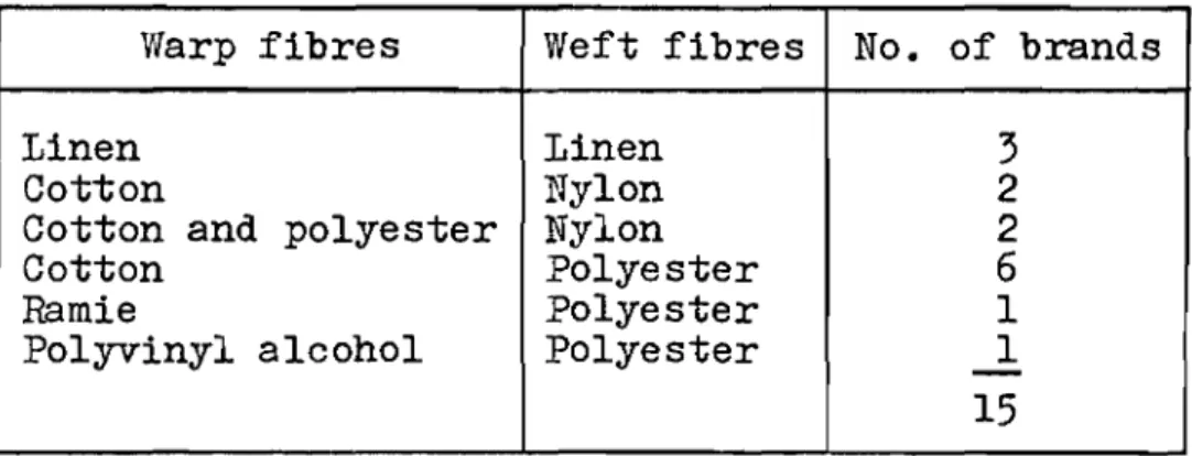
2.1 Jacket Materials Used
The unlined hoses all had linen warp and weft. The
lined and plastic-coated hoses were woven from the following fibres:
TABLE XI
Warp fibres Weft fibres No. of brands
Linen Linen 3
Cotton Nylon 2
Cotton and polyester Nylon 2
Cotton Polyester 6
Ramie Polyester 1
Polyvinyl alcohol Polyester
-
114
-The specifications have the following stipulations regarding the construction of hose:
"The hose shall be woven from first quality yards suitable for the purpose, which shall be practically free from
knots, shives and other imperfections. The fabric shall be
of uniformly even and firm texture and shall be free from all
defects that might affect its serviceability•••• The warp
yarns shall lie in a direction parallel to the length of the hose and shall cover the weft yarns sufficiently to protect
them from abrasion."
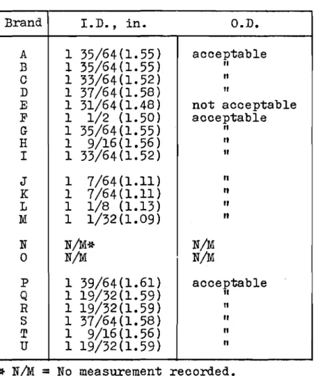
2.2 Diameter
The rate of flow for a given pressure should be regulated by any performance specification for fire hose. This has not been done directly in the specifications under review; they control it by regulating the inside diameter, surface roughness, and leakage, on which the rate of flow
must depend.* A limit on the outside diameter is also
necessary to ensure that the hose can be attached to a standard coupling.
The internal diameter of the hose, as received, is required to be not less than 1-33/64 (1.52) in. for lined
hose, or 1-17/32 (1.53) in. for unlined hose. The outside
diameter of either hose must be such that a standard coupling as specified in CSA Standard B89-1954, having a lip and bowl diameter of 1-11/16 (1.69) in., can be attached to the hose by the purchaser using regular equipment and expansion rings
1.500 + 0.003 in. in outside diameter.
To measure the internal diameter, a fresh cut is made across the hose, approximately 6 in. from the end of the
specimen. A tapered plug-gauge, with a taper of 3/8 in. per
ft and marked to indicate variations in diameter of 1/64 in.,
is then inserted until a close fit is obtained. The diameter,
as shown on the gauge, is then averaged with a second such measurement for each specimen.
*
Williams-Leir, G. Water flowswith forestry pumps and hose. Division of Building Research,
February 1960. 14p.
and pressures obtainable National Research Council, Internal Report No. 179.
TABLE XII
Brand I.D., in.
O.D.
A 1 35/64(1.55) acceptable B 1 35/64(1.55)
"
C 1 33/64(1.52)"
D 1 37/64(1.58) II E 1 31/64(1.48) not acceptable F 1 1/2 (1.50) acceptable G 1 35/64(1.55)"
H 1 9/16(1.56) ItI
1 33/64(1.52)"
J 1 7/64(1.11)"
K 1 7/64(1.11) It L 1 1/8 (1.13)"
M 1 1/32(1.09) It N N/M* N/M 0 N/M N/M p 1 39/64(1.61) acceptable Q 1 19/32(1.59)"
R 1 19/32(1.59) II S 1 37/64(1.58)"
T 1 9/16(1.56)"
U 1 19/32(1.59)"
* N/M=
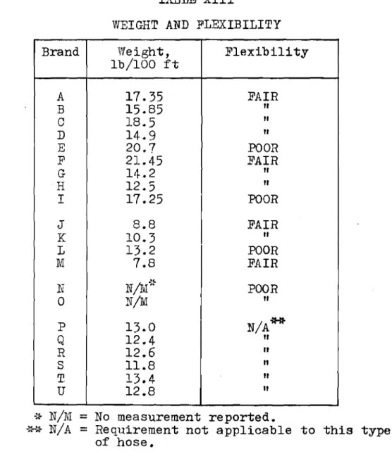
No measurement recorded. 2.3 Weight and FlexibilitySince this type of hose is intended for forestry purposes it is especially desirable that it should be as light as possible while satisfying the other requirements. The hose should also be capable of being handled with ease under all conditions. It is possible that hose acquired for forestry fighting purposes might be used in the winter for fire fighting-in buildings. Consequently, it has been thought fit to impose a requirement that the hose shall not be so
stiff at low temperatures that flexure would cause damage. The maximum acceptable weight for lined hose, when in equilibrium at 21 +l°C and 65 +2 per cent relative humidity, is 18.0 1b per 100 ft; exclusive of fittings. The maximum
acceptable weight for unlined hose, when dried to constant weight at 100-105°C, is 14.0 1b per 100 ft, exclusive of fittings.
16
-Each of the three 10-ft lengths of lined hose which has been leached and dried at room temperature, is to be
placed, tightly coiled, in a cold box at -18 ±2°C for 24 hours. Upon removal, the hose is to be rapidly uncoiled, and then
immediately recoiled in the reverse direction. This is done
before soil burial and the pressure test so that any damage
resulting from cold flexure will influence the result. An
assessment of the fleXibility of the hose was made and is shown as "FAIR" or "POOR" in Table XIII; no specimen was rated better than "FAIR".
TABLE XIII
WEIGHT AND FLEXIBILITY
Brand Weight, Flexibility
Ib/IOO ft A 17.35 FAIR B 15.85
"
C 18.5"
D 14.9"
E 20.7 POOR F 21.45 FAIR G 14.2"
H 12.5"
I 17.25 POOR J 8.8 FAIR K 10.3"
L 13.2 POOR M 7.8 FAIR NGセ N N/M" POOR 0N,IM
"
P 13.0 N/A*'* Q 12.4"
R 12.6"
s
11.8"
T. 13.4 It U 12.8"
*
N/M=
No measurement reported.セGBJ N/A = ReqUirement not applicable to this type
of hose.
2.4 Bonding of Lining
The following statements in quotation marks are from
CGSB Specification No. 13-GP-2; "3.2 The lining shall adhere
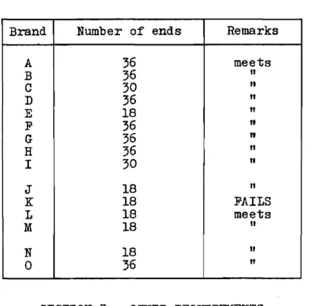
to the jacket over the entire surface." Any visible separation of the liner from the jacket is to be considered a failure. "6.9 Examination for bッョ、ゥョセ of Lining. Hose that has been subjected to leaching, coldlexing, soil burial, the pressure test and the heat resistance test shall be cut into lengths of at least 6 inches and examined visually for bonding of the
lining, while being flexed manually. Twelve ends taken equally from all the original lengths shall be examined. Not more than one defect shall be permitted where a single separation showing on the two ends resulting from one cut is defined as one defect. Pieces cut from the hose in the area where the hot block was placed shall be discarded.'I
TABLE XIV
Brand Number of ends Remarks
A 36 meets B 36
"
C 30 It D 36"
E 18"
F 36 It G 36 n H 36"
I 30"
J 18"
K 18 FAILS L 18 meets M 18"
N 18"
0 36"
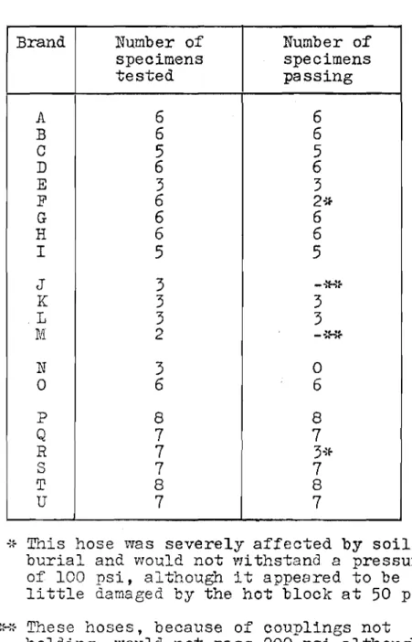
SECTION 3. OTHER REQUIREMENTS 3.1 Heat Resistance
After the pressure test, the hose is subjected to a heat resistance test. A block of steel 12 by 3 by 3 in. is to be heated to 260 +5°0 throughout for lined hose, and 400 +5°C for unlined hose, and then placed transversely on a portion of the specimen. Water is to be pumped through at 1 gal per min and a pressure of 50 +10 psi maintained. After 2 min +10 sec the block is removen, the flow stopped and the pressure raised, at 100 psi per min to 300 psi and held for 5 min. One specimen from each of the 10-ft lengths is tested. No specimens of any sample should fail at 300 psi.
18
-There is at present no specification for the
plastic-coated type hose. In this series of tests, therefore, the
plastic-coated hose was treated as a lined hose, and was
tested to the 260 セUᄚc temperature requirement.
TABLE XV
Brand Number of Number of
specimens specimens tested passing A 6 6 B 6 6
c
5 5 D 6 6 E 3 3 F 6 2* G 6 6 H 6 6 I 5 5 J 3 MセAッ K 3 3 .L 3 3 M 2 MBaセ .'" .'" N 3 0 0 6 6 P 8 8 Q 7 7 R 7 3.,1-S 7 7 T 8 8 U 7 7セaᄋ This hose was severely affected by soil
burial and would not withstand a pressure of 100 psi, although it appeared to be little damaged by the hot block at 50 psi •
NLhセ These hoses, because of couplings not
holding, would not pass 200 psi although they appeared to be little damaged by the hot block at 50 psi.
3.2
Aging of Hose LiningAccelerated aging of ャゥョゥョセN The lining is required
to pass an accelerated aging test, キセゥ」ィ in the case of natural
Brand Thiclmess I
Tensile strength Per cent elongation !Remarks
Unaged Aged Unaged Aged Unaged Aged
A .028 to .046 .031 to .039 530 to 1540 65 to 765 650 to 740 110 to 800 .036 .035 1095 330 700 425 fails .010 to .011 .010 to .011 1905 to 2875 1525 to 2325 780 to 900 810 to 910 B .010 .011 2370 1735 830 870 meets .022 to .047 .022 to .041 1280 to 1540 1230 to 1550 200 to 310 210 to 290
c
.029 .028 1430 1420 250 250 fails .029 to .031 .025 to .031 2055 to 3125 1450 to 2230 670 to 730 620 to 720 D .030 .029 2480 1870 700 650 meets .012 to .013 .012 to .013 1825 to 2305 1595 to 1935 840 to 880 880 to 950 E .013 .013 2045 1795 860 910 meets .033 to .051 .038 to .049 1210 to 1335 1135 to 1290 440 to 490 350 to 400 F .041 .045 1230 1195 465 370 failsG Lining too thin to be tested
.026 to .035 .030 to .037 1130 to 1960 915 to 1290 740 to 830 650 to 800
H .030 .033 1520 1020 790 735 fails
.029 to .034 .030 to .034 1000 to 1140 775 to 1420 710 to 760 650 to 780
I .031 .032 1080 1190 735 720 fails
J Lining too thin to be tested
.0105 - .0105 to .010 1980 to 2170 1905 to 2160 860 to 870 870 to 880 K .0105 .010 2080 2020 870 880 meets .038 to .046 .042 to .051 1345 to 1800 70 to 140 150 to 800 150 to 450 L .042 .046 1645 95 785 295 fails .022 to .029 .022 to .029 2705 to 3740 1960 to 2700 700 to 730 620 to 650 M .025 .025 3090 2320 710 640 meets
Note: The first row of figures is the range of figures reported for one brand; the second row
is the average of the figures reported for that brand.
I-'
20
-paragraph 4.8.1, provided the lining thickness is adequate for this test.
"4.8.1 After air-oven aging, the tensile strength
and ultimate elongation of natural rubber lining from unleached hose shall be not less than 60 per cent of the strength and
elongation of unaged specimens. The tensile strength and
ultimate elongation of unaged lining shall be not less than 1800 psi and 700 per cent respectively."
"6.10 Accelerated aging of lining. Specimens of
natural rubber lining, taken from the specimen supplied without couplings, shall be oven-aged in accordance with ASTM Method D573 at 80 +loC for 96 hours and tested for
tensile strength and elongation by asョセ Method D412 using
、ゥセ C.tt
3.3 Acidity
Method of test. Approximately
5
gm of yarn ravelledfrom the hose was boiled for 1 hr, with 100 ml of distilled
water with a pH of not less than 6.0 and not greater than 7.5. The water extract was then cooled to room temperature and made up to 100 ml with distilled water, after which its pH value was determined by a glass electrode.
TABLE XVII
Brand Test 1 Test 2
A 5.4 5.9 B 7.6 8.6 C 6.7 7.4 D 6.3 7.0 E 7.6
-F 7.2 7.7 G 5.9 6.3 H 6.6 6.7 I 6.5 6.6 J 6.8 -K 8.3 -L 6.0 -M 7.1 -N 6.3 -0 7.8 8.0 P 5.3 7.5 Q 8.0 8.0 R 5.4 5.3 S 7.2 7.2 T 8.6 8.5 U 5.7 5.6 1SECTION
4.
sャtィiセセryThe results given for unlined hose are summarized in Tables XVIII and XIX, and for lined hose in Tables XX and XXI0
Specification l3-GP-lb,
Ii"
Unlined HoseFor each test
5
specimens are required, one of whichis used for the tests on hose construction (Section 2) and
acidity (Section 3). For this program of work, there were
generally nine specimens available, two which were used for the tests on hose construction and acidity, and four which
comprised the "first test." The remainder were used for a
partial "second test.It Whatever the results of testing a
fourth specimen might be, they could not cause a group to pass the second test, if the other three specimens did not
pass. Thus the possible results are: 1 meets, 1 uncertain;
1 meets, 1 fails; and 2 fail. For two brands only, ten
specimens were available, and for these, "2 meet" is another possibility.
Specification l3-GP-2,
Ii"
Lined HoseIn each test four specimens are required. For some
brands only seven specimens were available so that the remarks in the preceding paragraph again apply; for one brand, only four were available so that only one test was done.
Hose Types Not Covered by the Specifications
For this series of tests, the types of hose (1 in.
lined and ャセ in., Rセ in. plastic-coated) were tested against
Specification l3-GP-2, in so far as it was applicable. CONCLUSION
No single hose met all the requirements of the
current specifications. However, each requirement was met
by more than one hose. None of the hoses tested had been
manufactured with these particular specifications in view, since the specimens were procured before the specifications
were promulgated. It is reasonable to expect that more than
one manufacturer will be able to produce hose to meet the new specifications.
...i.
TABLE XVIII
UNLINED ャセMinN HOSE SPECIMENS MEETInG REQUIREIIJIENTS
Brand
No.
of 4.1 4.2 4.4 4.5 4.6.1 4.6.2 4.7 4.7 4.11specimens Weight Dia. Elong. Twist Leakage Leakage Leakage Rupture H. R.
tested (a) 100 200 600 p 2 + 8 2 2 8 8 8 5 6(2N) 6 8 Q 2 + 7 2 2 7 0 6 5 4
(3N)
4 7 R 2 + 7 2 2 (b) 3 2 (4N)·:to 2(4N)0(4N)
0 3(4N) S 2 + 7 2 2 7 5 5 0 0(7N) 1 7 T 2 + 8 2 2 8 8 4 4 0(8N) 0 8 U 2 + 7 2 2 7 7 2 3 7 7 7 NNotes:
*
N indicates the number of specimens to which a test could not be applied because Nof failure at an earlier stage of the pressure schedule. (a) For columns 4.1 and 4.2, only two specimens were required.
(b) All elongation measurements above 10 psi were negative (specification has no allowance for such a case).
...
ill{LINED ャセMinN HOSE GROUPS MEETING REQUIRm,illNTS
Brand 4.1 4.2 4.4
4.5
4.6.1 4.6.2 4.7 4.7 4.11Weight Dia. Elong. Twist Leakage Leakage Leakage Rupture H. R.
100 200 600
P
zn"
2M 2M .'{, 2M 2M 1M IF 1M lU 1M IF 2MQ 2M 2M 1M lU" 2J.;' ill IF" 2F 2U ll!' lU 1M lU
R 2M 2M 2U(a) lM"lU IF IN.... IF IN 2N 2F 2N
S 2M 21'1'1 HllU IF"'" lU 2F 2F 2N 2F 1M lU
T 2M 2M 2M 2M 2F 2F 2N 2F 2M
U 2M 2M 1M lU 1M lU 2F 2F 1M lU 1M lU 1M lU
Notes:
*
1'.1=
meets; U=
uncertain, i.e., a set of four specimens was notcompleted, but those that were tested complied: F = fails.
N indicates that a set of tests on four specimens was not complete, since at least one of the four failed at an earlier stage of the pressure schedule.
(a) All elongation measurements above 10 psi are negative, a case which is not covered by the specification •
ro
TABLE XX
LINED ャセMinN HOSE spectiセens MEETING requiセjents
Brand No. of 3.2 4.1 4.2 4.4 4.5 4.1 4.1 4.1 4.8 4.9
specimens LLndng Weight Dia. Elong. Twist Wet Coupling Rupture ILR. Lining
tested (e) bonding patches aging
A 2 + 6 6 2 2 6 6 0(2N) 0(6N) 0 6 0 B 2 + 6 6 2 2 6 6
0(3N)
0(6N) 0 6 2 C 2 + 5 5 0 2 2(3N) 5 0(4N)0(5N)
0 4(lN) 2 D 2 + 6 6 2 2 6 60(4N)
0(611) 0 6 2 E 1 + 3 3 0 0 3 3 3 3 3 3 1 F 2 + 6 6 0 0 1(5N) 6 0(6N) 0(6N) 0 3(3N) 0 G 2 + 6 6 2 2 6 6 4 6 6 6 (c) H 2 + 6 6 2 2 6 6 6 6 6 6 0 I 2 + 5 5 2 2 5 5 0(5N) 0(2N) 0 5 0 J 1 + 3 3 (b) (b) 3 3 2 2 20(3N)
(c) K 1 + 3 1 (b) (b) 3 3 3 3 3 3 1 L 1 + 3 3 (b) (b) 3 3 0(311)0(3N)
0 3 0 1\1 1 + 3 3 (b) (b) 1(2N) 3 0(2N)0(3N)
0 1(2N) 1 N 1 + 3 3 (b) (b) 3 3 0(3N) 0(2N) 0 0 (d) 0 2 + 6 6 (b) (b) 6 6 0(5N) 0(6N) 0 6 (d)(a) N indicates the number of specimens to which a test could not be applied because of failure at an earlier stage of the pressure schedule. .
(b) Specification does not apply to this size or type of hose.
(c) Lining too thin to be tested; refer to Section 3.2 of this report. (d) No measurement made.
(e) For columns 4.1, 4.2, 4.9, only two specimens were required, except as noted for particular brands.
I\) -r-...
セ
LINED ャセMinN HOSE GROUPS MEETING requiセセents
Brand 3.2 4.1 4.2 4.4 4.5 4.7 4.7 4.7 4.8 4.9
Lining Weight Dia. Elong. Twist Wet Coupling Rupture H. R. Lining
bonding patches aging
A 2M 2M 2M 2M 2M 2F 2N 2F 2M 2F B 2M 2M 2M 2M 2M IF IN 2N 2F 2M 2M C 1M IV 2F 2M 2N 1M lU IF IN 2N 2F 1M IN 2M D 2M 2M 2M 2M 2M 2F 2N 2F 2M 2M E 1M IF IF 1M Ul 1M 1M 1M 1M 1M F 2M 2F 2F 2N 2M 21'1 21'1 2F 2N 2F G 2M 2M 2M: 2M 2M: 1M IF 2M 2M 2fiI (c) H 2M 2M 2M 2M 2M 2M 2M 2M 2M 2F I 1M lU 2M 2M 1M lU 1M lU 21'1 IF IN 2F 1M lU 2F J 1M (b) (b) 1M 1M IF IF IF IN (c) K IF (b) (b) 1M 1M 1M 1M 1M 1M 1M L 1M (b) (b) 1M HI IN IN IF 1M IF M 11.1 (b) (b) IN 1M IN IN IF IN オNセ N 1M (b) (b) 11.1 HI IN In IF IF (d) 0 2M (b) (b) 2M 2M 2N 2N 2F 2M (d)
(a) M
=
meets, F=
fails, U=
uncertain, i.e. a· set of three specimens was notcompleted, but these that were tested complied. 1'1 indicates that a set of tests
on three specimens was not complete since at least one of the three £ailed at an earlier stage o£ the pressure schedule.
(b) Speci£ication does not apply to this type or size of hose.
(c) Lining too thin to be tested, refer to Section 3.2 of this report. (d) No measurement made.
I\)
26 -ACKITmfLEDG-MENTS
The information on jacket materials, diameter and
acidity is due to Mr. C. H. Bayley of the Division of Applied
Chemistry. The information on tensile strength, ultimate
elongation and aging of the rubber lining is condensed from