.^
HD28
.M414
no.
WORKING
PAPER
ALFRED
P.SLOAN
SCHOOL
OF
MANAGEMENT
A
Case-based
System
toSupport
Electronic
Circuit
Diagnosis
Thilo
Semmelbauer,
Anantaram
Balakrishnan,
and
Haruhiko
Asada
WP#
3497-92-MSA
October,
1992
MASSACHUSETTS
INSTITUTE
OF
TECHNOLOGY
50
MEMORIAL
DRIVE
CAMBRIDGE,
MASSACHUSETTS
02139
A
Case-based
System
toSupport
Electronic
Circuit
Diagnosis
Thilo
Semmelbauer,
Anantaram
Balakrishnan,
and
Haruhiko
Asada
WP#
3497-92-MSA
October, 1992
A
Case-based
System
to
Support
Electronic
Circuit
Diagnosis
^7/7/70
Semmelbauer
LeadersforManufacturing M. I. T., Cambridge,
MA
Anantaram
Balakrishnan
Sloan Scfiool of
Management
M. I.T., Cambridge,
MA
Haruhiko
Asada
Department of Mechanical Engineering M. I. T.,
Cambndge,
MA
Abstract
Diagnosis
and
repairoperationshave traditionally beenmajor
bottlenecksin electronicscircuit
assembly
operations because they arelabor intensive and highly vanable.Rapid
technological advances, shrinking product lifecycles, and increasingcompetition inthe
electronics industry have
made
quickand
efficientdiagnosis critical forcostcontroland qualityimprovement,
while simultaneously increasing the difficulty ofthe diagnosis task.This paperdescribes acase-baseddiagnosis support system to
improve
the effectivenessand
efficiencyofcircuitdiagnosis by automatically updatingthe setof candidatedefects,and
prioritizingtestsduring thesequential testing process.The
case-basedsystem
storesindividual diagnostic instancesratherthan generalrulesand algorithmic procedures; its
knowledge
basegrows
asnew
faults aredetectedand
diagnosedby
theanalyzers.The
system
providesdistributed access to multiple users,and
incorporates on-line updating features thatmake
itquick toadapt tochanging circumstances.Because
itis easy to install,update,
and
integrate withexisting systems, thismethod
is well-suitedfor realmanufacturingapplications.
We
haveimplemented
a prototype version,and
tested theapproach
in anactual electronicsassembly
environment.We
describethe system's underlyingprinciples, discussmethods
toimprove
diagnostic effectivenessthroughprincipledtest selection
and
sequencing,and
discuss managerial implicationsfor successful implementation.1.
Introduction
1.1
Overview
Electronic circuitdiagnosis is theprocess ofidentifying the
component(s)
thatisresponsible for the malfunction ofacircuitboard so thatcorrective (repair)actioncan be taken.
Subsequent
exploration ofthe problem's rootcauses motivates processand
productimprovement
efforts.The
diagnosisand
repairloophas traditionallybeen
amajor
bottleneckincircuit board assembly. Recenttrends inthe electronics industry such as the
rapid technological advances,increasing product complexity,
and
shon
product lifecycles,have considerably increasedthe
imponance
ofquickand
efficient diagnosis, whilesimultaneouslyincreasing the difficultyofthe diagnosis task.
Reducing
diagnosistimeand
variability,
and improving
diagnosisaccuracybecomes
critical as electronicscompanies
strive towards lean manufacturing, quickresponse,
and
greater flexibility.This paperdescribes acase-based diagnosissupport system that
we
developed
inconsultation with a
high-volume
consumer
electronicsassembly
plant.The
plant, faced witharapid turnoverofproductsand
an increasingshonage
ofskilledtechnicians,wanted
a
means
toimprove
the efficiencyand
effectivenessofcircuitdiagnosis, reduce theworkload
on
itsfew
expert analyzers,and
develop a tool to trainnew
technicians, withoutdevoting significant
system development
resources.An
informal survey ofavailable systemsand
current practice revealed that, althoughthe literaturedescribes severalrule-based
and model-based
systems to supportdiagnosis, these systemswere
not widely used by theelectronics industry partlybecause they require considerable timeand
specialexpertise toinstall (e.g., for
knowledge
acquisition)and
update.The
case-based approachproposed
in this paperoffers apractical solution to thediagnosis support needsof industry.Itaccumulates
knowledge
on-line asanalyzers detectand
diagnosenew
faults.Using
thisinformation about priordiagnostic instances, the systemeliminates candidate defectsduring
thesequential testing process,
and
prioritizes subsequenttests.We
have
implemented
aprototype versionofthe system,
and
testeditin anactual electronicsassembly
environment
We
describe the system's underlying principles,outlinemethods
toimprove
diagnostic effectiveness
by
reducing thenumber
ottestsneeded
tocomplete
the diagnosis,and
discussimplementationaspects.1.2
Why
is circuitdiagnosis important?
Rapid changes
inelectronics productand
process technology, such as smaller,surface-mounted
components,
higherboarddensities, andmore
complex
circuitry,have
made
circuitdiagnosis
more
challenging.With fewer
accessibleconnectionsand
testpads, in-line functional testing can only identify theapproximate area orblock ofcomponents on
theboardthat isresponsible for the malfunction. Detaileddiagnosis
must
bedone
off-linethroughextensive probing
and measurement.
Each
component
and
connection on a circuitboard isa potential defect site,and
everysitecan
have
severalpossible defects such asanopen
or shortcircuit(due topoorsoldering orcomponent
misalignment),component
malfunction, inherentflaw inthe circuit design,placement
ofthewrong
component,
or defect in the board'sinternal wiring.The
failure rate ofa board containing hundreds ofcomponents
is, therefore, severalordersofmagnitude
higher than theprobability ofa singledefectivecomponent
or operation,making
testing
and
diagnosis inevitableeven
with highly capable placementand
solderingoperations. Isolating the rootcausein such
complex and
densecircuitsis arduousand
timeconsuming.
Annual
expensesdirectly related todiagnosisand
repaircanexceed
severalhundreds
ofthousands ofdollarseven
in amedium-sized
facility.Work
inprocess atthediagnosis stage
and
delayed feedbackforprocess control further increase this cost.More
importandy, the time
and
effortrequiredtodiagnose a faultyboard is highly variable(from afew
minutes toover4
hours)depending
on
the type ofdefect, the analyzer'sskill, theeffectivenessofdiagnostic tools,
and
the incentiveand performance
evaluation systems.Consequendy,
testing, faultdiagnosisand
repairoperations areoftenmajor
bottlenecks inmedium
or highvolume
printedcircuit boardassembly
facilities.The
costand
effort to train techniciansis alsobecoming
a significant concernforelectronics companies.
A
new
technician requires severalmonths
oftrainingand
experience with a particularboard to understand thecircuit'scause-effect behavior
and
thepotential rootcausesin itsmanufacturing process.
As
productlifecycles shrink, thetraining costs
must
beamortizedoversmallervolumes
foreach board. Diagnosisbottlenecksareespecially acute during thecritical production
ramp-up
period following anew
productintroduction. Capturing marketshare earlyis essential forcompetitive survivalin the electronics industry, butproduction facilitiesoften cannot achieve thenecessaryrapid
ramp-up
because yields are low,and
analyzers are least productive since theyhave
nothad
significantexperience with thenew
product.Fast
and
accuratediagnosis notonly reducesdirectmanufacturingcostand
flow time, butisalsoan essentialprerequisite forsuccessful qualityimprovement
efforts tiiroughimproved
product design (e.g.,Soederberg
[1992]), better process understandingand
characterization, tighterprocesscontrol,
and
close supplierpannership (e.g.,Wenstrup
[1991]).
The
ability toprovidequick information feedbackfrom
the diagnosis stage toprevious stages (includingvendors) is particularly important in
medium
and
highvolume
environments.
For
instance, a snick glue pin oraworn
placement
head, ifnotdetected1.3
Computer
support
for circuitdiagnosis
Manual
diagnosisofcircuit boards can be both inefficientand
error-prone. Empirical evidence(Rouse and
Morris [1985],Rouse and Hunt
[1986]) suggests thathumans
are not optimaJ diagnosticians since theyhave
difficulty ineffectively utilizing all the available testdata toprune the listof candidate defects
and
systematically selectthe testsequence.On
theother hand, building acompletely
automated
system that iscapable ofanticipating and diagnosing all possibledefectscan be prohibitively expensive; sucha systemmight
also require extensive timeand
effortby specialists (design and process engineersor software experts) toinstalland
maintain. Therefore, a system that assists, ratherthan replaces,human
diagnosticians ismore
practicable.To
cope
with thedynamic
electronicsenvironment, the
system
must
berobustand
flexible, i.e., it shouldeasily adapt todesignand
process changes. Practitionersprefera flexiblesystem
that possiblydiagnoses onlythe
most
common
defect types (thataccountfor avastmajorityofboard failures) toone
that offerscomprehensive
diagnostic coveragebutcannot easily adapttochanges.The
case-basedapproach offers the potential tomeet
these requirements. Unlike otherknowledge-based
systems, the case-based system accumulatesknowledge
on-lineby
storingdiagnostic instances (asanalyzers identify
and
diagnosenew
faults)ratherthan generalrulesoralgorithmic procedures.Each
diagnostic instanceorcasecorrespondsto a distinctdefect; itis representedby
the setoftestsconductedand
theirobservedoutcomes
for that defect.
By
comparing
the testresults for the currentboard with previous instances,the
system
can eliminatecandidatedefectsand
determine the effectivenessof subsequenttests.
Recording
diagnostic instances rather than general rules has the p)otentialdisadvantageof requiring a large database.
However,
our prototype implementation experience suggests that thevastmajority offaultsencountered in practicecorrespond toavery small fractionofthe setofall possible instances.
Because
ofits simplicity, the system can be maintainedby
the analyzers themselves, avoiding long knowledge-acquisition delaysand
the consequentsystem obsolescence. Furthermore, thestandardformat ofacasepromotes
learningand
information sharingamong
technicians (fromdifferent shiftsor productionlines),and
enables the systemtoserve also as a trainingtool for
new
technicians.These
featuresmake
the case-basedsystem
viableand
usefulfor real manufacturing applications.Although
case-basedreasoning has
been
appliedtootherdomains
such as legalargument and customer
service,we
arenotaware
ofits previousappHcation to electroniccircuitdiagnosis.We
enhance
thebasiccase-based approachtoincorporate historical data
and
other priorinformation forsystematically selectingtests
and
optimizingthe search process.To
validate the overall approach,we
implemented and
testeda prototype versionofthe system in ahigh-volume
printedcircuit board (surface-mount)
assembly
line producinga hybrid (analog-Kiigital) circuit board for a state-of-the-artconsumer
electronics product.Our
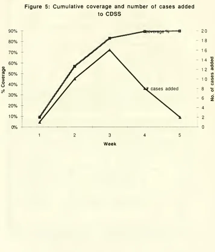
implementationpermitsdistributedusage via a local access network. Within five
weeks
of installation,thesystem
achieved90%
coverage, i.e., the system had acquiredenough
diagnostic instancestocorrectlydiagnose
90%
ofthedefects occuring in the fifth week.Based on
our implementationexpenence,
we
offersuggestions toimprove
themanagement
ofthediagnosis function; in particular,
we
propose a proactivemanagement
approach and incentiveschemes
thatemphasize
the analyzer's processimprovement
rather thanfault-findingrole.
The
restofthis paperisorganized as follows. Section 2 describes the circuitdiagnosis process inmore
detail,and
develops thegoals foran idealdiagnosissuppon
system. Section 3 discusses the underlyingstructureand
operation ofa basiccase-basedsystem
forverifying defects based
on
testoutcomes. Section4
presents systemenhancements
tooptimizetest selection usinghistorical dataand otherpriorinformation on the likelihoodof
different defects.
We
present adynamic
programming
formulationoftheoptimal testsequencing
problem
tominimize
theexpectednumber
oftestsper board, andoutlineheuristic
methods
foron-line testselection. Section 5 brieflydescnbes
ourprototype implementationand
the lessonswe
learnedfrom
this implementation exercise,and
identifies directions forfurtherwork.
2.
The
Diagnosis
Process
2.1 In-line
testing:
Capabilities
and
tradeoffs
Circuitboard
assembly
linestypically contain in-line inspectionand
testing stages, afterplacement
and
soldering operations (see, forinstance.Noble
[1989] for adescription oftheprocessing steps in printedcircuit board assembly).
The
main
purpose ofthese in-linescreening operationsis toidentifydefective boards,although they also
have
limited diagnosticcapabilities.For
instance,visualand X-ray
inspectioncan identify missingor misplacedcomponents and
possiblycertain solderdefects, but are not effectiveorreliable fordense boards with smallcomponents.
Furthermore,complete
manual
orX-ray inspectioncan
be very timeconsuming and
expensive.Two
typesofin-line electrical tests areavailable—
in-circuit testingand
functionaltesting. In-circuittestsverify the functionalityofindividual
components on
the boardusingautomated
testequipment
(see, for instance.Maunder
and
Tulloss [1990]).They
canisolate
and
precisely identifycertain typesofdefects (e.g.,open
or shortcircuits,defective passivecomponents),
but require hardfixturingand
programming
that is difficult to justify forshort production runs.Moreover,
the increasing useof surface-mount technologyand
the high costofboard"realestate"
make
in-circuit testing infeasibleorlimit theirdiagnosticcapabilities(Garcia-Rubio [1988]). In-circuit testsare alsoprone to
measurement
errors (see, forexample.
Chevalier [1992]) especiallyfor small, highperformance components.
leadingto false acceptanceor rejectionofboards. Functional tests
measure
the circuit'sresponse (atthe board's output
pons
oredge
connectors) todifferentcombinations ofinputsignals. Functional testscan confirm
whether
the interactionsbetween
variouscomponents
meet
the specifications; typically, they can trace aboard's failure to the responsible circuit,but not to aparticularcom]X)nentorconnection in this circuit.
Selecting the testing strategyfor aproduct involves addressingtradeoffs
between
higher
assembly
cycletimes (forall boards) toconductextensive in-linediagnostic testsversus higheroff-tinediagnosis effon (fordefective boards)
when
the in-line testsdo
nothave
highresolution.As
theboarddefect rate decreasesand
component
density increases, this tradeoffincreasinglyfavors the strategyofusingin-line testingonly to identifydefective boards; detaileddiagnosis
and
defectverification istiienperformed
off-line byskilledtechnicians.
We
next describethisoff-line diagnosis process,and
identifyopportunities tosupport this process usinga
computer-based
system. Forbrevity,we
willuse the
word
"diagnosis" to referto the detailed, off-line diagnosisprocedure after a board hasfailed in-line (functional) tests.2.2
Sequential
testing
procedure
for off-linediagnosis
Diagnosing
acircuitboardthat has failed functional testsentailsidentifying tiie source ofthe malfunction (e.g., acompxDnentorconnectionon
the board)so thatappropriate corrective action (e.g.,replacing or resoldering thecomponent)
can betaken torepair theboard
Diagnostic information also serves as the input forrootcause analysisand
continuous
improvement
of vendors, processes,and
product design.We
define a dfifg^las the finest grain source ofmalfunction thatcan beunambiguously
identified
by
the analyzer.Each
defect hasan associated corrective action; differentdefects
might
require thesame
correctiveaction. For instance, adefective resistorcanactaseithera shortcircuitoran
open
circuit. Ineachcase, thesymptoms
and
themeans
toidentify the
problem
are different; therefore,we
view
thesetwo
possibilitiesas separate defectseven though
bothrequirethesame
corrective action (namely, replacingtheresisitor).
Each
defect has asetofassociatedsymptoms
thatthe analyzermust
discoverby
applyingone
ormore
tests.A
testis an action thatmust
beperformed
eitherby
atechnician or
by automated
testequipment, resultingin an observation aboutthe behavior of the board.A
testmight
consistof applying a specified setofelectrical inputs, adjustingcertain circuitelements (e.g.,tuningcapacitors),
and
probing selectedlocationson
the circuit boardtomeasure
thevoltage orview
the electrical signalon
anoscilloscope.Each
test has
two
ormore
possible resultsoroutcomes
(e.g.. voltage is greater than 4.5 volts orless than 4.5 volts); observe thatif theoutputmeasurement
iscontinuous (e.g., voltage)we
discretize it by definingtherange of continuous values associated with each outcome. For convenience,and
without loss ofgenerality, allofour subsequent discussionsassume
thatevery test has
two
possibleoutcomes which
we
denote as or 1.The
outcome
ofa testdepends on
the defectin the board.We
permitdefects tohave indeterminateoutcomes
for certain tests, e.g., foracertain defect, the voltage at a particularlocation
may
beeitheror 1
depending
on, say, the state ofa tlip-flopdevice.We
also recognize thatthe analyzermight have
onlypartial priorinformation regardingwhich
defect produceswhat outcome
foreach test;
however,
we
assume
thatthe available information is adequate to uniquelyidentifyeachdefect.
To
identify the truedefect in a malfunctioning board, the analyzeruses a sequential testingprocedure
.The
process starts with a candidate set ofdefects(which
depends
on
the board'sfailuremode
during functionaltesting)and
a setoftests thatcan distinguishbetween
thesedefects.The
analyzersuccessively selectsand
applies varioustests,observes the
outcome
ateach stage,and
eliminates (fromthe candidatedefect set)alldefectsthatcannot
produce
theobserved outcomes. Ifthe initialcandidatedefect set iscomplete
(i.e.,the setcontains all possible defects),and
the setofavailabletests iscomprehensive
(i.e.,some
combination ofknown
testoutcomes
uniquely identifieseach candidatedefect), theprocedure terminateswith the truedefect as the only remainingmember
ofthecandidatedefect set.Inpractice, analyzers
might
notalways
followa systematic procedure to selecttestsand
eliminate defects. Diagnosis is oftenconsidered an "art",
and
analyzers rely largelyonintuition,
some
circuitknowledge,
memory,
and experience as theyperform
diagnosis. Often, theydo
notformally maintainand
update thesetof candidatedefectsby comparing
the defects' expected test
outcomes
with the observedoutcomes. Indeed, the setof candidatedefectsand
theirexpectedoutcomes
may
noteven bedocumented,
andmight
vary
from
technician totechnician.A
common
"myopic
"approach fortroubleshooting consistsofhypothesizing aparticular defect,attempting toverify it by performingthe
appropriate tests, revising theguess ifthe testsdisprove the first hypothesis,
and
soon.Alternatively, theanalyzer
might
follow apredeterminedtestsequencerepresented, forinstance, as afault tree.
A
purelymanual
diagnosis process can be both inefficient and inaccurate especiallywhen
itisnotsupportedby
clearprocedures and documentation. Forinstance, using a staticfault treecanresult in unnecessary tests and unproductive search (relativetoanapproach
that usesrecent defect history to guide the search). Likewise, diagnosis without adequatedocumentation
and
formal recordingprocedures canlead to replicationoftestsandfalseidentification. Also, these informal approachesare not
conducive
to learning,transfering
knowledge
toother analyzers, or generating appropriate information forqualityimprovement.
To
identifythedesirablecharacteristicsofacomputer-based system
toassist2.3
Diagnosis decision
support
requirements
Consider an intermediate stage in thediagnosis process
when
the analyzerhas applied severaltestsand
observed the resultsof each test.The
analyzernow
faces fourrelatedquestions,all
aimed
atdecidingwhat
todo
next:(1)
Given
theoutcomes
ofall previoustests, canwe
concludethat the boardcontainsa specific(known)
defect?(2)
Does
the boardcontain apreviouslyunknown
defect?(3) If
more
thanone (known)
defectremain ascandidates,which
available test(s)can distinguishbetween
these defects?(4)
What
testtoapply next?We
will refer to the firsttwo
questionsas Defect Identification,and
theremaining
two
as
Test
Selection.Consider
the information needs and actionsfor thedefect identificationquestions.An
affirmative
answer
toeitherquestion takes the boardout ofthe regulardiagnosisiteration.In the firstcase, the action consists of repairing the identified defect,possibly after
confirmingthe diagnosis. If
no
known
defectcauses theobserved
cumulative testoutcomes
(i.e.,theanswer
toquestion 2 is affirmative),we
have three possibilities: (i) theboardcontains a
new
defect,or(ii) theassumed
testoutcomes
fortheknown
defectsareinaccurate,or(iii) the actualtest
outcomes were measured
incorrectly. In all tiireesimations, the boardrequires extraordinary actions such asconfirming previous test
outcomes,
consulting with designand
process engineers, checking with suppliers,and
updatingcurrent
knowledge.
Ifmultiple
(known)
defectsremain
in thecandidate set, thetestselection questions firstseektoidentifyrelevant tests,not yetperformed, thatcandistinguish
between
theremaining
possibledefects. Conceptually, thisprocess corresponds to determining,foreachavailable test, ifthattesthasdifferentexpected
outcomes
for the candidatedefects. Ifno
suchtest is available,theanalyzermust
developand
applyone
ormore new
tests todistinguish thedefects. Otherwise,
we
must
decidewhich
among
the availableteststoperform
next.As we
shall see later, thisdecision impacts thenumber
ofiterationsneeded
to
complete
thediagnosis.Computer suppon
for the defect identification questionsmight
consistofa databaseorlogical reasoning system thatautomatically
compares
the observedtestoutcomes
with theexpected
outcomes
forall candidatedefects,and
eliminates defects with inconsistent outcomes. Similarly, to supporttestselection, acomputer-based system
can identify therelevanttestsateachstage,and apply a systematic
method
to select the nexttest.To
beinitializing
and
updating,and
quick response.We
listbelow
theseand
other desirable featuresofacomputer-based system
tosuppon
electronic circuitdiagnosis:•
Development
effort:Given
the short productlifecyclesofelectronic products,we
require asystem
thatbecomes
operational quickly and withoutsignificantexpense.•Maintainability/ robustness:
The
systemmust
be easyto update, preferably by the users themselves; relyingon
external resources to update the system (e.g., softwareexpens
and
knowledge
engineers) often introduces delays, causing inconsistenciesand
system obsolescence.Another
important requirement isthe system'sability to adaptgracefullytothe frequentdesign
and
processchanges
thatcharacterize theelectronics industry.• Compatibility: Techniciansoften
view
structured tools and methodologiesasimpediments
to creativity; compatibility with current practicesand
the cultureoftheorganization is, therefore, critical tothe success
and
effectivenessofthe system.System
ergonomics, easeofuse, flexibility,
and manual
ovemde
options aresome
of theways
toimprove
compatibility.•
Response
time/efficiency: Sinceeach
boardrequires severaltest iterations toprune thecandidate defect set, the
system must
respondrapidly tothesequestions so thatdiagnosisdoes
notbecome
thebotdeneck
activity.• Effectiveness:
The
main
purpose ofadiagnosis supportsystem
is toreduce thediagnosis time per board. Partofthissavingscomes
from
eliminating errorsand
automatingsome
oftheroutinebookkeeping and
lookup functions.Two
other features can reducediagnosistime:
• reducing the (expected)
number
oftests through systematic searchand
principledtestselection
and
sequencing; and,• providing
good
"coverage", i.e.,when
thesystem
has stabilized, itmust
correctlydiagnosea large percentageofthe defects.
Other
desirablesystem
featuresincludeabilities to: interface with existing databases, prepareperiodicsummary
reports for processimprovement,
highlight inconsistenciesand
faciUtate learning,diagnose bothdigital
and
analog (e.g., radiofrequency) circuits,and
operatein multi-userenvironments.
The
next section uses theseperformance
criteriatomotivate thecase-based
method.
3.
The
Case-based
Approach
for Circuit
Diagnosis
3.1
Knowledge
base
for
diagnostic
systems
Circuitdiagnosisrequires three broadclassesof
knowledge
—
historic, heuristic,and
fundamental
knowledge.
Historicand
otherpriorinformationon
the likelihoodofdefects can help theanalyzer prioritizecandidatedefects, thusenabling an effective choiceoftestanalyzer mightfirst
examine
thatpan
before pert'orming othertests. Heuristic orempiricalknowledge, sometimes
termed "shallow"knowledge,
refers to anempincal
associationbetween
observedsymptoms
and diagnostic conclusions. This categorymight
include rulesand
procedures,as well astricks orshoncuts thatthe analyzer hasfound
to be effectiveaftersome
troubleshootingexpenence.Fundamental
or"deep"knowledge
impliesan understanding ofthe underlying physicsofcircuitelements
which
we
use topredictcircuit response.
Design and
testengineersrelyon
such fundamentalknowledge,
often
encoded
ina circuit simulator, todesign and troubleshoot electronic circuits.Depending on
the primary sourceof diagnosticknowledge,
we
can distiguishbetween
experience-based (empirical
knowledge) and model-based
(fundamentalknowledge)
systemstosupportcircuitdiagnosis.
The
model-based
approach uses ananalyticalmodel
ora circuit simulatortodynamicallyidentify the potential causes forthe observedsymptoms
duringthe sequential testingprocess. Since diagnosisentails "backtracking"(i.e.,given ceruin
observed
symptoms
or outputs,what
valuesofcircuitelements canproduce
these outputs),we
need
a translator toconven
traditional circuitdesignmodels
(thatcharacterize the output foragivencircuitconfiguration) intocorrespondingdiagnostic models.
Davis and
Hamscher
[1988] illustrate the three basic steps—
hypothesisgeneration, hypothesistesting,
and
hypothesisdiscrimination—
inmodel-based
diagnosis. Gensereth [1984],deKleer
and Williams
[1987],and
Hamscher
[1988] describe variousmodel-based
systems todiagnosedigital circuits.The
most
common
experience -based approach
is arule-based (expen)system
that relieson
the experience ofhuman
expertstodevelop if-then rules thatenablethe systemto reason aboutthe behavioroftiie
malfunctioning board (see
Semmelbauer
[1992] for an illustration ofthis approach).One
ofthe pioneering apphcations ofthe rule-based
approach
was
for medical diagnosis (e.g.,see
Harmon
and King
[1985]). Unlike the fieldof medicine,however,
electroniccircuitsand
manufacturing processes vary widely,and
thetechnologiesundergo
frequentand radical changes. Ingeneral, the literatureon knowledge-based
diagnosticsystems focusseson
knowledge
representation issuesand
inferencemechanisms
to identify the underlying source oftheproblem,and does
not adequately addressissuesofoptimizing the sequential search process.For
electroniccircuitdiagnosis, both themodel-based and
rule-basedapproachesoffer certain advantages, but alsoimpose
limitations.By
consideringa decision suppxsrtframework
thatcombines
both approaches inacomplemetary
fashion,we
can exploittheirrespective strengths
and
overcome
the disadvantages.Model-based
systems offertheadvantage ofdirecdy integratingdesignand diagnosis:
when
the designerchanges
the circuitschematic (and addsrelevantsub-models
fornew
components), the diagnosismodel
is automatically updated, permitting instantaneous troubleshooting capability without
they arevery computationally intensive,
model-based
diagnostic systems are not well-suited foron-lineapplications. Furthermore, technicaldifficulties still remain in buildingsuitablediagnostic
models
for analogcircuits (see, forexample, Bennetts [1981], Kritz andSugaya
[1986],Tong
etal. [1989])due
to bi-directional signal propagation,and
the impact ofphysical layoutand
toleranceson
the performanceof high speed radio-frequencycircuits. Dealing with bridge defectsand
improper
(open) connections alsoposesproblems
since the basiccircuitstructure itself
changes
(PriestandWelham
[1990]).On
theotherhand, therule-based approach can incorporate heuristic
knowledge
to deal with these complexities,and
provide quickon-lineresponse during diagnosis; the infrastructure oftools to
implement
a rule-basedsystem isalso quite well-established.However,
traditionalexpert systems
might
require longdevelopment
times (Priestand
Welham
[1990]), especially for initialknowledge
acquisition (e.g.,Newstead
and
Pettipher [1986]). Furthermore, since eachcomponent
and connectionon
the board can cause malfunction, anticipatingand encoding
rules forevery possibledefectis almost impossible. For instance, the initialknowledge
thatwe
acquired forone
board tobuild aprototype system covered less than20%
ofall the defecttypes thatwere
encountered during the firstfiveweeks
ofsystem
operation. Finally, asystem
that relieson
software experts orknowledge
engineers to updatethe
knowledge
base (forinstance,when
the circuit designor manufacturing process changes) can introduceexpensive delays.To
cope
withthe rapidpace ofchange
inthe electronics industry,we
requireadiagnostic
system
thatcan both adapteasily tothe changing environment,and
reduce diagnosis time in productionby
providingquick on-line response. Next,we
describe a case-basedapproach
thatis similarto rule-basedsystems in itson-line operation, butcan exploit thecapabilities ofmodel-based
systemstoadapt tochanging circuitdesignsand
new
defects.3.2
Elements
of
case-based
reasoning
The
goalofourprojectwas
todevelopand
testa diagnostic support systemthatisviable inapracticalmanufacturing environment.
Two
importantobservations regarding practice motivated ourproposed
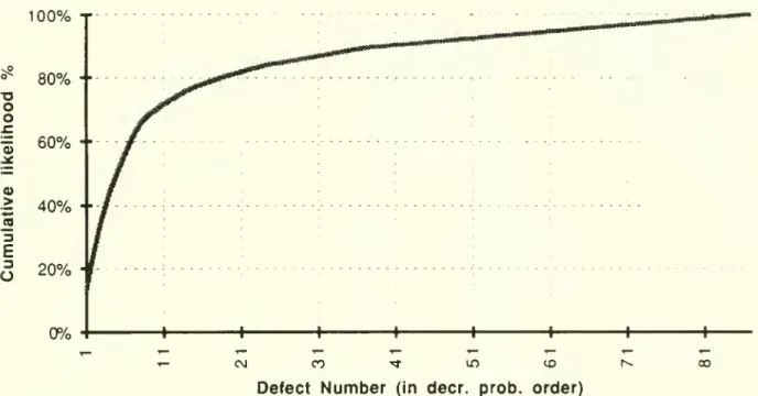
case-based approach:1.
The
ubiquitous80-20 law
applies also to electroniccircuitdiagnosis, i.e., less than20%
ofallpossible defectsoccur
in over80%
ofthe defective boards. Figure 1,which
shows
the cumulativerelative frequencies ofvarious defects (arrangedin decreasingorder of occurence)forour prototype system,clearly illustrates this
phenomenon.
Given
this80-20
characteristic, asystem
thatcanoperate with incompleteknowledge
, progressivelyaddingdefects asthey are encountered, is preferable toenumerating,apriori, all possible
defects. This strategyhas fourimportant advantages: (a) the developmentaleffort and timeislikely to besignificantly lower; (b)focusing
on
the relativelyfew
defectsthat haveoccured inthepastcan significantlyreduce theresponse time; (c) since it cantolerate
incomplete
knowledge and
can be updatedon-line, the system can easily adapttochanges
inprocess
and
productdesign;and
(d)by
relyingon
human
expens
todiagnosenew
defects, the systemis non-threatening and hence likely to be well-accepted.
Our
experience (reportedin Section 5)indicates that the strategyofprogressivelyadding
new
defects as they are encountered provides over
90%
coverage within justafew
weeks
of operation.2.
A
simpleway
to "learn"from
an expertanalyzer is by recordingthe actions—
the testsperformed
and
theirrespectiveoutcomes
—
as the analyzerexploresand
identifies anew
defect.The
observedoutcomes
forall the teststhat the analyzerapplied todiagnose theboardcharacterize the
new
defect,making
ita convenientknowledge
representation forsystem
maintainability,and
as ameans
tocommunicate
among
expens.Case-based
reasoning(CBR)
originated in the areaoflegalargument
(hence, the term"case").
An
early system,HYPO,
operated in thecommon
lawdomain
oftrade-secret law;the
system
combines
reasoning about the statutes (rules) with the precedents (cases) thatconcern them.
The
problem
offindingthe case(s) appropriate to the currentsituationamounts
toclever searching ofthe case baseon
anumber
ofsignificant attributes.The
"closest" cases withrespectto these attributes are selected forperusal
by
the researcher. Legalargument
continuestodominate
themost
recentcase-based reasoning literature (see, forexample,
Risslandand
Skalak [1988]). Applications ofCBR
tothe fault diagnosisare limited.Lee and
Liu [1988] applyCBR
to roboticassembly
cell diagnosis,and
Ishidaand
Tokumaru
[1990] present ageneralized approach tocase-based diagnosis using the frame theory.For
electroniccircuitdiagnosis, the case-based approachoffers the attractivefeaturesofcompatibility
and
incremental,on-hne
knowledge
acquisition; the system cantolerate incomplete
knowledge, and
its coverageincreases withtime.We
enhance
theconventional case-based approach
by
addingfeatures to incorporate:(i) robust
knowledge
acquisition: the systemidentifies incompleteand
inconsistentknowledge
(e.g.,due
tomeasurement
errors ordesign changes),and
incorporatesverification
and
updating steps tocorrect these errors;(ii)distributed usage:
by implementing
the system inadistributed client-serverenvironment
with a shareddatabase, several userscan simultaneously accessand
use thesystem; and,(iii)effectivetestsequencing: the system reduces the
number
oftestsby
applyingtestselection heuristics that accountfor priorprobabilitiesofdifferent defects.
In theelectronic circuitdiagnosis context, acase is an instance ofadiagnostic
experience, represented by itstestoutcomes.
(A
rule,by
contrast, is a generalization about diagnostic experience gathered overtime.)Each
casecorresponds toa particular defect.The
casebase
consistsofthecollection of instances correspondingto different defects observed inthe past. Recall thateachdefect haseithera deterministic or indeterminateoutcome
forevery test; funher, the valueofa deterministicoutcome
might
beknown
(0or1)or
unknown.
For
agiven defect,we
r. ^r toits setofexpectedoutcomes
for all testsas thesignature
of that defect.Suppose
we
have n
defect typesand
m
available tests.We
visualize the case base as a n xm
matrix, with eachrow
corresponding to a previouslydiagnosed
caseor defect.The
irow
in the case base represents the signature ofthe i defect type, i.e., thejelement
ofthisrow
has a 0, 1, 1, orU
depending
on whether
theexpected
outcome
oftestj fordefect iis 0, 1, indeterminate, orunknown.
We
permit theuserto
dynamically
add rows
(cases)and
columns
(tests) tothe case base asnew
defects aredetectedand
diagnosed (incrementalknowledge
acquisition).3.3
Diagnosing
a
defective
board:
Successive
refinement
through
case
matching
Diagnosing
adefective board correspondsto gatheringenough
information (byperforming
testsand
observing theiroutcomes)
about the board's signature, whilesimultaneously searchingthe case base, to identify a
matching
case. Ifno matching
case isfound, the boardcontains a
new
defector an inaccuratecase. In either situation, thecase basemust
beupdated toreflectthis latest experience.We
remark
that the general case-basedapproach goes beyond
casematching
and database updatingfunctions topossibly includereasoningand
extrapolation.Our
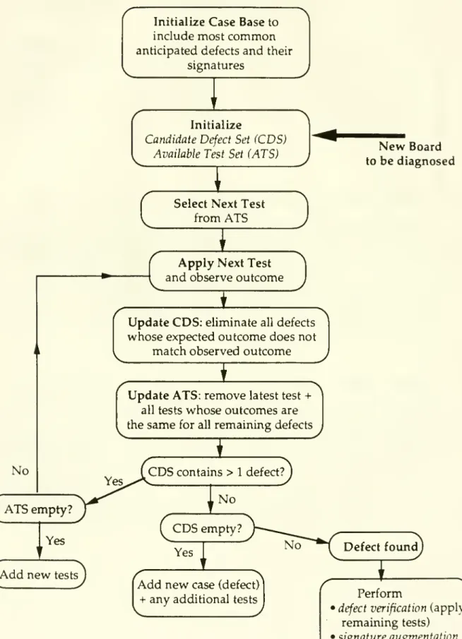
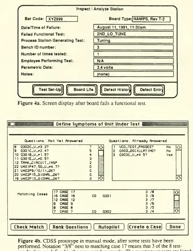
implementation doesnot exploit these additionalcapabilities. Figure 2
shows
thecomplete
flowchart forour case-basedcircuitdiagnosis supportsystem
(CDSS).
We
firstexplianhow
thesystem
operates beforedescribinghow
toupdate thecase base (Section3.4). Section
4
descnbes
enhancements
toimprove
thesystem'stest sequencing capabilities,
and
Section 5 discusseshow
tointegratethis system withamodel-based
approach.At
each stageofthe search process, thesystemmaintains: (i) a candidatedefectsetconsistingofall
known
defectswhose
signaturesmatch
theobservedoutcomes
for all the testsperformed
thusfar,and
(ii) theavailable testsetcontainingall tests that havenot yetbeen
perfonned
butwhose
outcome
differentiatesone
ormore
candidatedefectsfrom
theremaining
defects in thecandidate set. In the basic versionofthe case-basedsystem, theanalyzer
chooses
atestfrom
the availabletest set, performsthis test,and
observestheoutcome
ofthetest. (In Section4
we
describesystemenhancements
tooptimally select thenexttest).
When
theanalyzerenters the observedoutcome
into thesystem, thecandidatedefect set
and
available test set areupdated as follows:•
remove
from
thecandidatedefectsetalldefectswhose
expectedoutcome
for thelatest testdiffersfrom
theobserved outcome.
Note
thatwe
retain all defectswhose
outcome
• delete the testthat
was
justperformed from
the available test set; also,remove
any testwhose outcome
is thesame
(orunknown
or indeterminate) for all the remaining defectsin theupdatedcandidate defectset.
Ifthe initialcase base is
comprehensive
(i.e.,containsall possible defecttypes, and hasenough
information regarding expectedoutcomes
touniquely identify eachdefect)and
accurate, the process
must
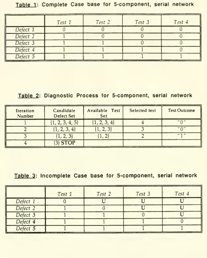
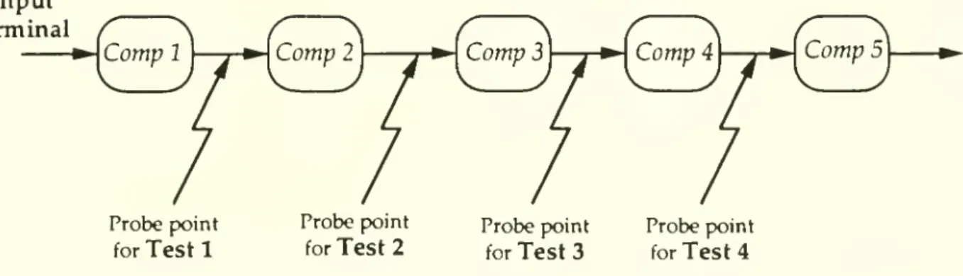
terminate with the candidate defectsetcontainingonly the true defect.To
illustrate this process, considerthe simple5-component,
seriesnetwork
shown
inFigure 3.
Suppose
we
have
a boardwhose
abnormal
outputsignal for the functional testindicatesmalfunction in
one
ofthe 5components
(all the intermediateconnectionson
theboard are good); fori
=
1,2 5,defect i refers to amalfunction incomponent
i.We
have
four availableteststhatapply a stimulusattheinput terminal,
and
measure
thevoltage ateach ofthefour intermediateconnections (see Figure 3).
An
outcome
of0, corresponding toabnormal
voltage, indicates malfunctionofone
ofthe upstreamcomponents.
Thus,we
can representthe signature foreachdefect asa vectorcontaining
4
binary elements. Defect1 has the signature
{0000},
defect 2 has signature {I000),
and
so on. Table 1shows
thecasebase containing thecomplete
signatures forall 5 defects. Thisexample
does nothave
any
indeterminateoutcomes, andwe
initiallyassume complete
information(i.e.,
no
"unknown"
outcomes).For
simplicity,assume
thatthe technician always selectsthe testsinreverse sequence,i.e., he firstapplies test 4 (i.e.,
measures
thevoltagebetween
components
4
and
5), thentest 3,
and
soon
until the defect isconclusively identified.Suppose
a board contains defect3 (i.e.,
component
3 isdefective). Table 2 tracesthe successive statesofthe system, i.e.,the candidate defectset
and
theavailable test set at each stage; thecolumns
ofthis tableanswer
thedefectidentificationand
test selection questionsofSection 2.At
theend
ofthe third iteration, the candidatedefectsetcontainsa single defect (defect 3), proving conclusively thatcomponent
3on
the board isdefective. For thisexample, thechosen
testsequence eliminatesfrom
the available testsetonlyone
test(the testthatwas
justapplied)at
each
stepHowever,
ifwe
had
firstapplied test 3 insteadoftest 4. its "0"outcome
(forthisexample)
automatically eliminates test4 since allremaining candidatedefects {1, 2, 3}
have
thesame outcome
"0" fortest 4.This
example
motivates the following threeimponant
observations:1. Exploiting prior information:
Suppose
past historyor a priori information (e.g.,knowledge
aboutvendor
qualityproblems) suggeststhatthe likelihoodofdefect 3 is significantly higher than theother
perform
thesetwo
tests first. For oursample
board containingdefect 3, this strategywould
require onlytwo
iterations tocomplete thediagnosis(compared
to the 3 iterationsrequiredfor the static reverse-order sequence).
For
complex
circuits, this savings innumber
oftestscan be significant. Section4discusseshow
to exploithistoricaland
other prior
knowledge
todynamically select an effective testsequence.2.
Incomplete knowledg
e:Our
example assumes
thatwe know
thecomplete
signature for each defect, i.e.,we
know
theexpectedoutcome
ofeach testforevery defect.However,
the partial signature {0U U
U}
issufficient to isolate defect 1 (theelement
"U"
denotes anunknown
outcome)
ifwe know
thatall other defects producea "1"outcome
fortest 1; similarly,(U
1U}
isolates defect 3, i.e., tests 2and
3 are the only essential tests to uniquely identify defect 3. Table 3shows
an "incomplete" casebase containing adequateknowledge
todistinguishbetween
the 5defects.Using
thiscase baseand
ouroriginal reversetest sequence, the setof candidatedefects for the first3 iterationsremain
thesame
as before(shown
in Table 2).However,
observing a "1"
outcome
fortest2 during the third iteration eliminates defect 2 butdoes not eliminate defect 1 (since theoutcome
oftest 2 fordefect 1 isunknown).
Therefore, at the start ofthe fourth iteration, the candidate defectsetcontainstwo
defects (defects 1and
3),and
we
have
one
available test(test 1) thatcan eliminate defect 1.We
must
necessarily
perform
test 1 (in thiscase,we
willobserve a "1"outcome,
eliminating defect1) in orderto conclusively provethat the board contains defect 3. Thus,
complete
knowledge
about theexpectedoutcomes
foreachdefectcanaccelerate the pruningprocess
and
reducethenumber
oftests.Also
note that,even though
we
staned with only the partial signatures,we
canimprove
ourknowledge
afterthisdiagnostic exercise. In particular,we
canchange
defect I's expectedoutcome
for test2from "U"
to"0" in thecase base, potentially
improving
future performance.3.Multipledefects:
The
signatureofadefect represents the anticipatedtestoutcomes assuming
thatthe board containsonlythatdefect.What
happens
ifa boardcontains multiple defects? Suppose,inour
example,
theboard contained defects 3and
1.The
diagnosis, illustrated in Table2, is stillcorrect, i.e.,
component
3 isdefective.However,
afterwe
verify defect 3and
replace
component
3,we
must
againapply the functional test toconfum
properfunctioning ofthe board. Ifthe board malfunctions,the diagnosis process
must
be repeated; in this example, thesecond round
willdetectdefect 1.Although
ourexample
useda verysimplecircuit, it has servedtoillustrate several genericconcepts relating to effectivediagnosis. Realcircuits contain
many
complexities such asmeasurements,
stimuli, andcomponent
settings,and
so on.Our
methodology
applieseven
tothese
complex
circuits.3.4
Updating
the
case
base:
Incomplete
knowledge
and
inaccuracies
We
have
already seenone
opportunity to update thecasebaseand
improve
subsequent performance: supposewe
identify defect iat the end ofthe diagnosis process,and suppose
the currentcase basecontainsonly the partial signature fordefect i. Then, forevery test
j
performed
during thecurrentdiagnosiswhose
outcome
fordefectiwas
previouslyunknown,
we
canreplace theunknown
entry in the case base with the actual observedoutcome
for thecurrent board (assuming testj isknown
tohave
a deterministicoutcome
fordefect i).
We
will refer to this updating step as signatureaugmentation
.Note
that thisupdating step is not valid ifthe boardcontains other defects besides defect i; hence,
we
canaugment
defecti'ssignature onlyafterrepairing itand verifying the properfunctioning ofthe board.
Our
discussion in Section 3.4assumed
that the case base iscomprehensive
(i.e., itcovers allpossible defect types)
and
accurate. Ifthe case base isincomplete or inaccurate, thematching and
successivedefect/testelimination process mightnot necessarilyterminate witha single (truej -efectin thecandidate defect set.There
aretwo
possibilities:(i)
The
process terminates because thecandidate defectsetisempty
,i.e., thecombination
of
observed
testoutcomes
does notmatch
with the signature ofanyknown
defect.This situation couldariseeither because:
(a) theboardcontains a
new
defectthat had notoccuredpreviously;(b) atleast
one
ofthedefect signaturesrecordedin the case base is inaccurate (due todataentryerrors,design changes, etc.); or,
(c) theobservation
and
measurement
ofthe acaialtestresultswas
erroneous.In all three cases, the boardrequires "extraordinary" actionsto identify the true
symptoms
and
cause oftheproblem; these actionsmight
entaildetailed probingand
experimentation
by
theanalyzeras well as consultations withdesignand
testengineers, production staff,and
component
vendors. Ifthe board isfound
tocontain aknown
defect, itssignature in thecase base
must
bechecked and
corrected,if necessary.We
refer to this ujxiating step as signature correction.On
theother hand, if the boardcontains a
new
defect,we
must add
anew
case (row) corresponding to that defect.We
referto this step ascase addition.
The
new
case contains the expected testoutcomes
for that defect,and
possiblysome
auxiliary information such as thename
ofthe defect, theanalyzerorengineerwho
diagnosedthe defector revisedthe signature, thecorrective (repair) action required, thedefect category,
and
who
to notify(orhow
tonew
defectfrom
the previouslyknown
defects (theobserved testoutcomes
that led to theempty
defectset provide adequate"proof
forthis defect), the analyzermight
wishto
add one
ormore
new
teststhatcan quickly isolatethis defect.(ii)
The
diagnosisprocess terminatesbecause the available test setisempty
, butthecandidate defect setcontains
more
thanone
possibledefect. Thisoccurrence indicateserroneoustest
measurements,
inaccurate defect signatures, orinadequate tests."Inadequatetests" refers tothe situation
when
the currenttests cannotdistinguishbetween
the candidate defectseither becausemany
testoutcomes
areunknown
ornew
testsare required. Recall that
we
deletea testfrom
the available testsetwhen
we
perform
that testorif itsexpectedoutcome
isthesame
(same
known
value, indeterminateorunknown)
forall theremaining candidatedefects. Again, thisstoppingcondition (with multiple candidate defects
and no
remaining tests) requires extraordinary actions toverify the testmeasurements,
check
thedefect signatures storedinthecase base, complete the partialsignatures oftheremainingcandidatedefects, or
add
new
teststhatdistinguishbetween
these defects.We
refer to thisprocess as testaddition.
Figure 2 contains aflow chart
summarizing
the casematching and
updatingprocess. This process includes a defectverification step attheend
ofa successful diagnosisexercise.Verificationentailsconfirming previousobserved
outcomes and
applying any teststhatremain
intheavailabletest set; ifone
ormore
outcomes
conflict with the hypothesizeddefect, a
new
casemust
be added. Thisoptional step is especially important afterdesignchanges
and
during productionramp-up
when
many
new
casesareadded
to thecase base.During normal
operation, defectsare automatically verifiedif, afterrepairing the identified defect,the boardpassesthe functionaltest.A
board failingthe testagain requiresexplicitdefectverification todetermine
whether
the originaldiagnosiswas
erroneousor iftheboard contains multipledefects.In
summary,
thecase-based approach tosupportcircuit diagnosispermitsincremental, robust,and
distributedknowledge
acquisition.Unhke
otherknowledge-
based approaches,thecase-based
system
employs
on-lineand
incremental, ratherthan batch-oriented,knowledge
acquisition. Allcases havethesame
format; a case contains informationon
thesymptoms
thatthe useridentifies to be relevantin definingand distinguishingbetween
defects.
Because
ofthe standardizedformat, the case baseis easy to understandand
update.
The
system
begins with incompleteknowledge and
poordefect coverage, buteach unsuccessful diagnosisinitiatesa process ofcase-building toensure subsequent coverage ofthesame
defect.Our
experience suggeststhat the casecoverage increasesvery rapidly during the firstfew
weeks.By
only maintaining the diagnosticknowledge
that is needed,baseareeasyto detect: they result in unusual termination ofthe diagnosis process(empty candidate defect setor
empty
availabletest set).The
various correctionand
updating steps—
signature augmentation, signature correction, case addition,and
test addition—
make
theknowledge
acquisition processrobustand
adaptive.The
case-basedsystem
can beimplemented
using a sharedrelationaldatabase in a multi-usercomputing
environment, thus providingwide
access to analyzers atdifferent locations as well asdesign, testandprocess engineers and production supervisors. This implementation alsoallows the case baseto be integrated with other factory information systems,
conveying
current vendor, design,and
processproblems
to the diagnosisoperation,and
feeding backdefect informationforqualityimprovement.
The
system can alsokeep trackofthe cumulativerelative frequencies
and
trendsofdifferent defects;we
next describehow
touse theserelativefrequencies toguide
and
optimize the sequential testing process.4.
Optimal
Test Selection
By
automating thesearchand
updating functions,the basicCDSS
reducesthe time foreach iteration ofthediagnosis process. Decreasingthe
number
ofiterations provides anothermeans
to significantiyreduce the total diagnosis time per board.As
ourexample
of Section 3 illustrates,thenumber
ofiterationsdepends
on
thetest sequence.We,
therefore,require aneffective testselection policyorrule: ateach stage ofthe diagnosis process, the
method
helps us decidewhich
available testtoapply next (basedon
theobservedoutcomes
thus far).
We
refer toa testselectionrule thatminimizes
the expectednumber
oftests asthe optimaltestselection policy. This section presents a
dynamic
programming
formulationfor the optimaltest selection problems,
and
describes on-line heuristic rules that the basicCDSS
can incorporate toreduce the expectednumber
oftests.These
rules relyon
priorinformationconcerningthe likelihoodofdifferentdefecttypes,estimated
from
historicaldata
on
defects (relative frequenciesand
trends),knowledge
about specificproblems
atthevendor
site orin theassembly
process, inputsfrom
design engineerson
new
engineering changes, etc.4.1
Test
selection
example
We
firstconsidera simpleexample
to betterunderstand the impact ofteststructureandsequencing
on
thenumber
oftests requiredto prove the defect.Suppose
aboardcontainsone
of npotentialdefects,and
eachdefect has a singleassociatedtest thatis both necessaryand
sufficient to "prove" that defect, i.e.,test i has a "1"outcome
fordefect i,and
a"0"
outcome
forall other defects(orviceversa).We
will refer to this type oftestas nfocused
test (test 1 in Figure 3 is a focused test). Thus, the
complete
case basefor n focused testscorresponds toa n x n identity matrix.
Suppose
n=
5,and
the five possible defects havethe following probabilities of occurence: 0.1, 0.1, 0.2, 0.2,
and
0.4. Intuitively, applyingFor
ourexample, the "decreasing probability sequence" correspondsto applying the tests inreverse indexorder(i.e., 5-4-3-2-1 ) untilthe defect is identified.
The
expectednumber
of tests, say Ej, using this strategy is:Ej
=
1x0.4+
2x0.2+
3x0.2+
4x0.1+5x0.1
=
2.3 tests per board.On
theotherhand, fora static policy that appliestests in the forward sequence 1-2-3-4-5.the expected
number
oftestsE2
is:E2
=
1x0.1+2x0.1+3x0.2
+
4x0.2+
5x0.4=
3.7 tests per board.The
optimal strategy saves,on
average, 1.4 testsperboardrelative tothesecond
sequence, a43%
savings.(A
more skewed
probability distribution can giveeven
greater savings.) Thus, optimaltest sequencing hasconsiderable potential toreduce diagnosiscost,and
provide quickfeedback forquality
improvement.
Because
we
assumed
thateachdefecthas a focusedtest,ourexample
hasa simple optimal testing policy thatis static (i.e.,does
notvary withthe observedoutcomes)
and
easy to implement,i.e., sequence the tests indecreasing order ofdefect probabilities.
Since focusedtestsare infeasiblefor certaindefects (because ofconstraints
on
probing,measurement,
etc.)and
eliminateonlyone defectatatime (exceptatthe final step),analyzersrely
on
acombination
offocuseda.ndjointtests. Unlike a focused testthatisboth necessary
and
sufficient,joint testscannotisolatedefects individually but theircombined
outcomes
canjointly identifyand
prove thedefect (e.g., tests2 through 4inFigure 3). Joint testsreduce the
number
ofrequired tests todiagnose all defects,and
can,under
certaincircumstances(dependingon
their structure and the relative likelihoodof variousdefects), reduce theexpectednumber
ofiterations per board.The
"testconfiguration
problem"
of decidingwhat
combination of focusedand
joint tests toincludeintheavailable testsetposes challenging tradeoffs
between
thenumber
ofavailable testsand
theexpectednumber
ofiterations per board;we
do
notaddressthis tradeoffin thispaper,
assuming
instead thatthe available testsare predetermined.When
the available test setcontainsjointtests,theoptimal test selection policymight
bedynamic,
i.e., the decisionon what
test toapply nextdepends on
the current "state" of the system defined by theprevioustest
outcomes;
we
nextformulate this testselection problem.4.2
Test
selection:
Problem
formulation
and
optimal
solution
The
testselectionproblem
seeks an optimalornear-optimaltestingpolicythatminimizes
theexpectednumber
oftests oriterationstodiagnose amalfunctioning board.We
distinguishbetween dynamic and
static policies; adynamic
policy uses information regardingprevioustestoutcomes
to select thenexttest, while a staticpolicy selectsthesame
sequence
regardlessofthe testoutcomes.Dynamic
policiesperform
bener(i.e., they requirefewer
testson
average) since they usemore
information.The
optimizationofsequenrial search processes has been previously
modeled
(see, forexample,Whinston and
Moore
[1986]),and
applied, forinstance, tocomputer
file search(Moore,
Richmond,
andWhinston
[1988]).The
reliability literature has also addressed optimal testsequencingissues forcertain specialcircuit
and
test structures (e.g., Nachlas,Loney,
and
Binney
[1990], Butler
and Lieberman
[1984] studyseries systems with focused tests).However,
unlikeour
dynamic knowledge
acquisition context, this stream ofliterature oftenassumes
thatalldefect types
and
theirprobabilities areknown, and
the requisitetests are available,withoutprovisionsfor
unknown
orindeterminate outcomes. Furthermore, theknowledge-baseddiagnosis systems described in the literature
do
not appear toincorporate optimal search principles.4.2.1
Dynamic
Programming
Formulation
This section presents a standard
dynamic
programming
formulation to clarifytheingredients
and
tradeoffsin test selection duringcircuitdiagnosis. First,we
introducesome
notation.We
use the indices i=
1,2,. ..,nand
j=
1,2,...,m torepresent the n defect typesand
m
available tests.We
assume, without lossofgenerality, thatthe casebase contains all possible defecttypes. Otherwise,we
can introduceadummy
defect type called "unidentified"(which
includes "no trouble found"),and
a fictitiousfocused test with a"1"outcome
iftheboard has an unidentified defect,and a "0"outcome
forallotherknown
defect types
(we perform
this fictitious testonlywhen
thesetofknown
candidate defectsisempty).
We
permitincompleteknowledge
ofdefect signatures.However,
theknown
partialsignature foreach
defectmust
be accurate,and
we
must
haveenough
information(i.e., theanalyzer
must
known
the expecteddeterministicoutcomes
forenough
defect-testcombinations) to
unambiguously
identify the true defect.We
alsoassume
thatthe testobservations
and
measurements
are error-free.These
assumptions ensure thatthe diagnosis processis accurate,and always
terminates "properly" with the candidate defectsetcontainingonlythe true defect.
At
any
intermediate iteration ofthesequential search process, tiieobservedoutcomes
forthe tests
we
have performed
thus fardetermine the remaining candidatedefects (i.e.,defects
whose
expectedoutcomes
areconsistent with the observedoutcomes)
and
availabletests (thatcan distinguish
between
the remainingdefacts); hence, tiie previouslyobservedoutcomes
completely captureourcurrentknowledge
about die board.We
letX
denote the state vectorrepresentingthiscurrentknowledge.
We
specify the stateX
asthe following m-vector (wherem
isthenumber
ofinitially available tests): tiiej elementx.can take three values: X:=
iftestjwas
previouslyperformed and
itsobservedoutcome was
"0",
Xj
=
1 iftestj'soutcome
was
"1",and
X:=
N
iftestj has not yetbeen
applied.The
initialstatevector
X^
haselementsx^'=
N
for allj=
l,2,...,m. LetD(X)
and
T(X)
denote,respectively,the indexsets of candidate defects
and
available testscorresponding to anystateX. Initially,
D(X^)
=
( l,2,...,n) is the set ofall possible defects,