Behavior of Triplex Silicon Carbide Fuel Cladding Designs Tested Under
Simulated PWR Conditions
byARCH1VE
?
TECNOGY~ John D. Stempien B.S. Chemistry University of Vermont, 2008IiRARIES
SUBMITTED TO THE DEPARTMENT OF NUCLEAR SCIENCE AND ENGINEERING IN
PARTIAL FULFILLMENT OF THE REQUIREMENTS FOR THE DEGREE OF
MASTER OF SCIENCE IN NUCLEAR SCIENCE AND ENGINEERING AT THE
MASSACHUSETIS INSTITUTE OF TECHNOLOGY
June 2011
@ Massachusetts Institute of Technology, 2011. All rights reserved.
Signature of A
/
Department of Nuclear Science and EngineeringMay 6,2011
~-
x.-Mujid S. Kazimi, Ph.D. TEPCO Professor of Nuclear Engineering
Thesis Supervisor / u-
/A1-Gordon Kohse, Ph.D. Principal Research Engineer Thesis Reader
y -'
Mujid S. Kazimi, Ph.D. TEPCO Professor of Nuclear Engineering
Chair, Department Committee on Graduate Students
nthor: ., ,- W,, Certified by
/
//
Certified by Accepted byBehavior of Triplex Silicon Carbide Fuel Cladding Designs Tested Under Simulated PWR
Conditions
by
John D. Stempien
Submitted to the Department of Nuclear Science and Engineering on May 6, 2011 in Partial Fulfillment of the
Requirements for the Degree of Master of Science
A silicon carbide (SiC) fuel cladding for LWRs may allow a number of advances, including: increased safety margins under transients and accident scenarios, such as loss of coolant accidents; improved resource utilization via a higher burnup beyond the present limit of 62 GWd/MTU; and improved waste management. The proposed design, referred to as Triplex, consists of three layers: an inner monolith, a central composite, and an outer environmental barrier coating (EBC). The inner monolith consists of dense SiC which provides strength and hermeticity to contain fission products. The composite layer is made of SiC fibers, woven around the monolith, and then infiltrated with a SiC matrix. The composite layer adds strength to the monolith and provides a pseudo-ductile failure mode. The EBC is a thin coating of SiC applied to the outside of the composite to protect it against corrosion. The ends of the tubes may be sealed via the bonding of SiC end caps to the SiC tube. Triplex tube samples, monolith-only samples, and SiC/SiC bonding samples (consisting of two blocks bonded together) were tested in three phases as part of an evaluation of the SiC cladding system. A number of samples were exposed to PWR coolant and neutronic conditions using an in-core loop in the MIT research reactor (MITR-II). Other samples remained in their as-fabricated states for comparison. First, mechanical testing revealed significant strength reduction in the Triplex samples due to irradiation-induced point defects, corrosive pitting of the monolith, and possible differences in the behavior of the Triplex components. Some manufacturing abnormalities were also discovered which could have compromised strength. The Triplex samples tested here were not as strong as reported in a previous study. SEM analysis was able to follow the propagation of cracks from initiation, at the monolith inner surface, to termination, upon breaching the EBC. The composite layer was found to be key in dissipating the energy driving the crack formation. Second, three SiC/SiC bonding methods (six samples total) were tested in the MITR-II to 0.2 dpa, and five of the six samples failed. SEM analysis indicates radiation induced degradation of the bond material. Dimensional and volume measurements established the anisotropic swelling of the two SiC blocks in each bond sample, which would have caused shear stresses on the bonds, contributing to their failure. Finally, thermal diffusivity measurements of the Triplex samples show substantial decreases with irradiation (saturating at about 1 dpa) due to the accumulation of phonon-scattering defects and corrosion of SiC. By 1 dpa, the thermal diffusivity/conductivity of this SiC cladding design is diminished to a value lower than that of Zircaloy. In the as-fabricated state, a large difference exists between the monolith-only and Triplex samples due to the phonon scattering centers at the interfaces of the layers. With irradiation this difference decreases, suggesting that similar corrosion and radiation damage effects exist in both the monolith and Triplex samples.
Thesis Supervisor: Mujid S. Kazimi, Ph.D. Title: TEPCO Professor of Nuclear Engineering
ACKNOWLEDGMENTS
This work was supported by Ceramic Tubular Products, LLC, the Department of Energy through the Idaho National Laboratory-Advanced Test Reactor National Scientific User Facility, and Westinghouse Electric Company. This stu-dent was generously supported by the Center for Advanced Energy Systems (CANES) at MIT.
I am grateful to my advisor, Professor Mujid Kazimi, for his help in my choice of a research topic and his sound
guidance throughout my research and coursework. As I made the transition from my undergraduate training in chem-istry to my new-found home in nuclear engineering, Professor Kazimi's patience and support were invaluable.
Without Dr. David Carpenter, I would have quickly been lost in the sea of sample types, constructions, and irradiation histories. Not to mention the valves, sensors, and readouts of the ACI equipment or the calibration of the hoop test apparatus. Dr. Gordon Kohse, supervised my work and was instrumental in helping to define the scope and content of my work. He was usually available whenever I stopped by, and had numerous suggestions and good advice whenever I hit a snag. Yakov Ostrovsky, at the NRL, was the go-to-guy for experimental supplies and accurate
CAD renditions of my hand-drawn designs. I am very grateful to Dr. Mike Short for offering his help whenever SEM
micrographs of radioactive samples were required, and to Uuganbayar Otgonbaatar for his assistance and interest in this project.
I would also like to mention my fellow students and friends Bryan Herman, Eric Forrest, and Nick Horelik. All
three were sources of humor, support, and sanity. Additionally, I am indebted to Bryan for his indispensable help through several of the core classes that we shared.
Finally, I must express my deepest thanks to my parents and my sisters. We are, indeed, a tight-knit bunch and I pray that we can stay that way forever.
Contents
1 Introduction
1.1 Background on Nuclear Fuel Cladding . . . . 1.1.1 Nuclear Fuel Cladding: Definition and Important Properties . . . . 1.1.2 A Brief History of PWR Cladding: From Stainless Steel to Zircaloy-4 . . . . . 1.2 A Perspective on Nuclear Materials Development . . . . 1.3 Lim itations of Zircaloy . . . . 1.3.1 Fuel Cycle Economics and Resource Utilization vs. Zircaloy . . . . 1.3.2 Challenges to improving safety and reliability using Zircaloy cladding . . . . 1.4 Silicon Carbide as a potential solution to Zircaloy's limitations. . . . . 1.4.1 SiC and Improved Safety/Reliability and Economics . . . . 1.4.2 SiC and Improved Sustainability: Resource Utilization and Waste Management 1.5 Objectives and Scope . . . .
2 Introduction to SiC: Crystal Structure, Manufacture, Test Materials, and Test Conditiois
2.1 SiC Crystal Structure . 2.1.1 Mechanical Prop 2.1.2 Thermal Conduc Some Applications of Si Introduction to SiC Sam 2.3.1 Triplex Silicon C 2.3.2 Bonded-Block S 2.3.3 Relevant Manuft 2.4 The Advanced Cladding
. . . . erties of SiC . . . . tivity in SiC . . . . C . . . . p les . . . . arbide Cladding Design . . . .
pecimens: SiC/SiC Bonding Study . . . .
cturing Techniques . . . . Irradiation . . . .
3 Mechanical Testing of SiC Triplex Tbe Samples
3.1 Hoop Test Rig . . . . 3.2 Hoop Test Experimental Procedure . . . . 3.3 Hoop Test Data . . . . 3.3.1 Calculation of Hoop Stress from Hoop Test Data 3.3.2 Estimate of dpa . . . . 3.3.3 Hoop Strength Data and Discussion . . . . 3.4 Fracture Mechanisms in Triplex Cladding . . . . 3.4.1 Visual Inspection . . . . 3.4.2 SEM of Hoop Tested Samples . . . . 2.2 2.3 13 13 13 14 15 16 16 17 19 19 19 19 21 21 22 23 24 24 24 26 27 30 34 34 36 36 38 39 40 44 44 48
4 Bonded-Block Specimen Irradiation and Analysis 52
4.1 Bond Specimen ACI Irradiation . . . . 52
4.2 Bond Specim en PIE . . . . 53
4.2.1 Bond Specimen Visual Analysis . . . . 53
4.2.2 Bond Specimen SEM/EDX Analysis - Bond Samples 2 and 5 . . . . 55
4.2.3 Bond Specimen SEM/EDX Analysis - Bond Samples 3 and 6 . . . . 60
4.2.4 Bond Specimen SEM/EDX Analysis - Bond Sample 4 . . . . 64
4.2.5 Bond Specimen Weight Change Analysis . . . . 68
4.2.6 Bond Specimen Dimensional Change . . . . 69
4.2.7 Bond Specimen Volumetric Swelling . . . . 72
5 Thermal Diffusivity of Irradiated and Un-Irradiated Triplex Samples 76 5.1 Sample selection and preparation for thermal diffusivity measurements . . . . 76
5.2 Thermal diffusivity measurement apparatus and procedure . . . . 79
5.3 Calculation of thermal diffusivity from LFA 447 output . . . . 81
5.4 Thermal diffusivity results for un-irradiated Triplex samples . . . . 81
5.5 Thermal diffusivity of irradiated monolithic and Triplex tube samples . . . . 86
5.5.1 Thermal diffusivity of irradiated monolithic SiC . . . . 87
5.5.2 Thermal diffusivity of irradiated Triplex SiC . . . . 91
6 Summary, Conclusions, and Suggested Future Work 96 6.1 Summary and Conclusion of Mechanical Testing . . . . 96
6.2 Summary and Conclusion of Bond-Block Irradiation and Analysis . . . . 97
6.3 Summary and Conclusion of Thermal Diffusivity Measurements . . . . 98
6.4 Suggested Future Work . . . . 99
List of Figures
2.1 Common polytypes of SiC . . . . 21
2.2 Tetrahedral arrangement of Si and C atoms . . . . 22
2.3 Binary phase diagram for SiC . . . . 22
2.4 Triplex cladding design: Illustration and SEM . . . . 26
2.5 Representation of typical LWR fuel pin . . . . 26
2.6 Diagram showing the construction of bonded block specimens. . . . . 27
2.7 Trex CVC (modified CVD) method . . . . 29
2.8 MITR-II core with the ACI irradiation . . . . 31
2.9 MITR-II flux profile . . . . 31
2.10 Schematic of ACI experiment in MITR-II . . . . 32
2.11 ACI loop coolant flow. . . . . 32
3.1 Simplified illustration of the hoop test apparatus . . . . 35
3.2 Hoop test rig . . . . 35
3.3 Hoop test data for un-irradiated Triplex sample 06-B. . . . . 38
3.4 Hoop test data for Triplex irradiated sample 25-2. . . . . 39
3.5 Sample 06-B dimpled monolith inner surface. . . . . 40
3.6 Internal pressure and hoop stresses at failure for 5 Triplex samples . . . . 41
3.7 Sample 06-B before and after hoop testing. . . . . 45
3.8 Monolith-only hoop test images. . . . . 46
3.9 Images of Triplex sample 25-2 before and after hoop testing. . . . . 47
3.10 SEM of sample 06-B after hoop test. . . . . 48
3.11 SEM micrographs of Triplex sample 04-A after hoop test . . . . 50
3.12 Micrographs of Triplex sample 04-B. . . . . 51
3.13 Axial cracking and fiber pullout. . . . . 51
4.1 Bond specimens stacked for ACI insertion . . . . 53
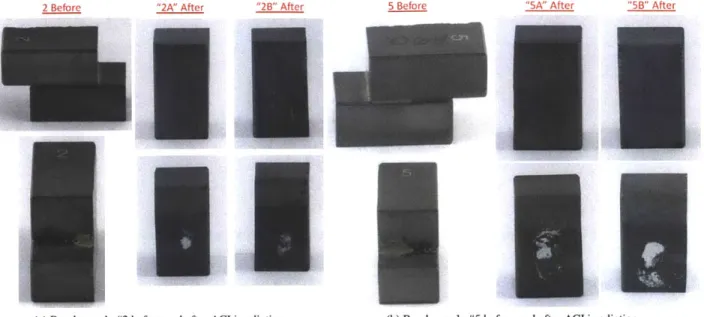
4.2 Bond samples 2 and 5 after ACI irradiation . . . . 54
4.3 Bond samples 3 and 6 before and after irradiation. . . . . 54
4.4 Bond sample 4 before and after ACI irradiation. . . . . 55
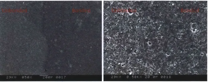
4.5 SEM of bond specimen #2 bond line . . . . 56
4.6 EDX spectra of the un-bonded and bonded regions of sample 2A . . . . 56
4.7 A series of magnifications of the white spot on sample 2A. . . . . 57
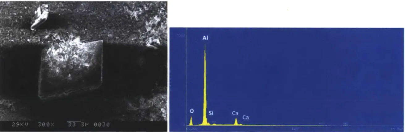
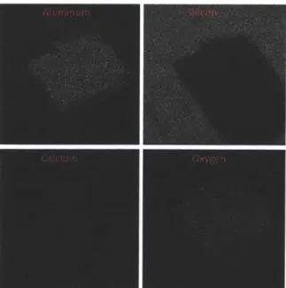
4.8 SEM and EDX of rhombohedral crystal . . . . 57
4.9 SEM and EDX of 2a white spot . . . . 58
4.10 Sample 5A calcium aluminate crystals SEM. . . . . 58
4.13 4.14 4.15 4.16 4.17 4.18 4.19 4.20 4.21 4.22 4.23 4.24 4.25 5.1 5.2 5.3 5.4 5.5 5.6 5.7 5.8 5.9 5.10 5.11 5.12 5.13 5.14 5.15 5.16 5.17 5.18 5.19
5.20 Thermal conductivity of monolith-only and Triplex SiC vs. Zircaloy-4. 95
Micrographs of the bondline region of sample 6A. . . . . 60
Comparison of the micrographs and EDX spectra from samples 3A and 6A. . . . . 61
Micrographs from the bonded region of sample 3A containing crystals. . . . . 62
SEM/EDX of titanium branches in bond sample 3A . . . . 63
Nano-sized titanium crystals in the bonded region of sample 6A. . . . . 63
EDX spectrum of dark region surrounding the bright crystals picture in Figure 4.17a. . . . . 64
SEM of sample 4 bondline . . . . 65
Complementary bonded regions of sides 4A and 4B. . . . . 66
EDX spectra for sample 4A. . . . . 66
Micrographs of the bond material from sample 4A . . . . 66
Micrographs comparing regions with and without needles in sample 4B. . . . . 67
SEM/EDX showing Ti, Al, and Si, in bond sample #4 . . . . 68
Experimental setup for determining sample density via Archimedes' method. . . . . 73
Buehler Isomet low-speed saw with sample clamps. . . . . 77
Clamps used for thermal diffusivity sample preparation. . . . . 78
Concave up and concave down views of a Triplex thermal diffusivity square. . . . . 78
Schematic and setup of LFA 447. . . . . 79
LFA 447 sample holders. . . . . 80
Thermal diffusivity specimen in sample holder . . . . 80
LFA 447 detector response vs time with and without Cowan fit. . . . . 82
Un-irradiated Triplex thermal diffusivity comparison . . . . 83
2D plot of thermal diffusivity of un-irradiated Triplex samples 04-A and 04-B. . . . . 84
2D thermal diffusivity plot of un-irradiated Triplex sample 06-B. . . . . 84
2D thermal diffusivity plot of un-irradiated Triplex sample 06-C. . . . . 85
Averaged thermal diffusivities for the 4 un-irradiated Triplex samples . . . . 86
Thermal diffusivity of un-irradiated monolithic CVD SiC . . . . 87
Thermal diffusivities for the irradiated monolithic SiC samples . . . . 88
Thermal diffusivity of monolith-only sample T-2. . . . . 89
Average thermal diffusivity of irradiated monolithic SiC tube samples . . . . 90
Thermal diffusivity of irradiated Triplex tubes . . . . 92
Average thermal diffusivity for irradiated Triplex samples . . . . 92
Irradiated vs Un-irradiated thermal diffusivities . . . . 93
List of Tables
2.1 Range of bond specimen dimensions . . . . 28
3.1 Construction and dimensions of Triplex samples . . . . 37
3.2 Pressures and hoop stresses at failure for 5 Triplex samples . . . . 41
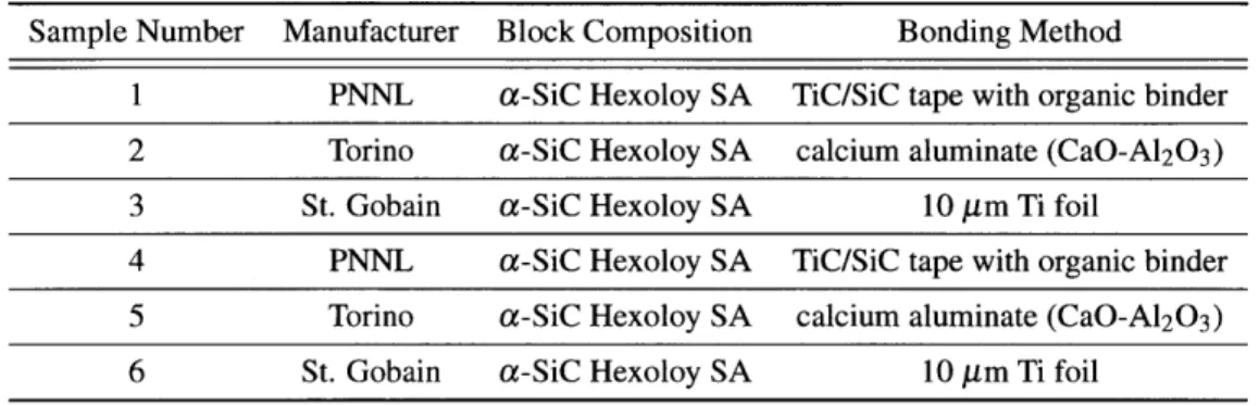
4.1 Constructions and compositions of the six bond specimens tested. . . . . 52
4.2 Bond specimen ACI exposure durations . . . . 52
4.3 Summary of weight loss in the failed bond specimens. . . . . 68
4.4 Bond specimen pre-irradiation dimensions. . . . . 69
4.5 Bond sample dimensions after irradiation . . . . 70
4.6 % relative error in the measurements listed in Table 4.5. . . . . 70
4.7 Bond specimen pre and post-irradiation dimensional comparison . . . . 71
4.8 % Difference of bond specimen dimensions pre/post-irradiation . . . . 72
4.9 Densities of irradiated bond samples and un-irradiated control samples. . . . . 74
4.10 Summary of the irradiation induced density changes in the bond specimens. . . . . 74
Nomenclature
Aptug cross sectional area of polyurethane plug
c, specific heat at constant pressure
c, specific heat at contant volume
Fadj adjusted maximum force
Fmax maximum applied force before adjustment
FptLg force to compress plug against tube inner diameter
k thermal conductivity
L sample thickness
m mass
P internal pressure at failure
q heat flux
r radius (variable)
ri tube inner radius
ro tube outer radius
t time
V volume
W dimensionless parameter from Parker et. al.
a thermal diffusivity
A phonon mean free path
v phonon group velocity
0) dimensionless parameter from Parker et. al.
p material density
Acronyms
ACI Advanced Cladding Irradiation
ATR Advanced Test Reactor
BWR boiling water reactor
CTE coefficient of thermal expansion
CTP Ceramic Tubular Products
CVD chemical vapor deposition
CVI chemical vapor infiltration
DBA design basis accident
DOE Department of Energy
dpa displacements per atom
EBC environmental barrier coating
ECCS emergency core cooling system
EDX energy dispersive x-ray spectroscopy
EFPD effective full power days
EFPY effective full power years
FCCI fuel-cladding chemical interaction
GWd giga-watt days
HNTS Hi-Nicalon Type S
LOCA loss of coolant accident LOFA loss of flow accident
LTA lead test assembly
LVDT linear variable differential transformer
LWR light water reactor
MCNP Monte Carlo N-Particle
MITR-II MIT Research Reactor
MTU mega-tons uranium
MWt mega-watts thermal
NRC Nuclear Regulatory Commission
NRL Nuclear Reactor Lab
PCMI pellet-cladding mechanical interaction
PIE post-irradiation examination
PIP polymer impregnation and pyrolysis
PNNL Pacific Northwest National Laboratory
PWR pressurized water reactor
RIA reactivity insertion accident
RPV reactor pressure vessel
SEM scanning electron microscopy
TEM transmission electron microscopy
TRISO tri-structural isotropic
1 Introduction
1.1 Background on Nuclear Fuel Cladding
With respect to materials degradation, the environment within a nuclear reactor is particularly aggressive. High tem-perature, high pressure, corrosive potentials, and neutron fluences are each, by themselves, demanding on materials. In a reactor environment, structures such as the reactor pressure vessel (RPV) and the fuel cladding are routinely subjected to all four challenges simultaneously. In a light water reactor (LWR), the integrity of the fuel cladding is so important that core thermal performance is limited, in large part, by the necessity to protect the fuel cladding from excessive thermal and mechanical stresses. [1] Contemporary LWRs' have safely operated within the limitations im-posed by the materials; however, development of advanced LWR technologies for present-day reactor designs, and future Generation IV concepts, face rigorous materials development challenges. [2]
1.1.1 Nuclear Fuel Cladding: Definition and Important Properties
Nuclear fuel cladding consists of a hollow tube in which uranium oxide (U02) fuel pellets are stacked. (Refer to Figure 2.5 for a representation of a typical LWR fuel pin.) The cladding physically separates the fuel from the coolant and acts
as a hermetic seal to prevent the release of fission products into the primary coolant system. A large pressurized water reactor (PWR), has an output of 3400 MWt and houses more than 50,000 fuel rods in its core. [3] In the Sequoyah plant in Tennessee, for example, each of the 50,000 + fuel rods is fabricated to tight tolerances: outer diameter = 9.5
mm, height = 4 m, cladding thickness = 0.57 mm. The cylindrical U0 2 fuel pellets which fill the fuel rods are also
manufactured to tight tolerances of 8.2 mm in diameter and 13.5 mm in height. The pellet centerline temperature and the fuel cladding may reach temperatures in excess of 2200 'C and 350 *C respectively. [4, 5, 6] This heat must be transferred to the working fluid (water for LWRs) in order to generate power and cool the fuel rods. Thus, a high thermal conductivity is one important material property for any fuel cladding material.
As a fuel irradiation progresses, the ceramic U02 fuel will swell as a result of the build up of internal fission
products and radiation damage. Significant thermal stresses and fission gas release cause additional anisotropic de-formation of the fuel pellet. At the beginning of a cycle, the fuel cladding itself experiences creep-down toward the pellet as a result of the pressure differential between the inside of the pellet, which is initially pressurized with helium gas to 2 MPa, and the coolant, which is pressurized to 15.5 MPa in a PWR. [7] The consequence of fuel swelling and cladding creep-down is contact between the pellet and the cladding, a phenomenon known as pellet cladding mechanical interaction (PCMI).2 In anticipation of this, the U0 2 pellets are deliberately undersized compared to the diameter of the fuel rod, leaving a gap (initially filled with helium at a pressure of 2 MVPa3) between the fuel pellet and the fuel rod. Careful design has determined the optimal size of the gap between the fuel and the cladding such that PCMI is minimized and effective heat transfer is maintained. Nevertheless, PCMI remains a serious concern because 'Contemporary reactors include Generation II and III designs. Some Generation III+ reactors (such as the AP 1000) are now under construction in China.
2
There is also a differential in the thermal expansion of the pellet and the cladding. For the commonly used zirconium alloy (zircaloy) fuel rod (to be discussed in the next section), the U03 2 pellet experiences greater thermal expansion than the zircaloy does.
its mechanisms are not fully understood, it is a cause of fuel rod failures, and it forces a limitation on the rate of reactor power ramps. [8, 9] For these reasons, any potential cladding material must possess high strength and low proclivity for creep deformation.
In addition to good heat transfer, high strength, and a low creep rate, an effective cladding must also have resistance to radiation damage and corrosive attack. Radiation damage acts to reduce the thermal conductivity and embrittle the cladding as point defects (interstitials, vacancies, etc.), ID defects (edge dislocations), 2D defects (dislocation loops), and 3D defects (voids etc.) are formed in the microstructure of the material. [10] The cladding should be chemically compatible with the fuel type (U0 2) and the coolant type (water) in order that the intended mechanical and thermal
properties of the cladding and fuel be maintained throughout their service lives. [11]
Finally, the ideal cladding material would have a high melting point and a small neutron capture cross section. A high melting point allows the cladding to maintain its structural integrity under all operating conditions as well as postulated accident scenarios. A small capture cross section ensures that the cladding has a minimal impact on the neutron economy of the reactor and low activation at the end of service. [12]
1.1.2 A Brief History of PWR Cladding: From Stainless Steel to Zircaloy-4
Stainless steel fuel cladding was used in the experimental breeder reactor EBR-I, a sodium-potassium cooled fast reactor which began operation in 1951 and was the first nuclear reactor to produce usable electricity. [13] Austenitic stainless steels were used in early reactors due to their good mechanical properties, corrosion resistance, and cost savings compared to Zircaloys. [12] Significant drawbacks to the use of austenitic stainless steel as a cladding material, however, are the large thermal neutron capture cross sections of chromium, cobalt, and traces of other elements such
as tantalum.
When EBR-I was reloaded for the second time, its "third core" utilized fuel elements clad in Zircaloy-2.4 Zircaloy-2 consists of zirconium alloyed with tin, iron, chromium and nickel. It has good corrosion resistance5, a low neutron capture cross section, and mechanical properties akin to carbon steel. [11] The first large-scale, nuclear power reactor was a PWR built in the United States at Shippingport, Pennsylvania which began operations in 1957 with Zircaloy-2 cladding. Shippingport was built as a collaboration between the U.S. Federal Government and the Duquesne Light Company. In 1961, Yankee-Rowe (a PWR) became the first fully commercial nuclear power reactor in the United
States and used mostly 348 stainless steel cladding with some test pins made of Zircaloy-2 cladding.[ 13]
In the late 1960s and early 1970s, the occurrence of cracking in zirconium alloys prompted investigations into the underlying causes. [15] A publication from 1973 was among the first to identify that this cracking was a result of hydrogen embrittlement of the zirconium alloy. [16] It was discovered that Zircaloy-2 is susceptible to hydrogen uptake which forms brittle zirconium hydrides (ZrH2). This may occur as a result of Zircaloy corrosion in water (see Section 1.3.1). Care must be also taken to minimize the presence of hydrogen in Zircaloy-2 during the manufacturing process, as this may cause hydride precipitation at grain boundaries. [11]
4
Zircaloy-2 has the following composition: 1.2 -1.7 % Sn; 0.07 -0.20% Fe; 0.05 -0.15 % Cr; 0.03 - 0.08 % Ni; 0.08 - 0.15 % 0; 0.0015 -0.003 % C; balance Zr.[14]
In boiling water reactors (BWR), which have an oxidizing environment, hydrogen embrittlement is less of a con-cern and Zircaloy-2 continues to be used as fuel cladding to this day. However, in PWRs where the water chemistry has a reducing potential, hydriding is a definite concern. Thus, Zircaloy-46 was developed to have a greater resistance to hydrogen embrittlement than Zircaloy-2. [12] Presently, Zircaloy-4 is the cladding of choice for PWRs in the United States.7 Zircaloys as a whole have been developed to the point where failure of a Zircaloy fuel cladding has become increasingly rare. [17]
1.2 A Perspective on Nuclear Materials Development
A report issued by the U.S. Department of Energy (DOE) and the Generation IV International Forum highlights several
target areas for improvement in reactor design: sustainability, economics, safety and reliability, and proliferation resistance. [18] The sustainability goals are described mainly by improved waste management and increased resource utilization. To improve waste management, the volume of nuclear wastes produced as a result of nuclear power reactor operations must be reduced and these wastes must exist in forms which have fewer long lived radioactive isotopes and lower overall levels of radioactivity. Increasing resource utilization means extracting more energy per mass of nuclear fuel. One way to increase resource utilization is to reprocess spent fuel in order to extract the remaining fissile material.
Another method for increasing resource utilization, in the absence of reprocessing or breeding programs, is to operate the nuclear fuel to higher burnup, thus extracting more energy per mass of initial fuel in the core. In the U.S., as of 2002, the average discharge burnup among PWRs was 45.7 GWd/MTU while utilizing fuels with 2 35U enrichments
of less than 4 wt %. [19] In an effort to improve fuel cycle economics and resource utilization, the current trend is towards higher discharge burnups using fuel enriched to 5 wt % 2 3 5U. [20] Currently, the U.S. Nuclear Regulatory
Commission (NRC) has limited allowable bumup to 62 GWd/MTU for select fuel types, and presently operating PWRs operate at this limit.8 [21] In addition to operating at the burnup limit, existing LWRs have received permissions for power uprates and more aggressive operation, and this, too, has placed higher demands on the materials. [22] In order to increase the discharge burnup, the average fuel rod power must be increased; or, if the rod power is to remain the same, the fuel residence time must be increased. In practice, some combination of both increased rod power and increased residence time is desirable. In any case, these approaches subject the fuel cladding to greater neutron fluences which lead to increased radiation damage in the material. In addition to increased radiation damage, increased rod power means that the fuel and cladding will operate at higher temperatures and fission gas production (and the stresses associated with it) will be increased. Longer fuel residence times will require the fuel cladding to withstand environmental degradation (such as corrosion, radiation damage, and thermal fatigue) for longer periods of time. [23] The Generation IV economics considerations aim to have competitive life cycle costs, competitive energy produc-tion costs, and competitive levels of financial risk associated with the construcproduc-tion and operaproduc-tion of the nuclear plant.
6
Composition for Zircaloy-4 (wt %): 1.2 -1.7 % Sn; 0.18 - 0.24 % Fe; 0.07 -0.13 % Cr; 0.007 % (maximum) Ni; 0.08 -0.15 % 0; 0.0015 -0.003 % C. [14]
7
Although, new zirconium alloys such as Zirlo (Westinghouse) and M5 (Areva-ANP) are proving to have improved corrosion resistance. 8 This limit applies to the core-wide peak power assembly. The core average discharge burnup will be lower.
Several approaches for improving the economics of energy production include increasing plant efficiency, increasing core power densities, and utilizing innovative materials, construction, and fabrication techniques. [18]
The Gen IV safety and reliability goals are centered on achieving low core damage frequencies and eliminating the need for off-site emergency response. [18] This may be accomplished by increasing the safety margins built into materials and structures, utilizing more passive (inherent) safety mechanisms, and improving human factors that affect nuclear power plant operations.
1.3 Limitations of Zircaloy
As was stated in the opening paragraph of this chapter, fuel performance, reactor operations, and reactor thermal performance are limited by the need to protect the fuel cladding from degradation. If the nuclear power plant were considered to be a chain, the fuel cladding would be its weakest link. It is not the weakest link because the Zircaloy cladding is a poor material, but because the operating environment that the cladding must withstand is arguably the most aggressive in the entire reactor system. If significant advances in the reactor system are desired, the fuel cladding is a prime target for improvement. The primary areas for improvement in reactor design mentioned in the Generation IV report serve as a good guide for the discussion of Zircaloy's apparent limitations. Utilities, industry, and govern-ments are all engaged in efforts to improve the sustainability, economics, and safety/reliability of existing LWRs. A discussion of these goals is as relevant to existing LWR technologies as it is to Generation IV concepts.
1.3.1 Challenges to improving the fuel cycle economics and resource utilization with Zircaloy cladding
Improving fuel cycle economics and resource utilization (sustainability) generally means that the fuel must operate to higher burnup. This means increasing the fuel residence time while maintaining the same reactor power rating, or increasing the power rating while maintaining the same cycle length, or some combination of an increased cycle length and an increased power rating. In the case of a higher power rating, the fuel and cladding will operate at higher temperatures, the coolant must flow at higher velocities, and the cladding will experience higher neutron fluences. A longer cycle length exposes the cladding to a corrosive environment for increased durations. Over this duration the primary water chemistry may change in order to protect components of the primary system and/or to control reactivity as the fuel cycle proceeds. Crud may also form and introduce sites ripe for stress corrosion cracking. [24]
Zircaloy is known to form a dark-colored protective oxide layer (ZrO2) which adheres strongly to the remaining un-oxidized Zircaloy substrate. [12] This oxidation reaction is shown below:
Zr +2H20 -> ZrO2 + 2H2.
As the cladding is exposed to high temperature water for longer periods of time, this dark, adherent film is replaced by a white, less adherent and less protecting film which results in a sharp increase in the corrosion rate. [12] This phenomenon is termed "breakaway", and there is evidence to suggest that breakaway corrosion in Zircaloy-4 may begin at burnups in the vicinity of 35 GWd/MTU. [25] Zirconium oxide (ZrO2) occupies a volume 1.5 times that of
pure Zr, and thus, reduces the mechanical strength of the Zircaloy as the oxide thickness increases. [11] Zirconium oxide also degrades heat conduction in the Zircaloy cladding. Experimental results from Motta et. al. have shown that the oxide thickness may be roughly 40 ym at 35 GWd/MTU burnup, but by the time burnup has reached 45-50
GWd/MTU, the oxide thickness has increased to between 80 and 120 ym. [25] The NRC and industry have accepted a 100 pm limit on oxide thickness, with the option, under the lead test assembly (LTA) program, to allow eight fuel assemblies from a given cycle to operate at corrosion levels predicted to be higher than 100 pm. [21] Primary water corrosion of Zircaloy cladding presents a challenge at increased burnups.
Another issue at increased burnup is the formation of hydrides on the outer surface of the Zircaloy cladding. The oxidation reaction depicted above produces zirconium oxide and hydrogen gas. This reaction occurs at the surface of the fuel rod, and if there are any perforations in the rod, it may occur on the inside of the fuel cladding as well. The net effect is that hydrogen migrates along the temperature gradient, forms brittle zirconium hydride "rims" on the surface of the cladding, and embrittles the cladding. [26] The embrittlement increases as the thickness of the hydride layer increases. Hydriding in Zircaloy becomes more and more of a concern as burnup increases. Besides embrittlement due to oxide and hydride formation, Zircaloy cladding also experiences embrittlement as a result of radiation damage which becomes more severe at higher bumups (higher fluences). [14]
1.3.2 Challenges to improving safety and reliability using Zircaloy cladding
Design basis accidents (DBA) are postulated accidents that a nuclear power plant is designed to withstand without losing the necessary systems, structures, and components required to protect public health and safety. Some of the most commonly cited DBAs are loss of coolant accidents (LOCA), loss of of flow accidents (LOFA), reactivity initiated accidents (RIA), reactor trips, and turbine trips. [6, 27] Events such as the LOCA, LOFA, and RIA events are not expected to occur at any point during the life of a reactor; nevertheless, reactors are designed with independent, diverse, and redundant systems to protect the reactor in the unlikely event that such an accident occurs. It is under
severe accident scenarios where materials, the fuel and cladding in particular, are at greatest risk.
As an example of perhaps the most severe type of accident, consider the double-ended guillotine break of the largest coolant inlet pipe to the reactor core. The reactor will undergo several phases during this accident. Each phase is characterized by different temperatures, pressures, and coolant flow rates. Following the course of events for a postulated large break LOCA illustrates the various points at which the Zircaloy cladding is at greatest risk for severe damage.
The first phase is the "blowdown phase" (which lasts for about 20 seconds) where the contents of the reactor and the inlet leg are blown down through the break in the pipe. The pressure initially falls sharply, a two-phase mixture forms, and portions of the emergency core cooling system (ECCS) are activated in order to attempt to replace coolant inventory lost from the reactor. During this first phase, the temperature of the cladding will jump because the surface of the cladding will experience dryout during the initial part of the blow down phase. Then, the cladding temperature will decrease as blow down continues which has a cooling effect by removing heat via steam from the reactor. [6] In the second phase, called the "bypass phase" (which lasts for - 10 seconds) a significant upflow of steam in the
reactor prevents the inflow of water from the ECCS. Once the bypass phase has come to an end, however, the cladding temperature will begin a steady rise. [6] The third phase is called the "refill phase" where the pressure and upward steam flow have decreased to a point where the lower plenum of the reactor core may be refilled by water from the ECCS. It may take 15 -20 seconds to refill the lower plenum once the refill phase has started. [6] After the refill phase, the "reflood phase" begins and the fuel elements will be re-wetted by water from the ECCS as the core continues to fill. In this large break LOCA scenario, the fuel cladding temperature will rise to 1000 + 'C during the reflood phase. [28, 6] The final phase is the "long-term cooling" phase where water is circulated through the core utilizing the ECCS systems (including the containment sump pump) and fuel temperature will begin to slowly decrease from its peak temperatures.
Collier and Hewitt (Reference [6]) present a summary of challenges to cladding integrity as a function of tem-perature. Between 800 'C and 1500 'C, the internal pressure of the fuel cladding will increase dramatically due to fission gases and the helium fill gases which are present. The fact that the core has depressurized means that the net internal pressure on the fuel cladding may cause the Zircaloy cladding to balloon outward and rupture or perforate. Chemical reactions between Zircaloy and stainless steel are also possible in this temperature range. Between 1450 'C and 1500 'C a highly exothermic oxidation reaction between Zircaloy and steam occurs. [6, 29] This reaction not only heats the Zircaloy further, but also embrittles it due to the uptake of hydrogen gas into the cladding. A fuel-cladding chemical interaction (FCCI) between Zircaloy and U0 2 is also possible between 1600 'C and 1800 'C. [30] In cases
where strong PCMI exits, another source reports that cladding melting may initiate at temperatures as low as 1300 'C due to the incipience of FCCI between U0 2 and Zircaloy. [31] (As a side note, strong PCMI may have a number of
causes, one of which is another design basis accident, the RIA. A reactivity initiated accident may cause an abrupt thermal expansion of the fuel pellet. When the fuel pellet comes in contact with the cladding, the cladding temperature may increase from 350 *C to 600 "C. [32] Zircaloy's response to transients such as reactor power ramps or swings in reactivity is degraded as radiation damage accumulates in the cladding.) By 1900 'C, the Zircaloy has completely melted. This discussion should illustrate the point that Zircaloy is highly vulnerable under LOCAs due, in large part, to the fact that temperatures and chemical reactions during a LOCA may exceed Zircaloy's abilities to withstand them. In 10 CFR § 50.46, the NRC has established acceptance criteria for the design of ECCS systems in LWRs. The following criteria must be met for postulated LOCAs: 1.) the peak cladding temperature must not exceed 2200 *F (1200 *C); 2.) the maximum cladding oxidation must not exceed 17 % of the total cladding thickness; 3.) the hydrogen generated from a Zircaloy-steam reaction must not exceed 1 % of the theoretical hydrogen production if all cladding in the core were to react; 4.) any change in the core geometry must be calculated to result in a geometry which is still "coolable"; 5.) long-term cooling must be sufficient to control decay heat and cool the core to acceptable levels. [33] Zircaloy cladding types are being pushed to their limits and if increased safety margins are desired, one
1.4 Silicon Carbide as a potential solution to Zircaloy's limitations.
Silicon Carbide (SiC) exhibits a number of desirable properties which support its candidacy for use as a fuel cladding in LWRs. This work will present data and evaluations of SiC samples tested under PWR conditions which are intended to support the development of SiC-based LWR fuel claddings.
1.4.1 SiC and Improved Safety/Reliability and Economics
Compared to Zircaloy, SiC is less chemically active which results in improved corrosion resistance and reduced sus-ceptibility to hydrogen embrittlement. [23] Reduced chemical activity will help to allow longer cycle lengths and provides resistance to deleterious chemical reactions under accident conditions (i.e. LOCA, RIA, etc.). Another positive attribute is SiC's ability to maintain strength at high temperatures (1600+ C), allowing for higher power den-sities (reduced capital costs), and better performance under thermal variations that may occur as a result of transients. [34, 35] Highly pure SiC has a published melting point of 2545 "C compared to Zircaloy's melting point of 1900 "C.
SiC has a high thermal conductivity (which exceeds that of nearly all other ceramics and some metals), a low thermal expansion coefficient, and a lower creep rate than Zircaloy. A high thermal conductivity and a low thermal expansion coefficient make SiC less susceptible to thermal shock as a result of LOCA or RIA accidents. These qualities all help to improve the economics and safety margins of a nuclear power plant.
1.4.2 SiC and Improved Sustainability: Resource Utilization and Waste Management
While Zircaloy may represent a neutronic improvement over stainless steel, SiC is a neutronic improvement over Zircaloy. Silicon carbide has a lower thermal neutron absorption cross section (oT,,) which aids the neutron economy in the reactor and allows SiC to withstand higher neutron fluences since radiation damage from neturon absorption will accumulate more slowly. Improved neutronic properties and resistance to radiation damage will improve fuel utiliza-tion by allowing longer cycle lengths and higher burnups beyond the present limit of 62 GWd/MTU. Addiutiliza-tionally, SiC is inherently a low activation material which will make it easier to dispose of when its core residence time has come to an end. [36] These properties of SiC would allow improvements in the areas of sustainability and waste management.
1.5
Objectives and Scope
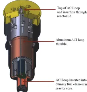
The majority of the work conducted involved the post-irradiation examination (PIE) of prototype three-layered (Triplex) tubular SiC cladding designs and several methods for bonding distinct SiC pieces together. Samples of different con-structions were placed in the Advanced Cladding Irradiation (ACI) test loop inside the MIT research reactor
(MITR-II) and irradiated under PWR coolant conditions. At various intervals, samples were removed from the test loop
and inspected for dimensional changes, corrosion, degradation of mechanical properties, and degradation of thermal properties.
Various sample preparation and analysis methods were developed in order to collect these data. A new xenon-flash instrument was used to measure the thermal diffusivity of irradiated and un-irradiated samples. This allowed
the relative quantification of the extent of radiation effects. The thermal diffusivity of single-layered SiC tubes was compared to Triplex SiC tubes as well. An in-house burst test was used to determine the hoop strength of irradiated and un-irradiated Triplex designs. Dimensional, mass, and volume measurements were used to help understand the fate of SiC/SiC bond specimens. Scanning electron microscopy (SEM) and energy dispersive X-ray spectroscopy (EDX) were used to help characterize sample surfaces and observe damage phenomena from the burst tests and bond specimens.
2 Introduction to SiC: Crystal Structure, Manufacture, Test Materials, and
Test Conditions
Silicon carbide is a ceramic, which, generally speaking, is a term used to describe a non-metallic, inorganic material with a high melting point. More specifically, SiC is a member of a subcategory of ceramics called "structural ceramics" which are characterized by their high strength, high hardness, and strong wear resistance. [37]
2.1
SiC Crystal Structure
Silicon carbide's various properties can be attributed to its crystal structure. Silicon carbide is known to form more than 200 different polytypes (crystal structures) which arise as a result of different periodic stacking of six molecular
"bilayers".9 (Figure 2.1) Each bilayer consists of two close packed planes of Si and C. Unit cells having even numbers of bilayers have hexagonal symmetry, and unit cells with odd numbers of bilayers are cubic (or rhombohedral). Rhom-bohedral and hexagonal SiC polytypes are termed ot-phase SiC (o-SiC) and cubic SiC is called n-SiC. A shorthand known as the Ramsdell notation is used to describe the various SiC polytypes. In the Ramsdell notation, a number de-noting the number of bilayers in the unit cell comes first, followed by a C, H, or R which denotes the crystal symmetry (cubic, hexagonal, or rhombohedral). For example, in Figure 2.1, "3C" represents a unit cell of three bilayers with cubic symmetry. The "6H" crystal of SiC has six bilayers with hexagonal symmetry. The most common polytypes of SiC are 3C (#-SiC), 4H, 6H, and 15R (with the latter three all considered a-SiC). [38] It is said that the stacking order of the different polytypes does not result in significant differences in physical properties. [37]
3C CA 4H bc b6H aB bc+cA bC A1+C aC-c
B-Figure 2.1: Four common polytypes of SiC, each comprised of stacks of different bilayers of Si and C atoms. Adapted from [39].
When the bilayers stack together, they form tetrahedra of Si4C or SiC4 as shown in Figure 2.2. The bonds between the Si and C atoms have a primarily covalent nature, with slight ionic bonding characteristics due to silicon having a higher electronegativity than carbon. The dominant covalent nature dictates that the most stable SiC structures are
9
Figure 2.2: Tetrahedral arrangement of Si and C atoms. In the SiC crystal structure, the central (red) atom may be a C while the outer (blue) atoms may be Si atoms, or vice versa.
2700 2000 I (~d Q U) 1415 1! U U) 6 0 2O 30 40 50 C at. % 60 10 O
Figure 2.3: Binary phase diagram for SiC.
p-SiC
is more stable at lower temperatures, but undergoes a phase change to a-SiC at higher temperatures (-2000 *C). [40] The shading represents a single-phase field while the white background represents as two-phase field.comprised of Si and C in stoichiometric (1:1) amounts. For stoichiometric SiC, phase stability is a strong function of temperature with (3C)
#-SiC
reported to be more stable at lower temperatures, while a-SiC dominates the high temperature regime as depicted in Figure 2.3.2.1.1 Mechanical Properties of SiC
Silicon carbide, due to its crystallinity, is susceptible to brittle fracture. However, as will be discussed later in this thesis, novel manufacturing techniques can eliminate (or at least mitigate) the extent of brittle fracture in SiC materials. Brittle fracture is a process by which cracks form and propagate through a cross section of the material in a direction perpendicular to the direction of the imposed load. At room temperature, most ceramics will experience fracture prior to any plastic deformation. For plastic deformation to occur in ceramics, dislocations in the crystal structure must be able to diffuse in response to the applied stress. Ceramics such as SiC are hard and brittle because the motion of the dislocations (slip) is very difficult owing to few slip systems along which the dislocations may travel. [41]
E I 3200- 300- 2800- 2600- 2400- 2200- 2000- 1600- 1400- 1200- 1000-a00 W) 90 160 Si KM
Generally, measured fracture strengths of ceramic materials are lower than those predicted from a consideration of the bond strengths. This is due to the unavoidable presence of flaws in the crystal structure of a ceramic. Flaws act to concentrate and amplify applied stresses which leads to the formation of cracks. Flaws may exist in the material as a result of the manufacturing and processing of the ceramic, or as a result of neutron damage, or as a result of applied mechanical stresses. It is impossible to eliminate all flaws in a crystalline material.
2.1.2 Thermal Conductivity in SiC
Thermal conduction is the transfer of heat from a region of high temperature to a region of lower temperature within a particular substance. The thermal conductivity of a material is a quantity which describes the ability of that material to transfer heat. Equation 1 represents Fourier's heat conduction equation for steady-state conditions.
q" = -kVT (1)
Here, q" represents the heat flux (heat flow per unit area per unit time), k is the thermal conductivity, and VT is the temperature gradient through at 3-dimensional conducting medium. Typical units for the three parameters are as follows: q" = [W/m2], k = [W], and VT = [K/m]. The thermal conductivity is related to the thermal diffusivity via the following relation:
k
a =- (2)
where a is the thermal diffusivity (having units of [m2/s]), k is the thermal conductivity, p is the bulk density, and
cp is the specific heat of the material at constant pressure (with units of [k/K]). Thermal diffusivity is most often
measured using a thermal flash technique to be described later in this thesis. The specific heat may be measured using a differential scanning calorimeter, and the density of the specimen is most often measured using either a liquid density gradient column technique or Archimedes' method.
There are two main modes by which heat may be transported in solid materials: the movement of free electrons and/or the travel of vibrational lattice waves (also known as phonons). [41] Atoms in the crystal lattice vibrate due to thermal energy. If an atom gains or loses thermal energy, its vibrational frequency will increase or decrease (respec-tively) and this change will be transmitted to other, nearest neighbor atoms through the atomic bonds. This results in traveling lattice waves and the transport of phonons. As a semi-conductor, SiC has a low density of valence band electrons which means that phonons are the primary mode of thermal energy transport in SiC. Defects in the crystal structure play a large role in the scattering of phonons and, thus, the ease of heat conduction in SiC. Phonons may be scattered by irradiation-induced point defects (vacancies and interstitials), defect clusters (voids and dislocation loops), grain boundaries, and phonon-phonon interactions (known as umklapp scattering). [42] Each type of phonon scattering tends to operate over different energy ranges and may be considered separable such that the overall thermal resistance of a material is the sum of the thermal resistances due to each type of phonon scattering. (Equation 3) Here,
k is the total thermal conductivity, and the reciprocal of the thermal conductivity is the thermal resistivity.
1 I-= _ 1 1 1
I + I + 1(3)
k kgrainboundary kumklapp kdefect
Low temperature irradiation of SiC (200 -800 *C) tends to produce point defects which very effectively scatter phonons
and reduce the thermal conductivity/diffusivity. By the time a ceramic has been irradiated to a damage state of a few displacements per atom (dpa), the effect of phonon-defect scattering dominates over other types of phonon scattering, and the reduction of thermal conductivity reaches a saturated state. Moreover, when phonon-defect scattering exceeds phonon-phonon scattering, the temperature dependence of the ceramic's thermal conductivity is greatly weakened.
[42] See Section 3.3.2 for a description of dpa estimates for SiC under neutron irradiation.
An alternative expression for the thermal conductivity in SiC which is seen frequently in the literature draws on an analogy to the kinetic theory of gases. For an isotropic solid, the thermal conductivity may be given by the following:
k = -vcA (4)
3
where k is the thermal conductivity, v is the phonon group velocity, c, is the specific heat at constant volume, and A is the phonon mean free path. [43] The phonon mean free path is limited by impurities, grain boundaries, irradiation-induced defects, and phonon-phonon scattering. [44]
2.2
Some Applications of SiC
Owing to SiC's hardness, wear resistance, high melting point, electrical conductivity, low neutron cross section, and other desirable properties, SiC has found many uses. For years, SiC has been used as an abrasive, a refractory, and as a resistive heating element in electric furnaces. SiC also features in automotive water pump seals, ballistic armor, roller bearings, and heat exchangers. SiC has been being used as the primary fission product barrier in TRISO (tri-structural isotropic) fuels for gas-cooled nuclear reactors and as diagnostic temperature monitors for radiation environments. SiC is also being considered as a first-wall material for nuclear fusion reactors and as fuel cladding for LWRs.
2.3
Introduction to SiC Samples
The experiments and findings herein are based primarily on two SiC test materials: 1.) a tubular SiC LWR-type cladding and 2.) bonding materials for bonding two distinct SiC pieces together such that the bond can survive PWR operating conditions with adequate margin. The two material types are described in Sections 2.3.1 and 2.3.2, and manufacturing methods relevant to SiC are described in Section 2.3.3.
2.3.1 Triplex Silicon Carbide Cladding Design
Since 1999, Gamma Engineering has been developing and testing SiC cladding for commercial LWRs. In 2005, Gamma Engineering and Innovative Technologies International (NovaTech) formed a joint venture called Ceramic
Tubular Products, LLC (CTP). CTP and its partners have expressed a number of goals for the SiC cladding designs including: allowing an increase in burnup to at least 80 GWD/MTU, reducing operating fuel failures, and improving safety margins for DBAs such as LOCAs and RIAs.
Previous CTP Design Previous work at MIT involved duplex SiC cladding designs. [45, 23] The duplex designs
consisted of a dense, inner monolith of SiC and an outer, composite layer made of woven SiC fibers. The monolith is manufactured via a process called chemical vapor deposition (CVD). The SiC fibers are woven around the monolith, and then a SiC matrix fills the voids in the woven composite via a process of either chemical vapor infiltration (CVI) or polymer impregnation and pyrolysis (PIP). The monolithic SiC serves to provide hermeticity in order to contain fission gases, and the outer SiCf/SiC composite layer helps reinforce the monolith and provide a "graceful" failure mode
should the tube rupture during an accident. See Section 2.3.3 for a more detailed description of relevant manufacturing methods.
Current CTP Design The investigation of Triplex SiC cladding designs began more recently and continues at the
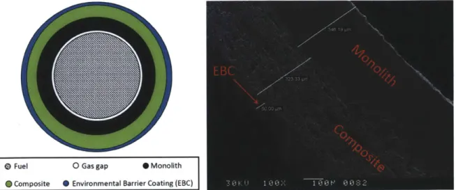
time of this writing. As the name implies, the Triplex cladding designs, illustrated in Figure 2.4 have three parts: 1.) a dense inner monolith, 2.) a composite layer of SiC fibers woven in a SiC matrix, and 3.) a thin outer layer of SiC called an environmental barrier coating (EBC). As mentioned in the previous paragraph, the monolith is manufactured via a process of CVD. For the composite layer, the SiC fibers are woven around the central monolith, and a CVI process is used to fill the void space within and around the fibers with additional SiC. The monolithic SiC serves to provide hermeticity in order to contain fission gases, and the outer SiCf/SiC composite layer helps reinforce the monolith and provide a pseudo-ductile failure mode should the tube rupture during an accident. The EBC is a thin (50-150 pm)
SiC coating applied to the outside of the composite layer in order to protect the composite layer of the cladding from corrosion. Previous experiments have shown that, when loaded internally, the composite and EBC layers may share between 21.6 % and 37 % of the total hoop load. [46] The monolith, thus, is the primary load bearing structure in the Triplex design.
The dimensions, and uniformity of dimensions, vary from sample to sample. The samples were made in very small volumes on a lab scale. In most cases, the monolith and composite layers are each about 50 % of the total tube wall thickness of the Triplex samples. Table 3.1 summarizes the dimensions and construction of five representative Triplex samples.
In this work, samples consisting of only a monolith layer will be referred to as "monolith-only" samples. Samples consisting of the three layers described above, and depicted in Figure 2.4, will be called "Triplex" samples. The layer consisting of SiC fibers in a SiC matrix, will be referred to as the "composite" layer. This is consistent with the terminology used in [45], [46], and [47].
* Fuel 0 Gas gap 0 Monolith * Composite 0 Environmental Barrier Coating (EBC)
(a) Illustration of the Triplex cladding design. (Not drawn to (b) SEM micrograph showing the three layers of the Triplex tube.
scale.)
Figure 2.4: Illustration and SEM micrograph of the Triplex cladding design.
2.3.2 Bonded-Block Specimens: SiC/SiC Bonding Study
As illustrated in Figure 2.5, after fuel pellets have been loaded into a fuel rod, the top of the rod must be sealed tightly with an end cap in order to retain the helium fill gas and any fission gases produced. On top of the last U0 2 pellet is an
insulating pellet (often made of alumina), and pressing down on top of the insulating pellet is a spring located between the end cap and the insulating pellet. The spring is used to keep the fuel pellets firmly located at the bottom of the fuel rod. The space occupied by the spring is a plenum which allows for the accumulation of gases. The material used to plug the top of the fuel rod must be able to withstand the same environment as the rest of the rod. Additionally, the end cap should have the same (or similar) thermal expansion coefficient, swelling behavior, thermal conductivity,
hardness, etc. as the material used for the cladding itself.
For fuel pins clad in Zircaloy, the Zircaloy end cap is welded into place. However, for the proposed ceramic SiC cladding, a different means for sealing the end cap to the top of the cladding will be needed. In order to test several methods for bonding a SiC end cap to the top of a SiC fuel rod, several blocks bonded together via different methods were irradiated in the ACI test loop in the MITR-II under the same conditions used to test the Triplex specimens.
End Cap
Plenum
Insulating Pellet
I
1
/7
U0
2Fuel Pellet
I
Spring
Cladding
Figure 2.6 shows the general construction of the "bonded block" specimens'0, and Table 2.1 shows a range of values for the dimensions labeled in Figure 2.6. Dimensions specific to each bond specimen before and after irradiation can be found in Tables 4.4 and 4.5 respectively. The figure on the left in Figure 2.6 shows that two blocks of equal size and construction are bonded together on their broadest faces such that a certain length of each block is left "free" or un-bonded. The figure on the right of Figure 2.6 depicts an edge view of the blocks.
Each block is an a-phase SiC product called Hexoloy SA* manufactured by Saint-Gobain. Hexoloy SA® is formed by pressureless sintering of a submicron-size SiC powder which results in a self-bonded, fine grain SiC block with a manufacturer specified density of approximately 3.10 g/cm3 compared to a theoretical density of 3.21 g/cm3for a-SiC. A natural boron (B4C) sintering aid in 0.6 w/o quantities is used in the manufacturing process.
a
e
bf
C g
Figure 2.6: Diagram showing the construction of bonded block specimens.
Six bond specimens were irradiated in total, and three bonding methods were used to fabricate these six specimens. Thus, method 1 was used for two of the samples, method 2 was used for two samples, and method 3 was used for two samples. One bonding method used a TiC/SiC tape with an organic binder. A second method used a type of glass-ceramic called calcium aluminate (CaO-A1203). The third method bonded the two halves together by placing a 10 Am Ti foil between the two halves, heating the two halves, and then pressing them together under 30 MPa of pressure. To fabricate each specimen, two larger blocks of Hexoloy SA were bonded together. These blocks, now bonded, were cut length-wise to give two "identical" specimens bonded with the same method under the same conditions.
2.3.3 Relevant Manufacturing Techniques
In nature, silicon carbide exists as the rare mineral known as moissanite. A methodology for producing synthetic SiC was patented by Edward Acheson in 1893. In order to produce bulk SiC for use as an abrasive, Acheson formed the company Carborundum, which continues to produce SiC to this day. The Acheson process [48] combines carbon from coal derivatives (coke) with silica (SiO2) or aluminosilicates (A1203-SiO2) and heats the combination in a resistance furnace resulting in SiC via the general reaction in Equation 5.
SiO2 + 3C -> SiC + 2CO (5)
10A bonded block specimen consists of the two halves that make up the bonded pair. If reference is being made to a half of the bond specimen, it

![Figure 3.1: Simplified illustration of the hoop test apparatus. Adapted from [57].](https://thumb-eu.123doks.com/thumbv2/123doknet/14150925.471778/35.918.218.673.181.421/figure-simplified-illustration-hoop-test-apparatus-adapted.webp)