Publisher’s version / Version de l'éditeur:
Vous avez des questions? Nous pouvons vous aider. Pour communiquer directement avec un auteur, consultez la première page de la revue dans laquelle son article a été publié afin de trouver ses coordonnées. Si vous n’arrivez pas à les repérer, communiquez avec nous à PublicationsArchive-ArchivesPublications@nrc-cnrc.gc.ca.
Questions? Contact the NRC Publications Archive team at
PublicationsArchive-ArchivesPublications@nrc-cnrc.gc.ca. If you wish to email the authors directly, please see the first page of the publication for their contact information.
https://publications-cnrc.canada.ca/fra/droits
L’accès à ce site Web et l’utilisation de son contenu sont assujettis aux conditions présentées dans le site LISEZ CES CONDITIONS ATTENTIVEMENT AVANT D’UTILISER CE SITE WEB.
International Thermal Spray Conference (ITSC) 2010 [Proceedings], 2010-05-03
READ THESE TERMS AND CONDITIONS CAREFULLY BEFORE USING THIS WEBSITE.
https://nrc-publications.canada.ca/eng/copyright
NRC Publications Archive Record / Notice des Archives des publications du CNRC :
https://nrc-publications.canada.ca/eng/view/object/?id=249f2a59-3de0-46ae-a0cf-18f2889dfcc1
https://publications-cnrc.canada.ca/fra/voir/objet/?id=249f2a59-3de0-46ae-a0cf-18f2889dfcc1
NRC Publications Archive
Archives des publications du CNRC
This publication could be one of several versions: author’s original, accepted manuscript or the publisher’s version. / La version de cette publication peut être l’une des suivantes : la version prépublication de l’auteur, la version acceptée du manuscrit ou la version de l’éditeur.
Access and use of this website and the material on it are subject to the Terms and Conditions set forth at
Mechanical Properties and Behaviour of BSAS/mullite-based
Environmental Barrier Coatings Exposed to High Temperature in Water
Vapour Environment
Mechanical Properties and Behaviour of BSAS/mullite-based Environmental Barrier
Coatings Exposed to High Temperature in Water Vapour Environment
C.V. Cojocaru, S. E. Kruger and R.S. Lima
National Research Council of Canada (NRC), Boucherville, QC, Canada
C. Moreau, Institut national de la recherche scientifique (INRS), Montreal, QC, Canada
Si-based ceramics (e.g., SiC and Si3N4) are known as promising high-temperature structural materials in various
components where metals/alloys reached their ultimate performances (e.g., advanced gas turbine engines and structural components of future hypersonic vehicles). To alleviate the thickness recess that Si-based ceramics undergo in a high-temperature environmental attack (e.g., H2O vapour), appropriate refractory oxides are
engineered as environmental barrier coatings (EBCs). Presently, the state-of-the art EBCs comprise multilayers of silicon (Si) bond coat, mullite (Al6Si2O13) intermediate layer and BaO-SrO-Al2O3-SiO2 (BSAS) top coat. Evaluating
and understanding their mechanical properties, such as, the elastic modulus (E) and the strain-stress relationship is essential for their practical application and reliable employment. It was investigated via depth-sensing indentation the role of high-temperature treatment (1300oC), performed in H2O vapour environment (for time intervals up to 500
h), on the mechanical behaviour of air plasma sprayed Si/mullite/BSAS layers deposited on SiC substrates. Laser-ultrasonics was employed to evaluate the E values of as-sprayed coatings and to validate the indentation results. The fully crystalline, crack-free and near crack-free as-sprayed EBCs were engineered under controlled deposition conditions. The (i) absence of phase transformation and (ii) stability of the low elastic modulus values (e.g., ~60-70 GPa) retained by the BSAS top layers even after harsh environmental exposures provides a plausible explanation for the almost crack-free coatings observed. The measured mechanical properties of the EBCs and their microstructural behaviour during the high-temperature exposure are discussed and correlated.
1 Introduction
To increase the efficiency of a gas turbine engine higher operating temperatures are needed. In the same time the durability of the engine components must correspondingly sustain the temperature increase. While metal super alloys are widely used for various engine components, alternative materials and in particular silicon (Si) based ceramics (e.g., SiC and Si3N4) emerged for high temperature applications due
to their high mechanical strengths at high temperatures and density values in the order of 1/3 of those of metallic superalloys. For most of these applications protective coatings are beneficial and even required. Layered refractory oxide coatings offering a suitable thermal-insulation reduce the thermal gradient through the structural component and increase its durability. A coating for components formed of Si-based materials must simultaneously fulfill a second role namely environmental protection, like for instance, in high temperature environments containing water vapours or corrosive molten salts. Thus these coatings have been named environmental barrier coatings (EBCs) [1-3].
Regarding gas turbines, a low permeability for oxidant species is a critical feature for an EBC system so as to inhibit the major degradation mechanism of the Si-based substrate that is formation of silicon hydroxide (Si(OH)4) gas by the reaction of the water vapour
originating from the jet fuel combustion with the SiO2
scale formed on the Si-substrate [1-3]. The future hypersonic vehicles flying in low Earth orbit will also
employ Si-based materials on its external structure. For this type of application, a silicon monoxide (SiO) scale will tend to be formed on the surface of these Si-based materials due to the low O2 pressure at high
altitudes and the high temperatures caused by the friction with the atmosphere during ascending and re-entry. The SiO scale will tend to sublime under these conditions. Therefore, EBCs will be needed for the external structure of hypersonic vehicles [4].
In brief the requirements for an efficient EBC system could be outlined as follows: (i) good chemical compatibility and good adherence (offered mainly by a coefficient of thermal expansion (CTE) match) with the substrate, (ii) low thermal conductivity, (iii) crack resistance (offered by phase stability, low stress, i.e., low elastic modulus and sintering resistance), and specifically for gas turbines, (iv) H2O vapour stability
and durability for molten salts corrosion [1-4].
The current state-of-the-art EBC system, which follows the four requirements mentioned above, comprises a Si bond coat, a mullite (Al6Si2O13) intermediate layer
and a BaO-SrO-Al2O3-SiO2 (BSAS) crack-resistant
and water vapour attack resistant top coat [1-3]. Evaluating and understanding EBCs mechanical properties, such as, the elastic modulus and the strain-stress relationship is essential for their practical application and reliable employment.
The elastic properties of as-sprayed and thermally treated Si/mullite/BSAS EBCs in water vapour environment and the evolution of phase composition of thermally sprayed BSAS have been scarcely reported in the literature. In this work it was
investigated via depth-sensing indentation the role of high-temperature treatment (1300oC), performed in H2O vapour environment up to 500 h, on the
mechanical behaviour of air plasma sprayed Si/mullite/BSAS EBCs deposited on SiC substrates, as well as, the phase evolution of these coatings. Laser-ultrasonics was employed to evaluate the E values of as-sprayed coatings and to validate the indentation results.
2 Experimental
2.1 Sample preparation
The powders employed in these studies were the following: (i) silicon (Si) (Si-1168, Cerac Inc., Milwaukee, WI, USA, (ii) mullite (Al6Si2O13) (M_SG),
(#1020, Saint-Gobain Worchester, MA, USA) and (iii) barium strontium alumina silicate (BaO-SrO-Al2O3
-SiO2) (BSAS) (Amperit 870.084, H.C Starck, Newton,
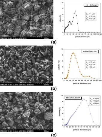
MA, USA). The particle size distribution was evaluated using a laser scattering particle size analyzer (LS 13320, Beckman Coulter, Miami, FL, USA). The morphology of the powders analyzed via scanning electron microscopy (SEM) and their respective particle size distributions are shown in Fig.1.
(a)
(b)
(c)
Fig. 1. SEM micrographs and particle size
distributions of the (a) Si, (b) mullite, and (c) BSAS powders used during the depositions.
Prior to the spraying the phase composition of each powder has been determined via X-ray diffraction
(XRD) (D8-Discovery, Brucker AXS Inc., Madison, WI, USA) using Cu-Kα radiation in Bragg-Brentano (θ-βθ) configuration.
Using an air plasma spray (APS) torch (Axial III, Northwest Mettech, North Vancouver, BC, Canada) the powders were sprayed onto 5 x 5 cm SiC substrates (Hexaloy SA, Saint-Gobain, Niagara Falls, MA, USA). In-flight particle temperature and velocity values were measured (DPV 2000, Tecnar Automation, St-Bruno, QC, Canada) and the substrate temperature monitored with an infrared camera (SC 620, Flir Systems AB, Danderyd, Sweden). Fully crystalline as-sprayed coatings were engineered for each type of powder by employing a proprietary technology of the National Research Council of Canada (NRC).
2.2 Structural characterization
As a general sample preparation procedure, once completing the spraying process, the 5 x 5 cm coupons were cut in quarters for thermal treatment (TT) and structural/mechanical analysis. As a standard test to screen EBC performance, thermal treatment tests were performed at 1300oC in a continuous flow of H2O vapour (90%H2O/10%air) as an attempt to
simulate the environment of a gas turbine [1-2], for time intervals up to 500 h using an in-house developed EBC rig and based on a high-temperature tube furnace (STT-1700-2.0-18, SentroTech, Berea, OH, USA).
The crystallinity of the as-sprayed and thermally treated coatings was analyzed via (θ-βθ) X-ray diffraction technique. Samples were embedded in epoxy prior to cross-section cutting and further prepared by standard metallography procedures for SEM (S4700, Hitachi, Tokyo, Japan) analysis and instrumented indentation testing (IIT) (Nanoindenter G200, Agilent Technologies, Oak Ridge, TN, USA).
2.3 E measurements via instrumented
indentation testing
Using depth-sensing indentation (Oliver-Pharr method) with a Berkovich diamond tip, the elastic modulus (E) values of each deposited coating were measured at room temperature on the polished cross-section of the samples. Since the applied indentation loads and their corresponding penetration depths are measured continuously during an loading-unloading cycle, the residual hardness impression does not have to be directly imaged as in conventional microhardness testing. This represents one of the main advantages over the more traditional indentation measurements.
Measurements were performed at loads between 10-500 mN with loading times of 15 s and unloading (90% of the segment recorded) times of 20 s. For each coating several sets of 15-20 indents were performed generally spaced at distances correlated with the load applied. The E values of the material is calculated based on the initial portion of the unloading curve as the unloading is the purely elastic recovery process.
This gives the elastic stiffness of the contact S and serves to initially determine the reduced elastic modulus (Er) (with a numerical factor =1 for the triangular cross-sections like the Berkovich tip):
dh
dP
S
where P is the load applied on the test surface and h is the indenter displacement and
A S E
r
2
where A is the projected area at that load. The E value of the tested coating is calculated making use of the reduced Er using the formula:
i i r E E E ) 1 ( ) 1 ( 1 2 2
where Ei=1141 GPa and Poisson’s ratio νi=0.07 are the indenter diamond tip properties used for calculations. In these measurements it was assumed the Poisson ratio’s of the tested coatings to be 0.25, which is an average values used for ceramic materials. In fact, such rough estimation (ν = 0.25±0.1) produces only about a 5% uncertainty in the calculated value of E for most materials. More information about this methodology can be found elsewhere [5].
Four different loads (i.e., 10, 100, 250 and 500 mN) were applied either in form of arrays or on selected locations. Areas with high porosity were intentionally avoided. Indentations were made on all coatings and also on the substrate. Indentation residual impressions given at 500 mN load are depicted in the SEM micrographs shown in Fig. 2.
(a) (b)
Figure 2. Indentation testing residual impression
made with a Berkovich diamond tip into a (a) mullite and (b) BSAS layers for 500 mN (50 gf) load.
Surface polishing of the cross-sectioned ceramics is a delicate issue. The so-called “pull-outs” or voids are produced in the surface and indentations are not always easy to position due to an increased porosity. However, suitably dense areas were chosen to be indented but, nevertheless, the porosity that might lie underneath the indent location cannot be predicted or avoided.
2.4 Laser-utrasonics measurement of E values
Elastic modulus of fully crystalline as-sprayed mullite, and BSAS layers, each sprayed independently on SiC substrates, were also determined via a laser-based ultrasonic tecnique in order to compare the latter with the values obtained via IIT. Elastic modulus were calculated from the ultrasonic velocity measured using a laser-ultrasonic experimental set-up equipped with a pulsed Nd:YAG laser (3rd harmonic: 355 nm wavelength, 35 ps pulse duration) employed to generate surface acoustic waves. This generation laser, in the ultraviolet wavelength with very short pulse duration, is chosen to get optimal generation efficiency. For the detection, a long-pulsed Nd:YAG laser (1064 nm wavelength, 200 s pulse duration) was coupled to an GaAs photorefractive interferometer by optical fibers. This photorefractive interferometer provides enhanced sensitivity on unpolished surfaces and reliable response to lower ultrasonic frequencies. A detailed set-up description of laser ultrasonic measurements of elastic constants on coatings is given elsewhere [6].
3 Results and discussion
3.1 Microstructural analysis
XRD patterns reveal fully crystalline as-sprayed Si bond coat, mullite and BSAS coatings engineered via an NRC proprietary technology (Fig. 3). No amorphous or foreign phases were detected (e.g. -alumina into mullite). Energy-dispersive X-ray (EDX) chemical analysis (not shown) did not reveal foreign elements in either mullite or BSAS coatings. Also, after thermal treatment in water vapour at 1300oC, no significant phase transformation was detected up to 500 h. These results demonstrate the high phase stability of fully crystalline BSAS coatings in water vapour environments and helps to explain its choice as a state-of-the-art EBC coating.
The SEM micrograph of the as-sprayed EBC (Fig.
4(a)) shows that the Si bond coat appears as a dense
and crack-free layer exhibiting good adhesion (i.e., no gaps) to the substrate and also to the upper crack-free mullite intermediate layer. It can also be observed from the absence of delamination between the mullite layer and the near-crack free BSAS top coat. Concerning the thermally treated EBCs (Figs.
4(b)-(c)), it was observed the formation of pores in the
mullite coating next to the Si bond coat interface. Previous authors already observed this event and attributed it to the water vapour corrosion [1], which probably penetrated thorough the coating porosity.
(a)
(b)
(c)
Figure 4 (a), (b) and (c). SEM micrographs of the
Si/mullite/BSAS EBCs before and after thermal treatment at 1300oC in water vapour environment.
Nonetheless, it is important to point out that for the thermal treated EBCs, no debonding, delamination or cracking was observed after 500 h.
3.2 Interfaces
When the interface of the as-sprayed Si bond coat and SiC substrate of the tri-layer EBC is observed at higher magnifications, it is possible to notice the presence of a thin silica layer (~0.5 µm), Fig. 5(a). No significant growth of this silica layer was observed after an exposure at 1300oC for 165 (Fig. 5(b)) and 500 h (Fig. 5(c)) in water vapour environment.
(a)
(b)
(c)
Fig. 5 (a), (b) and (c). SEM details of the interface
between the Si bond and SiC substrate before and after thermal treatment at 1300oC in water vapour environment.
However, the uncoated surface of the substrate (Fig.
6) exhibits a much thicker (~5 µm) and low-adherent
SiO2 layer (composition verified by EDX). Therefore,
this EBC system produced in this study protected effectively the SiC substrate against oxidation and water vapour attack, showing the same trend also observed by other authors [1-3].
Fig. 6. SEM detail of the SiO2 layer thermally grown on
the uncoated SiC substrate.
Mechanical testing via IIT and the indentation size effect
The influence of indentation load on E and hardness values of ceramics has been investigated by several groups and it was reported that both exhibit significant dependence on the indentation load [7]. A general trend is that elastic moduli tend to decrease with the increase of the load applied [8]. To investigate these phenomena measurements were performed on the deposited coatings by varying the indentations loads from 10 to 500 mN in order to search for the interval values of the applied force at which the E data obtained stabilized.
It is observed in the graphs presented in Fig. 7 that within the load interval 250-500 mN, the E values tended to stabilize and at this point it is hypothesized that the measured E values represent a global perspective on the material (useful for engineering purposes) and not small volumes of its microstructure. The size of the indentation impressions (triangle size ~15 µm) at loads of 500 mN (Fig. 2) supports this hypothesis. A typical APS ceramic splat exhibit thicknesses in the order of 1 µm [9]. Therefore, when areas representing triangular impression sizes of ~15 µm are probed, a group of many splats is likely to be tested, i.e., not just one single or few. For example, volumes probed at 500 mN (Fig. 2) are ~80 µm3. In order to validade this hypothesis, the E values of fully crystalline mullite and BSAS coatings, sprayed independently on SiC substrates, were measured via laser-ultrasonics, and compared with those of IIT obtained using the 500 mN load. The choice for this comparison is based on the fact that the E values measured via laser-ultrasonics do represent the overall coating microstructure. The results can be found in Table 1. The E values obtained via
laser-ultrasonics represent an average of 100 laser pulses. The ratio between the E values measured via IIT and laser-ultrasonics for the as-sprayed mullite and BSAS coatings were 1.1 and 0.9, respectively; i.e., they are very similar. This is another evidence that the E values measured via IIT at 500 mN load tend to represent the global perspective of the coating microstructure.
Fig. 7. E values versus indentation load (from 10 to
500 mN) for as-sprayed mullite and BSAS coatings.
Table 1. E values measured via IIT at 500 mN (50 gf)
load and laser-ultrasonics for as-sprayed mullite and BSAS coatings.
Coating IIT 500 mN (50 gf)
(n = 15-20)
Laser-ultrasonics
Mullite 96 ± 7 GPa 84 GPa BSAS 57 ± 5 GPa 65 GPa Based on these results, the evolution of E values from as-sprayed to thermally treated EBCs at 1300oC in water vapour environment (165 and 500 h), shown in
Figs. 4(a)-(c), were measured via IIT using the 500
mN load, Fig. 8.
Fig. 8. Evolution of E values (IIT performed at 500 mN
load) from as-sprayed to thermal treated mullite and BSAS coatings at 1300oC in water vapour environment, shown in Figs. 4(a)-(c).
It can be observed that there is a significant growth in the E values of the mullite coating, from ~100 (as-sprayed) to ~160 GPa after 500 h of thermal treatment. This is an expected result for a ceramic material, which is caused by sintering effects. The E value of the as-sprayed BSAS coating is ~60 GPa. E values below 100 GPa can be considered as “low” for ceramic coatings. Other authors have partially hypothesized the improved crack resistance and durability of BSAS EBCs to the “low” E values of these coatings [1-2]. This work reports this E value and confirms this hypothesis. However, surprisingly the E values for the BSAS coatings exhibited an unexpected high stability, increasing slightly up to ~70 GPa after 500 h of thermal treatment. Further research will have to be done to explain this BSAS stability.
The absence of significant phase transformation (Fig.
3) and the stability of the low elastic modulus values
(Fig. 8) retained by the BSAS top layers even after harsh environmental exposures provides a plausible explanation for the almost crack-free coatings observed, as well as, their durability and effective SiC substrate protection. These characteristics were already proposed and discussed by other authors [1-2], however, the evolution of E values and XRD patterns for the EBCs were not shown.
4 Conclusions
Fully crystalline Si, mullite and BSAS EBCs have been engineered via APS under controlled deposition conditions on SiC substrates using a proprietary technology of the NRC. The as-sprayed Si and mullite coatings are crack free and the BSAS coatings are near-crack free.
These tri-layer EBCs are stable after thermal treatment at 1300oC for up to 500 h in water vapour environment; i.e., no debonding, delamination or significant cracking was observed. The SiC substrate was effectively protected from oxidation and water vapour attack.
The fully crystalline as-sprayed BSAS coatings did not exhibit any significant phase transformation after exposed to the thermal treatment (1300oC) in water vapour environment up to 500 h.
Elastic modulus for this EBC architecture has been assessed via instrumented indentation testing and laser ultrasonics. It should be pointed out that the E values of BSAS are almost stable from as-sprayed to thermally treated up to 500 h.
Previous works have attributed the improved crack resistance and durability of Si/mullite/BSAS EBCs to the low E values of the BSAS coatings and CTE match, which reduces thermo-mechanical stresses, as well as, the phase stability of fully crystalline BSAS coatings in water vapour environment. To the best knowledge of the authors, this is the first time that (i) the E values and (ii) the phase stability (via XRD) of as-sprayed and thermal treated APS BSAS in water vapour environment are reported in the open literature. This work tends to validate these previous attributes.
5 Acknowledgments
The authors would like to acknowledge valuable technical support from its Surface Technology Group technicians: J.-F. Alarie (metallographic preparation), S. Bélanger (plasma spraying), B. Harvey (EBC rig engineering), M. Lamontagne (thermal spray process monitoring) and M. Thibodeau (SEM pictures).
6 Literature
[1] Lee, K.N., Fox, D.S., Eldridge, J.I., Zhu, D., Robinson, R.C., Bansal, N.P. and Miller, R.A.: Upper temperature limit of environmental barrier coatings based on mullite and BSAS. Journal of the American Ceramic Society 86(8) (2003) pp. 1299-1306.
[2] Jacobson, N.S., Fox, D.S., Smialek, J.L., Opila, E.J., Dellacorte, C. and Lee, K.N.: Performance of ceramics in severe environments. ASM Handbook (Vol. 13B) – Corrosion: Materials. Eds. Cramer S.D. and Covino Jr., B.S. ASM International, Materials Park, OH, USA (2005) pp. 565-577.
[3] Kimmel, J., Miriyala, N., Price, J., More, K., Tortorelli, P., Eaton, H., Linsey, G. and Sun, E.: Evaluation of CFCC liners with EBC after field testing in a gas turbine. Journal of the European Ceramic Society 22 (2002) 2769-2775.
[4] Glass, D.E.: Ceramic matrix composite (CMC) thermal protection systems (TPS) and hot structures for hypersonic vehicles. 15th American Institute of Aeronautics and Astronautics (AIAA) Space Planes and Hypersonic Systems and Technologies Conference, PDF file #AIAA-2008-2682 at:
http://ntrs.nasa.gov/archive/nasa/casi.ntrs.nasa.gov/20 080017096_2008016802.pdf (October 12, 2009). [5] Oliver, W.C. and Pharr, G.M.: Measurement of hardness and elastic modulus by instrumented indentation: advances in understanding and refinements to methodology. Journal of Materials Research 19(1) (2004) pp. 3-20.
[6] Bescond, C., Kruger, S.E., Lévesque, D., Lima, R.S. and Marple, B.R.: In-situ simultaneous measurement of thickness, elastic moduli and density of thermal sprayed WC-Co coatings by laser-ultrasonics. Journal of Thermal Spray Technology 16(2) (2007) pp. 238-244.
[7] Elmustafaa, A.A. and Stone, D.S.: Nanoindentation and the indentation size effect: kinectics of deformation and strain gradient plasticity. Journal of the mechanics and physics of solids 51 (2003) pp. 357-381.
[8] Jang, B.-K.: Influence of low indentation load on Young’s modulus and hardness of 4mol% Y2O3
-ZrO2 by nanoindentation. Journal of Alloy and
Compounds 426 (2006) pp. 312-315.
[9] Sampath, S., Jiang, X.Y., Matejicek, J., Leger, A.C. and Vardelle, A.: Substrate temperature effects on splat formation, microstructure development and properties of plasma sprayed coatings Part I: case study for partially stabilized zirconia. Materials Science and Engineering A 272 (1999) pp. 181-188.