HAL Id: hal-02991839
https://hal.archives-ouvertes.fr/hal-02991839
Submitted on 6 Nov 2020HAL is a multi-disciplinary open access archive for the deposit and dissemination of sci-entific research documents, whether they are pub-lished or not. The documents may come from teaching and research institutions in France or abroad, or from public or private research centers.
L’archive ouverte pluridisciplinaire HAL, est destinée au dépôt et à la diffusion de documents scientifiques de niveau recherche, publiés ou non, émanant des établissements d’enseignement et de recherche français ou étrangers, des laboratoires publics ou privés.
Long-range hydrodynamic forces in liquid FM-AFM
Clémence Devailly, Patrick Bouriat, Christophe Dicharry, Frédéric Risso,
Thierry Ondarçuhu, Philippe Tordjeman
To cite this version:
Clémence Devailly, Patrick Bouriat, Christophe Dicharry, Frédéric Risso, Thierry Ondarçuhu, et al.. Long-range hydrodynamic forces in liquid FM-AFM. Nanotechnology, Institute of Physics, 2020, 31 (45), pp.455501. �10.1088/1361-6528/aba786�. �hal-02991839�
OATAO is an open access repository that collects the work of Toulouse
researchers and makes it freely available over the web where possible
Any correspondence concerning this service should be sent
to the repository administrator:
[email protected]
This is an author’s version published in:
http://oatao.univ-toulouse.fr/26606
To cite this version:
Devailly, Clémence and Bouriat, Patrick and Dicharry,
Christophe and Risso, Frédéric and Ondarçuhu, Thierry and
Tordjeman, Philippe Long-range hydrodynamic forces in liquid
FM-AFM. (2020) Nanotechnology, 31 (45). 455501. ISSN
0957-4484
Official URL:
https://doi.org/10.1088/1361-6528/aba786
Long-range hydrodynamic forces in
liquid FM-AFM
Clémence Devailly1, Patrick Bouriat2, Christophe Dicharry2, Frédéric Risso1, Thierry Ondarçuhu1 and Philippe Tordjeman10
1 Institut de Mécanique des Fluides de Toulouse (IMFf), Université de Toulouse, CNRS, Toulouse, France 2 Université de Pau et des Pays de l'Adour, E2S UPPA, CNRS, TOTAL, UMRS 150, Laboratoire des fluides complexes et Jeurs réservoirs, Pau, France.
E-mail: [email protected]
Abstract
We study the effects of hydrodynamic forces in frequency-modulation AFM experiments (FM-AFM) in liquid. We first establish the theoretical equations needed to derive the interaction stiffness k;nr and the damping /3;ni due to the hydrodynamic forces from the frequency shift and the excitation amplitude. We develop specific FM-AFM experiments to measure the variation of
k;n1 and f3mt over a large range of distance in water up to 200 µ,m. Comparison between theory and experiments point out that the evolution of k;n1 at short and long distance arises from unsteady hydrodynamic forces on the cantilever. On the other hand, f3mt is smalt at long distance and diverges at short probe-surface distance, as predicted by the classical Reynolds sphere model.
Supplementary material for this article is available online
Keywords: atomic force microscopy, hydrodynamic force, frequency modulation (Sorne figures may appear in colour only in the online journal)
1. Introduction
Nanoscale imaging and investigation of local properties of materials by atomic force microscopy (AFM) requires a com prehensive understanding of the interaction forces between the probe and the material under study. In general, these interac tion forces may have conservative and dissipative components [l] leading to in-phase and out-of-phase responses compared to the excitation signal, respectively. The dynamic AFM tech niques based on the cantilever oscillation, allow to quantify both contributions. In Amplitude Modulation (AM-AFM), the variations of the amplitude and of the phase, when the probe approaches the material surface, depend on both the conservat ive and dissipative forces [2]. In Frequency Modulation (FM
AFM), in air or vacuum, the in-phase and out-of-phase con
tributions are obtained independently by monitoring the res onance frequency and the excitation voltage to maintain the tip oscillation amplitude constant, respectively [3]. This con stitutes an advantage of FM-AFM compared to AM-AFM.
Performing AFM in liquids is of a great interest, in particu lar with biological samples which need to remain immersed [4] or to study molecules or ion adsorption at solid interfaces [5,
6]. Contact mode and dynamic AFM mode have been intens ively used leading to high-resolution imaging of biological samples and high speed monitoring of biological processes [7]. However, dynamic AFM in liquids is a lot more tricky than in air due to the dynamic viscosity of the medium TJ which is, for water, 50 higher than in air [8]. Dissipative hydrodynamic forces become significant and lead to a dramatic decrease of the quality factor of the cantilever (from 100 in air to unit in water) and, consequently of the sensitivity. Moreover, canti lever base motion in dynamic mode becomes significant com pared to the cantilever end amplitude. Additional vibration of the cantilever can also be induced by the liquid cell or the cantilever holder [9, 10]. In order to perform FM-AFM measurements in liquids these effects have to be taken into account in the general equations as it was done in AM-AFM [10, 11]. The theoretical equations that allow to calculate the
hydrodynamic load of a microcantilever that vibrates in a
vis-cous fluid close to a surface were solved numerically [12–14].
These results established that the in-phase and out-of-phase components of the hydrodynamic force strongly depend on the
Reynolds number Re = ρωb2/4η, where ρ, ω and b are the fluid
density, the oscillation angular frequency and the width of the cantilever, respectively. Moreover, the two components may be of the same order of magnitude due to a sizable increase of the added-mass coefficient when the surface-cantilever
dis-tance decreases [14]. FM-AFM experiments performed with
cantilevers functionalized by a bead or with large radius tips show that the dissipative force is well described by the
Reyn-olds force [11,15–17] (low Re). However, the in-phase part
of the force may change as well, even in simple liquids where no elastic part is expected. This change has been several times
seen in literature as a phase decrease in AM mode [11] or as
a frequency shift in FM mode [16]. In these experiments, the
frequency shift varies spatially in a micron range, much lar-ger than the characteristic length of molecular interactions. An example of the frequency shift variation when a 8 µ m glass bead is approached to a silica surface in water is presented
fig-ure1(see below for details). This long-range variation shows
that hydrodynamic forces play a significant role in dynamic AFM.
In order to decorrelate the hydrodynamic force and the interaction force in FM-AFM, the first one should be calcu-lated in function of the tip-sample distance and subtracted to the measured total force. Even if the theoretical equations are well described in the literature, the calculation of the hydro-dynamic load requires numerical simulations which are diffi-cult to apply in practice. Furthermore, to our knowledge, direct comparison between experiments and theory has never been achieved because no experiments in FM-AFM were realized at very large distance.
In this paper, we propose an alternative solution for FM-AFM experiments in liquid: we first derive the general rela-tions for the frequency shift and the excitation tension for FM-AFM experiments in liquids. As expected, we show that these two signals are not anymore independently related to the con-servative and dissipative forces as in air. Then, we develop specific experiments at very large distance to measure the in-phase and the out-of-in-phase components of the hydrodynamic load in function of the cantilever-surface distance. The results can be reproduced by a pure hydrodynamic model, in a simple geometry, which provides an analytical derivation of the two components, and remains valid even at short distance where the dissipation is modeled by the Reynolds equation.
2. FM-AFM theory in liquids
We derive the general equations to extract physical quantities FM-AFM in liquids when the resonance quality factor Q is small. We consider that the cantilever is fixed on a base, excited at an amplitude A which has about the same magnitude as the tip deflection q. The model for a cantilever excited by a piezo
actuator is described figure2. The voltage imposed to the piezo
is proportional to the displacement A. The total motion of the
cantilever tip in the laboratory referential is q+A where, q is the motion of the cantilever end in the base referential. The signal measured in AFM is proportional to q. The equation of motion of the tip in the lab referential q+A in water far from any surface is then:
m0∂ 2q + A
∂t2 + β0 ∂q + A
∂t + k0q = 0, (1)
where the subscript ''0'' is for measurement far from any sur-faces. m0, β0and k0are respectively an effective mass,
effect-ive dissipation and effecteffect-ive stiffness of a cantilever mode in liquid. All these three parameters can be measured by fit-ting the thermal noise resonance curve, knowing the
calibra-tion factor measured in nm/V in contact mode. Here k0is not
the stiffness of the cantilever but the stiffness of the vibration mode in liquid. It is well known that the cantilever immersed in
a liquid can also be excited through the fluid in vibration [10].
This effect called ''fluid- borne'' excitation is studied in sup-plementary material. It is shown that one can neglect this effect in our experiments. As we are working in the dynamic mode at
a frequency ω, one rewrites the equation with q = q0ejωt+ϕ(ω)
and A = Aex0ejωt: (−ω 2 ω2 0 + jω ω0Q0+ 1)q0e jϕ(ω)= (ω2 ω2 0 −ωjω 0Q0)Aex0, (2) where ω0= √
k0/m0and Q0=β0k0ω0. In presence of an
interac-tion force, A = Aexejωt. Two additional terms appear in
equa-tion (1), one in-phase −kint(qejϕ(ω)+ Aex), and one
out-of-phase−jωβint(qejϕ(ω)+ Aex) with the tip motion. We assume
that over one oscillation, kintand βintremain constant, i.e. that
the oscillation amplitude is small compared to the range of interaction.This decomposition is only valid for a force for which the term in phase is proportional to the displacement and the term in out-of-phase is proportional to the velocity. Then, the equation of motion becomes:
(−ω 2 ω2 0 + jω ω0Q0 + 1)qe jϕ(ω)= (ω2 ω2 0 −ωjω 0Q0)Aex −kint k0 (qejϕ(ω)+ Aex)−jωβint k0 (qejϕ(ω)+ Aex). (3)
In FM-AFM mode, the amplitude of the oscillation is kept
constant so q = q0and the phase is fixed to a value that is fixed
to−π/2. Let’s define the corresponding frequency ωπ/20 so that
ϕ0(ω0
π/2) =−π/2. By inserting this in equation (2), we obtain
a system of two equations (real and imaginary parts) with two
unknowns ω0
π/2and q0. After simplifying at first order in 1/Q0
and in frequency variation, one gets:
ωπ/20 = ω0(1− 1/2Q20), (4)
q0= Aex0Q0(1− 1/2Q20). (5)
In liquid FM-AFM, we measure the frequency ω at the
phase −π/2 and compare it to the reference value ω0
Figure 1. Resonance frequency shift of the 3rd mode of a cantilever with an 8 µ m bead versus the distance D from a glass surface in pure water. Lines: measurements for three excitation amplitudes q; symbols: resonance frequency shift in the same configuration measured by fitting the thermal noise resonance peak.
Figure 2. Sketch of the experiment. The cantilever functionalized with a bead of radius R is oscillated at a mean distance D from a solid surface. The position of the base of the cantilever is noted Aex(t) and its extremity Aex(t)+q(t) where q(t) is the cantilever deflection.
absence of interaction force. We point out that ω0π/2 differs
from the natural frequency ω0 and the resonance frequency
given by ω0
√
1− 1/2Q2
0. Then, one can insert equation (5) in
(3) and it gives: kint k0 = (ω ω0 )2 − 1 + 1 1 + Q2 0 ( Aex0 Aex )2( 1− 1/2Q2 0 ) (6) and βint β0 =−1 + ω0Q0 ω Aex Aex0Q0(1− 1/2Q 2 0) ( Aex Aex0 )2 + Q2 0(1− 1/2Q20)2 . (7)
The previous relationships can be approximated by
terms in liquids compared to the relationships air: kint k0 ≈ 2 ∆ω ω0 π/2 + 1 Q2 0 (( Aex Aex0 )2 − 1 ) (8) and βint β0 ≈ Aex Aex0− 1 − Aex Aex0 ∆ω ω0π/2, (9) where ∆ω = ω− ω0
π/2. Equations (8) and (9) clearly show
that kint and βint both depend on the frequency shift and on
the excitation amplitude, contrary to experiments in air where elastic and damping forces are separated. For typical values of Q0≃5, with an amplitude ratio Aex/Aex0≤ 2, and of
relat-ive frequency shift around 1%, the second term in the right
hand side of kintequation is predominant. On the other hand,
the third term in the right hand side βintequation is small and
the dissipation is barely changed compared to air. The
coup-ling between equations (8) and (9) is based on the
assump-tion that the in-phase and out-of-phase parts of the interac-tion force are proporinterac-tional to the displacement and the
velo-city, respectively. Note that the approximate equation (9) is
identical to that obtained by Suzuki et al [17]. The case of
arbitrarily large oscillation amplitudes was treated in the
liter-ature [18] but provides expressions which are more difficult to
use in practice.
3. Long range FM-AFM experiments
A specific experiment is developed in order to characterize the effects of hydrodynamic forces at short and long distance. A JPK Nanowizard 3 AFM is employed in FM-AFM mode and thermal noise mode to measure the frequency shift and the dissipation versus the distance to a glass surface D. For thermal noise measurements, the signal from the cantilever deflection is recorded at a high sampling rate (400 kHz ) dur-ing 2 s at fixed sample-tip separation. For FM experiments, the PLL device of the signal access module Vortis JPK oper-ates two feedbacks, one on the excitation frequency to
main-tain the phase constant and one on the excitation amplitude Aex
to maintain the tip oscillation constant. The resulting angular
frequency shift ∆ω and Aexare monitored in function of D.
The cantilever used is NanoW Arrow TL. Since the first resonance frequency is too low to be efficiently excited by the piezo shaker available, we work with higher translational
modes. This permits to have a higher Q factor as well, Q0≃5.
The cantilever stiffness k0 is characterized for a given mode
by thermal noise using the deflection sensitivity derived from contact mode experiments on a glass wafer substrate [18].
The probe-substrate distance D is calculated by the differ-ence between the piezo elevation and the cantilever deflection although in most of the range of our measurements, the canti-lever deflection is close to zero.
Cantilevers are functionalized with beads of radius
R = 8.3µm (Duke Standards, dry, Borosilicate) and
R = 20.6µm (Dynoseeds TS, dry, Polystyrene ). There are
glued at the end of the cantilever thanks to NOA 68 and insu-lated under UV lamp for 10 min. All AFM experiments are realized in deionized water. When performing experiments above glass, the cell is carefully rinsed with isopropanol, eth-anol then water.
We perform two series of experiments against a glass
sur-face in water at an approaching speed of 1µm s−1: one at
''short'' distance within the 15 µ m range piezo displacement in order to study the influence of the oscillation amplitude; one at large distance up to 160 µ m, where the cantilever is moved by alternatively by the step motor and the piezo transducer.
The reference values of Aex0and ω0π/2are measured at distance
larger than 200µm for which no variation of the frequency is observed.
4. Results and discussion
Figure1shows the shift in frequency for different tip
oscilla-tions q. We observe a decreasing frequency when
approach-ing the wall as previously observed [17]. This is equivalent in
AM-AFM mode of a phase decrease [11]. We observe a perfect
match for different oscillation amplitudes. Even with thermal noise excitation, the amplitude of excitation of which is very low, we measure similar variations in resonance frequency. Thus, decreasing the oscillation amplitude will not decrease the frequency shift. These results suggest that hydrodynamic
forces are responsible for this behavior [13]. In order to verify
this assumption, we performed AFM experiments in liquid at large distance, far above the characteristic lengths of molecu-lar and electrostatic interactions. We performed experiments up to 200 µm for the biggest bead we were able to glue that provide a nice resonance peak with a radius R = 20.6µm and a width b = 100µm in order to maximize the hydrodynamic forces.
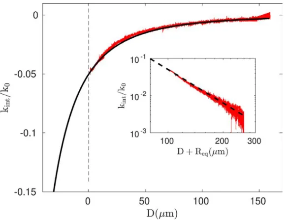
Thanks to equation (6) and (7), we plot kint/k0and βint/β0
respectively in figure 3 and 4. Interestingly, the
hydro-dynamic forces induce a variation of the in-phase parameter over a range of distance of order of 100 µm. In compar-ison, the variation of the out-of-phase component is confined within 10 µm and is close to zero beyond. The decrease
of kint was also observed with R = 8.3µm bead as shown
at short distance in figure 1. Note that dynamic AFM in
non-elastic (Newtonian) liquid generates at large distance hydrodynamic forces for which the in-phase component can be on a same order of magnitude that the one in out-of-phase. Whereas the damping increase of an oscillating sphere near a wall has already been well characterized both experimentally and numerically in the lubrication
approx-imation R > > D, the decrease of kint that accounts for the
added-mass increase as D decreases [14] has attracted less
attention.
Recently, the hydrodynamic force exerted on an oscillat-ing bead near a wall was analytically calculated for various
limit cases [19]. Three main parameters are R the bead radius,
H = R + D the distance between the bead center and the wall,
and δ =√ν/ω, the size of the boundary layer. In the
Figure 3. Evolution of kint/k0vs the distance D measured in long range FM-AFM experiments (red symbols). Comparison with the model of an oscillating bead in a liquid close to a wall (black line). Inset: verification of the power law in−3 in agreement with equation (11).
For H > > R and H > > δ corresponding to our experiments for which the flow is unsteady, the normalized perpendicular
force exerted by the fluid on the bead FN is given by:
FN =−3πR 3 4 H3 ( 5 + 3√2/Ω +√2Ω ) V⊥ −j3πR3 4 H3 ( 3/Ω + 3√2/Ω− Ω/3 −√2Ω)V⊥(10)
where Ω = R2ω/ν is the Reynolds number for a sphere and V
⊥
is the dimensionless perpendicular velocity of the bead. V⊥=
1 if the movement is purely perpendicular to the wall. In this equation, the force is normalized by ρνRV where V is the bead velocity. Rewriting this force in term of kintand βint, we obtain:
kint= ρνRω3πR 3 4 H3(3/Ω + 3 √ 2/Ω−√2Ω− Ω/3), (11) and βint= ρνR3πR 3 4 H3(5 + 3 √ 2/Ω +√2Ω). (12)
This model is compared with the experimental results in
figure3and4. The stiffness and the resonant frequency
char-acteristic of the second mode that is used in these FM-AFM experiments are measured by thermal noise with optical lever
correction: k0= 4.8 N m−1and ω0= 77.9× 10³rad s−1. Due
to the respective dimensions of the probe (R = 20.6 µm) and
of the cantilever (100× 500 µm2), the hydrodynamic forces
arise mainly from the cantilever vibration at large distance. In order to compare the results with the model, the cantilever is
assimilated to a sphere with an equivalent radius Reqand the
origin of its displacement is defined by D =−2 R. Indeed, at
D = 0, the cantilever is at a distance of 2 R due to the
pres-ence of bead probe. The experimental results are fitted by the
model with Req as the only free parameter. We found a very
good agreement between model and experiments for Req= 59
µm for the curves of kint/k0. We check that 2Reqis comprised
between the length and the width of the cantilever. The inset
of figure3shows that the experimental data follow the
power-law in (D + Req)−3in the whole range of the experimental
dis-tance as predicted by equation (11). On the other hand, the
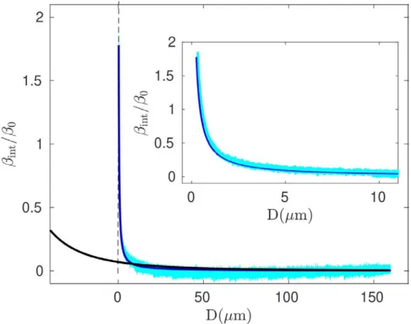
bead model points out clearly that βint/β0is small, within the
experimental noise, in agreement with the experiments at large distance. However, it cannot predict the divergence of the dis-sipation when the bead attached at the extremity of the canti-lever approaches the substrate. In this case, the dissipation is
simply given by the Reynolds formulae βint= 6πηR2/D
cal-culated in lubrication assumptions (steady flow) for the probe
of radius R and D≲ δ. The inset of figure4shows the very
good agreement between the Reynolds model and the experi-mental data, in accordance with the literature [11,15,16]. The
situation is different for kint since the Reynolds force
associ-ated with the probe has no in-phase component. As seen in
figure3no deviation from the oscillating bead model for the
cantilever is observed at short distance.
Hence, the hydrodynamic forces arise from the oscillat-ing cantilever and from the bead probe at its extremity. The
Figure 4. Evolution of βint/β0vs the distance D measured in long range FM-AFM experiments (blue symbols). Comparison with the model of an oscillating bead in a liquid close to a wall (equation (12), black line) and with the Reynolds model (blue line). Inset: comparison of experimental data of βint/β0and Reynolds model at short distance.
force on cantilever is effective at very large distance up to 200
µm and is mainly observed on the in-phase kint/k0
compon-ent. The Reynolds force on the bead probe occurs at short
distance (D≲ δ) and is only observed on the out-of-phase
βint/β0 component. In this range of distance, the dissipation
due to the force on the cantilever is negligible. We can com-pare the experimental data at D = 10µm to those obtained by numerical simulations. We measure an in-phase and out-of-phase components of the hydrodynamic load of 0.8 nN and 0.6 nN, respectively. Estimation using published numerical
simulations [13] leads to hydrodynamic forces of about 1 nN,
both for the conservative and dissipative components, in agree-ment with the experiagree-ments and the analytical model.
Equa-tions (11) and (12) can therefore be used to deduce the
equi-valent radius of the cantilever by fitting data at large distance. The long range hydrodynamic interaction due to the cantilever can then be subtracted from the total signal to infer molecu-lar interactions between the probe and the surface at short distance.
5. Conclusion
FM-AFM experiments in liquid require to take into account the hydrodynamic forces that influence measurements of the frequency shift and of the dissipation. Theoretically, we have shown that the frequency shift and the excitation amplitude are
dependent on the in-phase component kint and out-of-phase
component βint of the interaction forces including
hydro-dynamic forces. We have established the relationships which
can be used to extract kintand βintfrom the experimental raw
data. Specific FM-AFM experiments have been developed in conditions where the cantilever and the bead probe are submit-ted to hydrodynamic forces. The results were analyzed in the frame of a hydrodynamic model of one sphere oscillating near
a wall. The experiments point out that the evolution of kintwith
the distance arise from the unsteady hydrodynamic forces on the cantilever over a large range of displacement. On the other
hand, the evolution of βint is observed at short distance and
is due to the Reynolds force on the bead probe. Finally, we investigate the effects of the fluid-borne interactions (in the supplementary material) and showed that these forces do not influence the measurements in FM-AFM. This work allows us to analyze easily FM-AFM experiments in liquid in order to extract the interaction force between tip and sample. Indeed, it shows that the dissipated force between a probe and a surface can be analyzed using the Reynolds model with confidence at short distance. Moreover, the measurement of molecular
inter-action force between the probe and the surface based on kint
determination requires to subtract the effects of hydrodynamic forces on the cantilever. This can be achieved using equation
(11). This study may therefore broaden the use of FM-AFM
6. Supplementary material
See supplementary material (link) to have the details calcula-tions for FM-AFM formulae including fluid-borne forces and their effects in data of the present paper.
Acknowledgment
The authors thank the Institut Carnot Isifor which funded the RIC project and allowed us to realize this study.
ORCID iD
Philippe Tordjeman
https://orcid.org/0000-0002-6470-9081 References
[1] Israelachvili J 2011 Intermolecular and Surface Forces (Amsterdam: Elsevier)
[2] Garcia R 2010 Amplitude Modulation Atomic Force
Microscopy (Weinheim, Germany: Wiley-VCH Verlag &
Co.)
[3] Morita S, Giessibl F J, Meyer E and Wiesendanger R 2019
Noncontact Atomic Force Microscopy (Switzerland:
Springer)
[4] Dufrene Y F, Ando T, Garcia R, Alsteens D, Martinez-Martin D, Engel A, Gerber C and Mueller D J 2017 Imaging modes of atomic force microscopy for application in molecular and cell biology Nature Nanotech.12 295–307
[5] Fukuma T, Ueda Y, Yoshioka S and Asakawa H 2010 Atomic-scale distribution of water molecules at the mica-water interface visualized by three-dimensional scanning force microscopy Phys. Rev. Lett.104 016101 [6] van Lin S R, Grotz K K, Siretanu I, Schwierz N and Mugele F
2019 Ion-specific and ph-dependent hydration of mica–electrolyte interfaces Langmuir35 5737–45PMID: 30974056
[7] Ando T, Uchihashi T and Fukuma T 2008 High-speed atomic force microscopy for nano-visualization of dynamic biomolecular processes Prog. Surf. Sci.83 337–437 [8] Bar´o A M and Reifenberger R G 2012 Atomic Force
Microscopy in Liquid: Biological Applications (Germany:
Wiley-VCH Verlag & Co., Weinheim)
[9] Putman C A J, Van der Werf K O, De Grooth B G, Van Hulst N F and Greve J 1994 Tapping mode atomic force microscopy in liquid Appl. Phys. Lett.64 2454–6 [10] Kiracofe D and Raman A 2011 Quantitative force and
dissipation measurements in liquids using piezo-excited atomic force microscopy: a unifying theory
Nanotechnology22 485502
[11] Maali A and Boisgard R 2013 Precise damping and stiffness extraction in acoustic driven cantilever in liquid J. Appl.
Phys.114 144302
[12] Sader J E 1998 Frequency response of cantilever beams immersed in viscous fluids with applications to the atomic force microscope J. Appl. Phys.84 64–76
[13] Green C P and Sader J E 2005 Small amplitude oscillations of a thin beam immersed in a viscous fluid near a solid surface
Phys. Fluids17 073102
[14] Basak S, Raman A and Garimella S V 2006 Hydrodynamic loading of microcantilevers vibrating in viscous fluids J.
Appl. Phys.99 114906
[15] Maali A, Cohen-Bouhacina T and Kellay H 2008
Measurement of the slip length of water flow on graphite surface Appl. Phys. Lett.92 053101
[16] Comtet J, Nigues A, Kaiser V, Coasne B, Bocquet L and Siria A 2017 Nanoscale capillary freezing of ionic liquids confined between metallic interfaces and the role of electronic screening Nature Mat.16 634–9
[17] Suzuki K, Kobayashi K, Labuda A, Matsushige K and Yamada H 2014 Accurate formula for dissipative interaction in frequency modulation atomic force microscopy Appl. Phys.
Lett.105 233105
[18] Sader J E, Uchihashi T, Higgins M J, Farrell A, Nakayama Y and Jarvis S P 2005 Quantitative force measurements using frequency modulation atomic force microscopy?theoretical foundations Nanotechnology16 S94–S101
[19] Fouxon I and Leshansky A 2018 Fundamental solution of unsteady stokes equations and force on an oscillating sphere near a wall Phys. Rev. E98 063108