Publisher’s version / Version de l'éditeur:
Vous avez des questions? Nous pouvons vous aider. Pour communiquer directement avec un auteur, consultez la
première page de la revue dans laquelle son article a été publié afin de trouver ses coordonnées. Si vous n’arrivez pas à les repérer, communiquez avec nous à [email protected].
Questions? Contact the NRC Publications Archive team at
[email protected]. If you wish to email the authors directly, please see the first page of the publication for their contact information.
https://publications-cnrc.canada.ca/fra/droits
L’accès à ce site Web et l’utilisation de son contenu sont assujettis aux conditions présentées dans le site LISEZ CES CONDITIONS ATTENTIVEMENT AVANT D’UTILISER CE SITE WEB.
Proceedings of Acoustics '08: 29 June 2008, Paris, France, pp. 5589-5594,
2008-06-29
READ THESE TERMS AND CONDITIONS CAREFULLY BEFORE USING THIS WEBSITE.
https://nrc-publications.canada.ca/eng/copyright
NRC Publications Archive Record / Notice des Archives des publications du CNRC :
https://nrc-publications.canada.ca/eng/view/object/?id=985dd535-8f4a-4495-9b20-ec55436d877c
https://publications-cnrc.canada.ca/fra/voir/objet/?id=985dd535-8f4a-4495-9b20-ec55436d877c
NRC Publications Archive
Archives des publications du CNRC
This publication could be one of several versions: author’s original, accepted manuscript or the publisher’s version. / La version de cette publication peut être l’une des suivantes : la version prépublication de l’auteur, la version acceptée du manuscrit ou la version de l’éditeur.
Access and use of this website and the material on it are subject to the Terms and Conditions set forth at
Methods to control low frequency impact noise in wood frame
construction
Methods to control low frequency impact noise in
wood-frame construction
B. Zeitler, T. Nightingale and F. King
NRC - Institute for Research in Construction, 1200 Montreal Road, Building M-27, Ottawa,
ON K1A 0R6, Canada
[email protected]
This paper provides a preliminary report of an experimental study to confirm construction details that affect the low frequency impact sound insulation offered by platform wood frame constructions. The paper shows that ceiling mounting, floor stiffness, and floor toppings can be effective methods to improve impact sound insulation from the “bang machine” heavy impact source. Additionally, the paper shows that in the frequency range where the single number ratings are controlled direct transmission dominates but flanking is sufficiently important to affect the apparent impact sound insulation to the room below. Measurements of flanking transmission to horizontally adjacent rooms indicate that the floor-floor path can generate impact levels comparable to the direct path to the vertically adjacent room below. As such, good design should consider transmission to horizontally adjacent rooms.
1
Introduction
This paper reports preliminary experimental results from a project to identify construction details that affect the ability of wood framed floors and the supporting structures to protect against low frequency impact noise. Many of the parameters investigated here were identified in an earlier theoretical study [1] but needed experimental confirmation. In the experimental study systematic changes were made to a reference assembly to assess the change in impact sound pressure level for direct and flanking transmission involving the supporting structures. The assemblies were evaluated using three standardized impact sources: ISO “tapping machine” (ISO 140-6), “impact ball” (JIS A 1418-2, ISO 140-11), and “bang machine” (JIS A 1418-1418-2, KS F 2810-2). Because of limited space this paper reports only results for the bang machine heavy impactor.
While the bang machine is used in both Japan and Korea and the relevant test methods are virtually identical, the single number metrics used in the countries differ significantly (JIS A 1419-2, KS F 2863-2). This has been discussed elsewhere and a rule-of-thumb conversion has been suggested [2] for heavy concrete constructions.
2
Construction
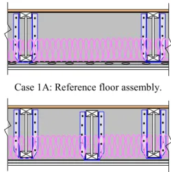
This paper considers the five platform wood frame constructions shown in Figure 1. The is one reference assembly (Case 1A) and four variants (Cases 1B, 1C, 1E and 1F). (Data for Case 1D are not available at this time). All assemblies were installed in the NRC-IRC Flanking Transmission Facility [3]. The figure shows two variants assessed treatments to the mounting of the gypsum board ceiling (Cases 1B and 1C), one assessed the stiffening the floor (Case 1E) and one assessed treatment to the exposed floor surface in the form of floor topping placed on an interlayer (Case 1F). All the floors had a sub-floor of 19 mm oriented strand board (OSB) screwed to the top of the 305 mm wood-I joists, 150 mm thick insulation between the joists, and a double layer of 16 mm gypsum board supported below the joists on resilient metal channels. In each case the wall/floor junction included suitable elements to block fire spread via the floor cavity, and the OSB sub-floor sheathing was continuous across the wall/floor junction.
The walls as shown in Figure 2 each had one row of 38 x 89 mm wood studs, with 2 layers of 16 mm gypsum board screwed directly to one side, and one layer of 16 mm gypsum board mounted on the other side using resilient metal channels. The facility has eight rooms in total – four on each of two levels.
Case 1A: Reference floor assembly.
Case 1B: Reference assembly with separate ceiling joists to isolate the gypsum board ceiling.
Case 1C: Reference assembly with separate ceiling joists and resilient channels to further isolate the gypsum board
ceiling.
Case 1E: Reference assembly with number of floor joists doubled (joists spacing halved) and blocking and strapping
added. Gypsum board ceiling is mounted on resilient channels.
Case 1F: Topping with interlayer applied to the Case 1E assembly.
Figure 1: Floor ceiling assemblies used in this study. Acoustics 08 Paris
Initially, the Case 1A reference assembly was installed. Subsequently, one floor-ceiling assembly, the floor in the northwest (indicated by NW in Figure 2), was systematically varied to create the four variants. The floors in all other rooms were unchanged throughout the experimental series.
NW NE
SW SE
Figure 2: Floor ceiling assemblies used in this study. Methods [3] developed in previous NRC-IRC projects and ISO 10848 were employed to isolate the various flanking transmission paths to the vertically adjoining room (direct and floor-wall paths), and horizontally adjoining rooms (floor-floor flanking path). Sound insulation estimates are assigned to the direct path through the floor ceiling assembly, as well as receive room flanking paths when the walls have two layers of direct-attached gypsum board. The sum of these paths is the apparent sound insulation – the quantity used by performance-based building codes and quality indication systems.
Before and periodically during the experimental series, the bang machine was calibrated using a RION PF-10 force plate and the tire pressure was adjusted as required.
3
Results for Direct Transmission
This section examines direct transmission to the vertically adjoining room below – flanking paths involving the supporting walls have been suppressed.
3.1 Effect of repeated impacts
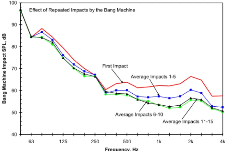
It has been suggested that the force applied by the bang machine is sufficient to damage wood joist floors [4]. To verify this the bang machine was placed at the centre of the newly constructed Case 1A wood joist floor and the peak impact sound pressure level measured in the room immediately below for each of 15 consecutive impacts. Any averaging was performed using the measured data for each impact.
Figure 3 shows that for 80 Hz and above, the first impact generates the greatest sound pressure level, and that subsequent impacts produce a lower sound pressure level. After about 6-10 impacts the average has stabilized. The effect is greatest for the range 315 – 4000 Hz and appears to generally increase with increasing frequency. In this range the impact level for the first impact is almost 10 dB greater than the stabilized level achieved after many repeated impacts. It is tempting to argue that this range is
not very important because the single number ratings in Japan and Korea extend from the 63 Hz octave band to the 500 Hz octave band (i.e., 50 to 630 Hz when expressed using third-octave bands). However in the range where the single number ratings are determined the maximum effect was 5 dB. 40 50 60 70 80 90 100 63 125 250 500 1k 2k 4k Frequency, Hz B a n g Mach in e I m p act S P L , d B
Effect of Repeated Impacts by the Bang Machine
First Impact
Average Impacts 1-5
Average Impacts 6-10
Average Impacts 11-15
Figure 3: Measured peak impact sound pressure level in the room immediately below the bang machine. Averages are
of the RMS pressure level for each impact.
The figure clearly shows that during the course of the impact measurement the bang machine physically alters the vibro-acoustic response of the wood joists floor. The effect is irreversible and is highly suggestive that the response is non-linear to the first few impacts. The cause of this is not known but an NRC-IRC study is examining the force exposure level at which the vibro-acoustic response (for direct and flanking transmission) ceases to be linear (and the transmitted sound power does not vary proportionally to the injected power by the impact source).
3.2 Effect of ceiling treatments
In this section the effectiveness of changing the mounting of the gypsum board ceiling is investigated.
In Case 1B there are separate floor and ceiling joists. The floor joists support the OSB subfloor and separate ceiling joists support the directly attached gypsum board ceiling. This effectively eliminates the structure borne path from the OSB subfloor (impacted by the bang machine) and the gypsum board ceiling (which radiates into the receive room immediately below). In theory, the only purely structure borne path that remains is via the solid perimeter joist (rimboard) where each end of the floor and ceiling joists are supported by joist hangers, as shown in Figure 1.
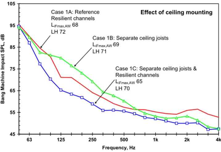
Figure 4 shows that relative to the reference floor with resiliently mounted ceiling, using ceiling joists is beneficial in the low (50-80 Hz) and the high (800-4000 Hz) frequencies. However, in the midrange (125-630 Hz) the separate ceiling joists are not beneficial and increase the peak impact levels by 5 to 9 dB over several bands. Interestingly, the Japanese single number rating (Li,Fmax,r,H
which is commonly referred to as LH) suggests that using ceiling joists will be marginally better – the single number rating is reduced – while Korean rating (L’i,Fmax,AW,H)
suggests that ceiling joists will be marginally worse. This is due to differences in the fitting procedures for the
reference contour of the single number rating. The Japanese rating is controlled by results in the 63 Hz octave band and responds to the slight level reduction here, whereas the Korean rating controlled by the 125 Hz octave band reflects the level increase in this band.
45 55 65 75 85 95 105 63 125 250 500 1k 2k 4k Frequency, Hz B a n g Mach in e Im p act SPL , d B
Case 1A: Reference Resilient channels LiFmax,AW 68
LH 72
Case 1B: Separate ceiling joists LiFmax,AW 69
LH 71
Case 1C: Separate ceiling joists & Resilient channels
LiFmax,AW 65
LH 70
Effect of ceiling mounting
Figure 4: Measured peak impact sound pressure level in the room immediately below for the Case 1A reference assembly, Case 1B when there were separate ceiling joists
and directly attached gypsum board, and Case 1C where there were separate ceiling joists and a resiliently mounted
gypsum board ceiling.
Figure 4 also shows the benefit of Case 1C where resilient channels are placed between the ceiling joists and the gypsum board. Adding resilient channels causes a profound reduction in the impact sound pressure level in the range 80-800 Hz relative to Case 1B. Most bands in this range experience a 10 dB reduction, or more. It is tempting to attribute this to enhanced vibration isolation caused by the resilient channels, but this would be an oversimplification because resilient channels reduce the both structure borne vibration transmission to gypsum board as well as the efficiency with which the gypsum board radiates [5]. When gypsum board is directly attached to the (floor or ceiling) joists the wavenumbers in the gypsum board are significantly lowered [6] relative to the resiliently mounted gypsum board, and the critical frequency shifts from about 2000 Hz to closer to 125 Hz. This apparent shift the critical frequency of the gypsum board ceiling allows for significantly more transmission in the range 125 to 630 Hz. Above about 630 Hz both the first mode of the gypsum board sub-panels cut on and the gypsum board appears point-connected to the joists. Because of these the joists have minimal effect and the radiation efficiency is similar to that of the resiliently mounted gypsum board ceiling and the impact sound pressure levels for the Case 1B and 1C are similar above about 630 Hz.
3.3 Effect of framing treatments
A companion paper [7] investigates the interaction between the impedances of the source and floor to modify the power injected by an impact source so only a qualitative discussion will be given here. There are three ways to minimize the power injected by an impact source. They are 1.) minimize the blocked force (force exposure level) of the source, 2.) modify the impedance of the floor so that the real part of its impedance is as small as possible, 3.) modify
the floor so that modulus of the of the sum of the floor and source impedance is as large as possible. Since we are using a standardized impact source its properties (impedance and blocked force) cannot be changed. Thus the general approach is to modify the floor so that it remains stiffness controlled in the low frequencies where the bang machine is also stiffness controlled. Increasing the mass, as we will see in the next section can be very effective, too.
There are many ways to significantly stiffen a joist floor [1] and Case 1E did not employ all these methods. In Case 1E the spacing of the floor joists was halved (so the number of joists was doubled) which stiffens the floor significantly in the direction parallel to the joists but offers little increase in the direction perpendicular to the joists. To increase the stiffness in the direction perpendicular to the joists rows of solid blocking and strapping were added every 900 mm on center. Like Case 1A the ceiling was mounted on resilient channels.
Figure 5 shows the impact sound pressure levels for the Case 1A reference assembly and the Case 1E stiffened floor. From the figure it is clear that the treatments to stiffen the floor significantly reduce the impact levels. The treatment was most effective in the range 80-200 Hz and translated into a 4 dB level reduction when assessed using the Korean rating, and a 3 dB reduction when using the Japanese rating. Stiffening the floor can be an effective method to reduce the power injected and hence reduce direct transmission. However, it must be recognized that if the added stiffening elements cause increased structure borne transmission through the floor then the benefit of the reduction in injected power will not be fully realized.
40 50 60 70 80 90 100 63 125 250 500 1k 2k 4k Frequency, Hz B a n g Mach in e Im p act SPL , d B
Case 1A: Reference LiFmax,AW 68
LH 72
Case 1E: Stiffened floor LiFmax,AW 64
LH 69
Effect of stiffening the floor
Figure 5: Measured peak impact sound pressure level in the room immediately below for the Case 1A reference
assembly and the Case 1E stiffened floor.
3.4 Effect of a floor topping
Case 1F was formed by placing a topping consisting of two layers of 12.5 mm thick gypsum cellulose board panels and a 10 mm mineral wool interlayer on the Case 1E stiffened floor. The topping had a surface density of about 24 kg/m2. Figure 6 shows that adding a floor topping to the stiffened floor results in a very significant reduction in impact levels over the entire frequency range, (compare Cases 1E and 1F). The exception is 160 Hz where the topping is Acoustics 08 Paris
ineffective. This requires investigation but is likely due to a resonance involving the stiffness of the interlayer. The Case 1A reference floor is given to show that by stiffening the floor and applying a floor topping, heavy impact levels can be reduced by 10 dB over the frequency range 50-4000 Hz. This is reflected by the significant improvement in the single number ratings.
35 45 55 65 75 85 95 105 63 125 250 500 1k 2k 4k Frequency, Hz Ban g M ach in e I m p act S P L , d B
Case 1A: Reference LiFmax,AW 68
LH 72
Case 1E: Stiffened floor LiFmax,AW 64
LH 69
Case 1F: Topping applied to the stiffened floor LiFmax,AW 56
LH 62
Effect of a floor topping
Figure 6: Measured peak impact sound pressure level in the room immediately below for the Case 1A reference assembly, the Case 1E stiffened floor, and the Case 1F
stiffened floor with the topping.
4
Results for Flanking and Apparent
Transmission
The previous section examined the effect of various floor treatments to control direct transmission through the nominally separating floor-ceiling assembly. This section examines flanking transmission; the floor-wall path to the room below in the case of vertically adjoining rooms, and the floor-floor path in the case of horizontally adjoining rooms.
We begin by examining flanking between vertically and horizontally adjoining rooms for the Case 1E construction having the stiffened floor. It has been shown for light impact and airborne sources [3] that joist orientation (which determines if the junction is bearing or non-bearing) can significantly affect flanking through this junction, but has not be verified for heavy impact sources where the frequency range extends below 100 Hz.
For the Case 1E construction, Figure 7 shows the floor-wall flanking path to the vertically adjoining room, and the floor-floor path to the horizontally adjoining room when the joists are perpendicular to the junction (and supported by the bearing wall). Also shown for comparison is the estimate for direct transmission.
It is interesting to note that for vertically adjoining rooms of Case 1E the impact sound pressure level due to a single floor-wall path involving the load bearing wall is typically 10 dB lower than the direct path. A single floor-wall path is insignificant. Perhaps of more interest is the comparison between the floor-floor and floor-wall flanking paths. The floor-floor path (to the horizontally adjoining room) is considerably stronger than the floor-wall path (to the vertically adjoining room below) and is comparable to the
direct path (to the room below). This strongly suggests that good design must also consider the impact transmission between horizontally adjoining rooms.
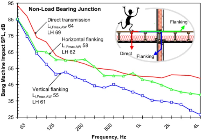
Figure 8 shows the same Case 1E paths except now the joists are parallel to the flanking junction. By comparing Figure 7 and Figure 8 one can assess the effect of joist orientation on the flanking between vertically and horizontally adjoining rooms. It is clear that the most noticeable difference occurs below about 100 Hz. With the joists parallel to the junction flanking there is significantly more flanking for both the floor-floor and floor-wall paths.
25 35 45 55 65 75 85 95 63 125 250 500 1k 2k 4k Frequency, Hz Ban g M ach in e Imp act S P L , d B Direct transmission Li,Fmax,AW 64 LH 69 Vertical flanking Li,Fmax,AW 48 LH 53 Direct Flanking Flanking Horizontal flanking Li,Fmax,AW 57 LH 58
Load Bearing Junction
Figure 7: Measured peak impact sound pressure levels for the Case 1E construction. Shown are direct transmission, a
single floor-wall flanking path involving a load-bearing wall in the room below, and the floor-floor flanking path to
the horizontally adjoining room.
25 35 45 55 65 75 85 95 63 125 250 500 1k 2k 4k Frequency, Hz Ban g M ach in e I m p act S P L , d B
Non-Load Bearing Junction
Direct Flanking Flanking Direct transmission Li,Fmax,AW 64 LH 69 Vertical flanking Li,Fmax,AW 55 LH 61 Horizontal flanking Li,Fmax,AW 58 LH 62
Figure 8: Measured peak impact sound pressure levels for the Case 1E construction. Shown are direct transmission, a single floor-wall flanking path involving a non-load bearing wall in the room below, and the floor-floor flanking path to
the horizontally adjoining room.
5
Discussion and Conclusions
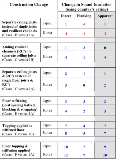
Table 1 below provides a convenient summary of the change in heavy impact sound insulation for vertically adjoining rooms from the bang machine due to the construction changes considered in this paper.
The first thing to note is the effectiveness of the various treatments is weighted differently by the single number rating schemes of each country. Most often the Korean rating scheme indicates a greater improvement. The exception is Case 1B versus Case 1A where the Korean rating scheme suggested a reduction in sound insulation and the Japanese rating scheme suggested the opposite.
Construction Change Change in Sound Insulation (using country’s rating)
Direct Flanking Apparent Separate ceiling joists
instead of single joists and resilient channels
(Cases 1B versus 1A)
Japan 1 -1 1
Korea -1 -1 -2
Adding resilient
channels (RC’s) to separate ceiling joists
(Cases 1C versus 1B)
Japan 1 2 0
Korea 4 1 4
Separate ceiling joists
& RC’s instead of single floor joists & RC’s
(Cases 1C versus 1A)
Japan 2 1 1
Korea 3 0 2
Floor stiffening
(joist spacing halved, blocking & strapping)
(Cases 1E versus 1A)
Japan 3 3 2
Korea 4 2 3
Topping applied to
stiffened floor
(Cases 1F versus 1E)
Japan 7 4 7
Korea 8 5 7
Floor topping &
stiffening applied
(Cases 1F versus 1A)
Japan 10 7 9
Korea 12 7 10
Table 1: Changes in heavy impact sound insulation for the indicated transmission paths to the vertically adjacent room below expressed using the single number rating scheme for
each country (Li,Fmax,r,H for Japan, and L’i,Fmax,AW,H for
Korea). A positive number indicates an increase in sound insulation (and a reduction in impact levels). The apparent sound insulation is the sum of the direct paths and the four floor-wall flanking paths when each wall has two layers of
direct attached gypsum board.
The table shows that the most effective ceiling mounting treatment is to use separate ceiling joists with resilient channels. (In this case the resilient channels ensure the radiation efficiency of the gypsum board ceiling is not enhanced by the direct mounting to the joists).
Stiffening the floor while maintaining a resiliently mounted gypsum board ceiling is an effective method to improve the heavy impact sound insulation. It is slightly more effective than using separate ceiling joists with resilient channels. Adding a topping had the biggest incremental effect and is probably the single most important treatment that can be used to control heavy impact sound. Relative to the untreated reference floor the combination of the floor topping and the stiffening treatments resulted in about an 11 dB increase in the heavy impact sound insulation.
The table shows that treatments affect direct and flanking transmission differently and that the different single number rating schemes report different magnitudes. Typically, the treatments were less effective for the floor-wall flanking paths than the direct path through the floor/ceiling assembly. While flanking transmission does not dominate, it does affect the single number heavy impact rating for the apparent impact sound insulation.
The experimental study confirmed the construction details that affect the transmission of low frequency impact sound from the bang machine heavy impact source. Since the assemblies considered were not optimised it should be possible to achieve greater improvements and develop wood frame assemblies that provide good low frequency impact sound insulation.
Acknowledgments
The support of the Council of Forest Industries through the Canada Wood and Forestry Innovation Initiative Programs is gratefully acknowledged.
References
[1] Nightingale, Trevor; Bosmans, Ivan, “Two modelling approaches for periodic rib-stiffened plates typical of floor assemblies,” Proceedings of 14th International Congress on Sound and Vibration, Cairns Australia, July 2007, paper number 488.
[2] Jang, Gil-Soo, Proceedings of the 10th International Conference on Building Acoustics, Chonnam University, April 2004. (In Korean).
[3] Nightingale, T.R.T.; Quirt, J.D.; King, F.; Halliwell, R.E. Flanking Transmission in Multi-Family Dwellings: Phase IV, Research Report, Institute for Research in Construction, National Research Council Canada, 218, pp.
425, March 01, 2006 (
http://irc.nrc-cnrc.gc.ca/pubs/rr/rr218/).
[4] Jin Yong Jeon, Jong Kwan, Ryu, Joeng Ho Jeong, Hideki Tachibana, “Review of the impact ball in evaluating floor impact sound”, Acta Acustica united with Acustica, Vol. 92 (2006) pp. 777-786.
[5] Mayr, A.,; Nightingale, T.R.T., "On transmission of structure borne power from wood studs to gypsum board mounted on resilient metal channels - Part 2: Some simplifications for modelling," Canadian Acoustics, 32, (3), September, Canadian Acoustical Association Conference (Ottawa, Ontario, October 06, 2004), pp. 166-167,
September 01, 2004
http://irc.nrc-cnrc.gc.ca/pubs/fulltext/nrcc45338/
[6] Nightingale, T.R.T.; Halliwell, R.E.; Pernica, G. "Estimating in-situ material properties of a wood joist floor: Part 1 - Measurements of the real part of bending wavenumber and modulus of elasticity," Building Acoustics, 11, September, pp. 1-27, September 01, 2004 [7] Zeitler, B., Nightingale, T.R.T., “Impedances of standard impact sources and their effect on impact sound pressure level of floors,” Proceedings Acoustics08.