Publisher’s version / Version de l'éditeur:
Scientific Reports, 7, 1, 2017-08-29
READ THESE TERMS AND CONDITIONS CAREFULLY BEFORE USING THIS WEBSITE. https://nrc-publications.canada.ca/eng/copyright
Vous avez des questions? Nous pouvons vous aider. Pour communiquer directement avec un auteur, consultez la première page de la revue dans laquelle son article a été publié afin de trouver ses coordonnées. Si vous n’arrivez pas à les repérer, communiquez avec nous à PublicationsArchive-ArchivesPublications@nrc-cnrc.gc.ca.
Questions? Contact the NRC Publications Archive team at
PublicationsArchive-ArchivesPublications@nrc-cnrc.gc.ca. If you wish to email the authors directly, please see the first page of the publication for their contact information.
NRC Publications Archive
Archives des publications du CNRC
This publication could be one of several versions: author’s original, accepted manuscript or the publisher’s version. / La version de cette publication peut être l’une des suivantes : la version prépublication de l’auteur, la version acceptée du manuscrit ou la version de l’éditeur.
For the publisher’s version, please access the DOI link below./ Pour consulter la version de l’éditeur, utilisez le lien DOI ci-dessous.
https://doi.org/10.1038/s41598-017-09323-w
Access and use of this website and the material on it are subject to the Terms and Conditions set forth at
Response to alternating electric fields of tubulin dimers and
microtubule ensembles in electrolytic solutions
Santelices, Iara B.; Friesen, Douglas E.; Bell, Clayton; Hough, Cameron M.;
Xiao, Jack; Kalra, Aarat; Kar, Piyush; Freedman, Holly; Rezania, Vahid;
Lewis, John D.; Shankar, Karthik; Tuszynski, Jack A.
https://publications-cnrc.canada.ca/fra/droits
L’accès à ce site Web et l’utilisation de son contenu sont assujettis aux conditions présentées dans le site LISEZ CES CONDITIONS ATTENTIVEMENT AVANT D’UTILISER CE SITE WEB.
NRC Publications Record / Notice d'Archives des publications de CNRC:
https://nrc-publications.canada.ca/eng/view/object/?id=a390cd76-b16c-4ffd-abab-a0c0e64f3584
https://publications-cnrc.canada.ca/fra/voir/objet/?id=a390cd76-b16c-4ffd-abab-a0c0e64f3584
Fields of Tubulin Dimers and
Microtubule Ensembles in
Electrolytic Solutions
Iara B. Santelices
,, Douglas E. Friesen , Clayton Bell , Cameron M. Hough
,, Jack Xiao
,,
Aarat Kalra
, ,, Piyush Kar , Holly Freedman , Vahid Rezania , John D. Lewis , Karthik
Shankar
,& Jack A. Tuszynski
,Microtubules (MTs), which are cylindrical protein ilaments that play crucial roles in eukaryotic cell functions, have been implicated in electrical signalling as biological nanowires. We report on the small-signal AC (“alternating current”) conductance of electrolytic solutions containing MTs and tubulin dimers, using a microelectrode system. We ind that MTs ( nM tubulin) in a -fold diluted BRB electrolyte increase solution conductance by % at kHz, and this efect is directly proportional to the concentration of MTs in solution. The frequency response of MT-containing electrolytes exhibits a concentration-independent peak in the conductance spectrum at kHz ( kHz FWHM that decreases linearly with MT concentration), which appears to be an intrinsic property of MT ensembles in aqueous environments. Conversely, tubulin dimers ( nM) decrease solution conductance by % at
kHz under similar conditions. We attribute these efects primarily to changes in the mobility of ionic species due to counter-ion condensation efects, and changes in the solvent structure and solvation dynamics. These results provide insight into MTs’ ability to modulate the conductance of aqueous electrolytes, which in turn, has signiicant implications for biological information processing, especially in neurons, and for intracellular electrical communication in general.
Microtubules (MTs) are hollow cylindrical protein polymers composed of α- and β- tubulin hetero-dimers1.
hese dimers spontaneously self-assemble longitudinally to form protoilaments, and 13 protoilaments constitute a microtubule, resulting in a helical arrangement of tubulin heterodimers. With a diameter of 25 nm, MTs form a rigid structure integral to the cytoskeleton of each eukaryotic cell2. heir primary roles include providing a rigid
structure to the cell and acting as the wires to pull chromatids apart in mitosis. Also, motor proteins use MTs as a track, with kinesins moving anterograde, towards the positively charged end, and dyneins moving retrograde, towards the negatively charged end of MTs3, 4. Kinesin and dyneins play a crucial role in endocytosis and
exocy-tosis, moving organelles, along with chromosome segregation during mitosis and meiosis.
MTs have also been implicated in intra-cellular signalling and information processing, as tubulin has a large dipole moment, and consequently MTs have a large cumulative dipole moment, which provides electrostatic polarity and hence functional directionality5. Tubulin dimers which form the MT structure have highly
elec-tronegative C-termini, which attract positive counterions, providing a potential mechanism for the observed ampliication of ionic signalling6–8. It has been hypothesized that MTs are involved in information processing via
conductivity efects in neurons as well as in an organism-wide matrix of connected biological wires9, 10. As well,
exposure to alternating electric ields between 100–300 kHz of strength ~1–2.5 V/cm have been shown to arrest Department of Electrical & Computer Engineering, University of Alberta, Edmonton, Alberta, T G H , Canada. Department of Oncology, University of Alberta, Edmonton, Alberta, T G Z , Canada. NRC National Institute for Nanotechnology, Edmonton, Alberta, T G M , Canada. Department of Physics, University of Alberta, Edmonton, Alberta, T G E , Canada. Department of Medical Physics, Cross Cancer Institute, Edmonton, Alberta, T G Z , Canada. Department of Medical Microbiology and Immunology, University of Alberta, Edmonton, Alberta, T G E , Canada. Department of Physical Sciences, MacEwan University, Edmonton, Alberta, T J S , Canada. Correspondence and requests for materials should be addressed to K.S. (email: kshankar@ualberta.ca) or J.A.T. (email: jackt@ualberta.ca)
Received: 17 January 2017 Accepted: 20 July 2017 Published: xx xx xxxx
www.nature.com/scientificreports/
cell mitosis11 and have led to an FDA approved treatment of glioblastoma multiforme12, with these ield efects
on MTs being hypothesized as a primary mechanism of action11, 13, 14. his latter development provides strong
motivation to elucidate the response of solutions with MTs to externally applied AC electric ields.
Potential biological efects of alternating electric ields in the range of hundreds of kHz have recently been reviewed14. In particular, dielectrophoretic forces could develop in the presence of an applied ield on the order
of hundreds of kHz as a result of inhomogeneity in the intracellular electric ield and interfere with the proper alignment of the mitotic spindle. Moreover, dipole moment changes in proteins can be induced in the directions of oscillating electromagnetic ields using driving frequencies relevant to protein dipolar relaxation times15. One
study probed the efect of 10 Hz to 3 kHz AC stimuli on cells transfected with K + channels and on control cells, and found that both kinds of cells oscillated in phase with the driving frequency in the direction normal to the membrane up to frequencies of 1.5 kHz. Because of the sensitivity to the membrane potential and larger amplitude of movement of the transfected cells compared to the wild-type cells, it was hypothesized that the movements of transfected cells were caused by oscillations in the positions of voltage sensor regions of the channels16, 17.
Furthermore, there exist controversial claims such as the suggestion that MTs are 1000x more conductive than a single tubulin building block due to the interstitial water channel within the MT18. hus, additional studies of
the electrical properties of MTs are warranted, which is one of the reasons for undertaking the research presented in this paper.
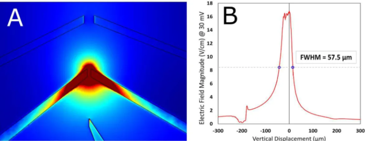
In this study, we designed two platinum microelectrodes, 14 µm apart (see Fig. 1), and performed electri-cal characterization of solutions with various concentrations of MTs made of 42.4 nM, 84.8 nM and 212 nM of tubulin, and tubulin dimers, at a range of AC frequencies between 1 kHz and 10 MHz, in a low ionic strength solution. he electric ield distribution and relative ield strength for the microelectrode geometry employed, are shown in Fig. 2. Microelectrodes ofer outstanding performance in eliminating parasitic voltage drops and difusion efects, and achieving fast equilibration times due to which we utilized them to obtain the conductiv-ity spectra of electrolytic solutions containing tubulin dimers and MT ensembles19, 20. he maximum electric
ield applied was 25 V cm−1, for which Faradaic charge injection efects can be ignored in the frequency range studied21. Microluidic impedance spectroscopy, such as used in this work, ofers a much higher sensitivity than
AC electrokinetic techniques previously used to study the conductivity of MT solutions8, 22. A schematic of the
cross-section of the low-cell is provided in Fig. S1. he goal of this study was to quantify the efects of MTs on conductance of solutions, and uncover an optimal protocol to observe MT electrical efects in bufer solutions approaching physiological-like conditions at relevant values of temperature, pH, and ionic concentrations. hese results can then be extended to directly study the electrical ampliication efects of MTs, which has hitherto been extremely challenging10.
Results
MTs are only stable in aqueous electrolytes with a high concentration of solvated ions. MTs spontaneously dis-assemble in timescales of the order of minutes, in non-aqueous electrolytes and in low ionic strength aqueous electrolytes23. he contribution of MTs to the conductivity of high ionic strength bufers is diicult to extract
due to the high overall ionic conductance of such electrolytes and the existence of numerous parasitic efects. At the same time, when the ionic strength is decreased below a threshold value in order to uncover the intrinsic Figure 1. (A) Electrode low cell design used in this study (B) Zoomed-in view of low cell where 5 electrodes converge (C) MTs imaged using Zeiss LSM 710 confocal microscope equipped with a 40x objective; excitation wavelength was 592 nm ater MT-containing electrolyte was introduced into low cell; image focused at the top of the low cell above the electrodes, which are not visible (D) Same as (C) but image focused on electrode plane (E) 3D model of the electrode low cell in (A) and (B). 45/10 nm Pt/Ti electrodes (yellow) are printed on the surface of a 1.1 mm thick borosilicate wafer (gray). A 0.15 mm coverslip (white) is placed on top of two pieces of double-sided tape (blue) to create a low cell with a channel gap of 50 µm width. here is a 14 µm gap between electrodes 2 and 4 which have a length of 30 µm.
conductivity of MTs, the MTs disassemble23. hese limitations have stymied direct measurements of MT
con-ductance. We determined an optimized protocol that allowed us to overcome the aforementioned competing efects and directly measure the MT contribution to the overall conductance. Figure 3 shows that Taxol-stabilized MTs are stable for at least an hour in the 20-times diluted stock ‘bufer’ electrolyte (BRB4) used by us. Exposure to alternating ields allowed us to understand the frequency dependence of the conductivity and the use of small-signal impedance measurements eliminated the efect of local heating and electrode polarization efects observed at high bias. Previous reports have used poly-L-lysine (PLL) to anchor MTs to a substrate (typically silicon dioxide), in which case the electrostatic interactions of the anchored MTs with the PLL substrate might change the solvation dynamics of the electrolyte ions and MTs23, 24. For this reason, MTs were not anchored to the
substrate in our studies.
Our ‘stock’ bufer solution (BRB80) consisted of 80 mM PIPES (pH 6.9), 2 mM MgCl2 and 0.5 mM EGTA. BRB80 is a very typical high ionic strength electrolyte in which the MTs are stable for weeks due to which it has been used to conduct investigations of microtubule behavior25, 26. In order to distinguish the conductivity
con-tribution of MTs while still maintaining suicient structural stability of the MTs to enable imaging and electrical measurements, we used an electrolyte we call BRB4 consisting of BRB80 diluted 20 times with milli-Q water. Figure 4 presents the small signal conductance data for electrolytes containing varying concentrations of MTs. Figure 4A shows that MT solutions have a higher conductance than BRB4 bufer alone. As the concentration of MTs increases, so does the conductance of the electrolytes containing them. he conductance increases in the 1 kHz −110 kHz frequency range for BRB4 and BRB4-MT solutions. For frequencies higher than 100 kHz, the conductance begins to decrease for BRB4 and BRB4-MT solutions. In Fig. 4B, the percent increase in conduct-ance for the BRB4-MT solutions compared to BRB4 solution is plotted. As the concentration of MTs increases, the percent increase in conductance follows suit linearly (Fig. S2). he % MT conductance increases slightly from 1 kHz to 100 kHz, and this increase is most pronounced for MTs made using 212 nM of tubulin. Beyond 100 kHz, the % MT conductance begins to decrease slightly for 42.4 nM, 84.8 nM and 212 nM, and this decline is seen most obviously for MTs made from 212 nM of tubulin. In Fig. 4C, it is seen that BRB4 solution has a higher conduct-ance than when free tubulin is added to the solution. he conductconduct-ance increases from 1 kHz to around 60 kHz for both the BRB4 solution containing colchicine and unpolymerized tubulin, following which the conductance decreases for frequencies higher than 60 kHz. In Fig. 4D, the percent increase in conductance for BRB4-MT1x (MTs made from 42.4 nM of tubulin) and BRB4-T1x (un-polymerized 42.4 nM tubulin) are each compared to BRB4 (bufer) solution. he % conductance increase from MTs made from 42.4 nM of tubulin is similar to the % decrease that 42.4 nM of un-polymerized tubulin results in. From 100 kHz – 1 MHz, both the BRB4-MT1x and BRB4-T1x solutions have their % conductance diferences reduced in absolute value.
Upon adding higher amounts of unpolymerized tubulin to BRB4, the electrolyte conductance experiences a net increase as shown in Fig. 4E. Figure 4E compares the percent increase in conductance for BRB4 solutions with MTs made from 212 nM of tubulin to those containing 212 nM of un-polymerized tubulin each compared to BRB4 solution. he % conductance increase is greater for BRB4-MT5x than BRB4-T5x. From 100 kHz to 1 MHz, the % conductance increase declines for BRB4-MT5x, but still continues to increase from BRB4-T5. he diference in conductance at 100 kHz between BRB4-T1x and BRB4-C is statistically signiicant (p = 7E-4). he diference in conductance between BRB4 and MT solutions is also statistically signiicant (BRB4-MT1x, p = 4E-4, BRB4-MT2x, p = 3E-4, BRB4-MT5x, p = 2E-7). As well, the diference in conductance between BRB4-MT1x and BRB4-MT5x is signiicant (p = 2E-4). Furthermore, the diference between BRB4-MT1x and BRB4-T1x is signiicant (p = 4E-4). Figure 5 is a histogram plot of the absolute conductance values of the diferent electro-lytes studied, summarizing the concentration-dependent electrical behavior of the tubulin dimer-containing and MT-containing electrolytes in relation to each other and to the low ionic strength bufer (BRB4) electrolyte.
Electric current in a solution of MTs and bufer is modeled as a circuit with distinct parallel resistive elements through which charges can low. In this case, the total conductance Stot is:
Figure 2. (A) COMSOL simulations of the electric ield magnitude for a voltage applied between electrodes 2 and 4 (see Fig. 1E) (B) Plot of ield magnitude along vertical central line between electrodes; FWHM = 57.5 µm.
www.nature.com/scientificreports/
= + ⇒ = + S S S S S S S 1 (1) tot B MT tot B MT Bwhere SB is the conductance due to the bufer and SMT is the conductance due to the MTs. To determine the frequency-dependent characteristics of MT conductance, we assume that the ratio SMT/SB can be expressed as a function that depends only on frequency f:
= + ⇒ = +
S S S S
S 1 F f( ) (2)
tot B MT tot B
To characterize the frequency dependence of the observed conductance shown in Fig. 4, we it the data with a Voigt lineshape. his function is a convolution of a Gaussian and Lorentzian proile:
= ⊗
F f( ) G f( ) L f( ) (3)
Figure 3. Taxol stabilized MTs remain stable for up to 60 minutes when transferred to a BRB4 bufer. MTs imaged (a) 10 minutes ater transfer, (b) 30 minutes ater transfer and (c) 60 minutes post-transfer.
where G(f) is of the form − − A expG f C B ( ) 2 G G 2
2 , and L(f) is of the form
− + AL B f C B ( / 2) ( ) ( / 2) L L L 2
2 2, where A, B, and C are the
amplitudes, widths, and central frequencies (respectively), and subscripts indicate Gaussian or Lorentzian func-tion parameters. he convolufunc-tion of these lineshapes incorporates separate broadening mechanisms that are potentially signiicant in MT-induced conductance variation: he Gaussian proile describes heterogeneous efects such as (1) Doppler broadening that could arise due to the distribution of velocities of the charged species contributing to the measured currents, and (2) the distribution of MT lengths along which charged species travel. Conversely, the Lorentzian describes homogeneous broadening mechanisms such as collisional losses due to interacting Coulomb ields. he choice of the Voigt lineshape allows for natural interpretations of amplitude A, width B (FWHM), and central frequency C that can be related to the observed conductance behaviours of MTs. here is an additional background ofset parameter that represents a frequency-independent increase of conduct-ance due to the addition of microtubules. Optimal parameters were determined by weighted least-squares Figure 4. (A) Conductance of the BRB4 Bufer (n = 69), BRB4-MT1x (n = 21), BRB4-MT2x (n = 15),
and BRB4-MT5x (n = 18) are plotted against frequency (mean, n is the number of trials). Conductance increases with increasing concentration of MTs. (B) Mean %-conductance increase for BRB4-MT-(1x,2x,5x) solutions (n = 12, n = 15, n = 18, respectively). (C) Conductance of the BRB4 (bufer, n = 24) and BRB4-T1x (un-polymerized tubulin, n = 54) is plotted against frequency. (D) BRB4-MT1x (MT solution, n = 12) and BRB4-T1x (unpolymerized tubulin solution, n = 24) %-conductance change vs. BRB4 against frequency. (E) %-conductance increase for BRB4-MT5x (n = 18) and BRB4-T5x (n = 24) solutions. (F) Legend for Fig. 4A–E.
www.nature.com/scientificreports/
analysis using the measured data and values predicted by Eqs 2 and 3. he results of these optimizations are given in Table 1. Plots of the proiles corresponding to these parameters are shown in Fig. 6A, and the comparison to the measured data is shown in Fig. 6B.
hese it parameters provide several insights to the observed characteristics in the measured conductance ratio spectra. he background conductance ofset represents a frequency-independent increase due to the addi-tion of MTs to the bufer soluaddi-tion. he amplitudes A in Table 1 indicate an additional {3, 4, 11} % conductance increase for {42.4, 84.8, 212} nM MT solutions, representing a linear increase with concentration that can be attributed to applying a voltage at an optimal frequency for charge transport (Fig. 7A). he frequency that this peak conductance increase occurs at is independent of MT concentration (Fig. 7C), and the linearly decreasing proile width (Fig. 7B) therefore indicates increasing “quality” of the conductance spectrum as MT concentrations increase. his peak behavior was not observed in the bufer solution alone (its not shown), and so this peaked conductance response at a preferred frequency is interpreted as an intrinsic property of the MTs in aqueous elec-trolytes. Further, due to the close correspondence between the Voigt and Lorentzian lineshapes (not shown), we Figure 5. (A) Conductance of BRB4 (n = 69), BRB4-MT1x (n = 21), BRB4-MT2x (n = 15), BRB4-MT5x (n = 18), BRB4-T1x (n = 54), BRB-T5x (n = 54), and BRB4-Colchicine (n = 24) at 100 kHz. ***Denotes p < 0.001. (B) Legend for Fig. 5A.
Relative MT Concentration Amplitude A (%) Width (FWHM) B (kHz) Central Frequency C (kHz) Conductance Ofset (%) R2 1x 3 ± 7 809 ± 1448 116 ± 98 2 ± 2 0.9794 2x 4 ± 2 586 ± 288 100 ± 17 8 ± 2 0.9928 5x 11 ± 2 503 ± 118 111 ± 11 12 ± 2 0.9991
believe the dominant broadening mechanism to be homogenous (i.e. collisional). he discussed observations are consistent with the hypothesis of electrical conductivity oscillations, and we therefore do not reject the possibility that the observed efects could be explicitly described as resonant-like behaviour of a damped oscillator. However, further studies are required to precisely determine the physical mechanism behind the characteristic features of these lineshapes.
Figure 6. Results of Voigt itting to measured conductance data using parameters reported in Table 1. (A) Background-subtracted Voigt proiles for each MT concentrations using parameters determined in Table 1. (B) Measurements (points) and itting results (dotted lines) of the %-increase of conductance due to the addition of MTs in electrolyte solution.
Figure 7. Variation of extracted parameters with relative concentration of MTs (A) Amplitude of peak conductance (B) Width of the conductance peak (C) Central frequency corresponding to maximum conductance and (D) % Conductance ofset.
www.nature.com/scientificreports/
Discussion
he efects of MTs and unpolymerized tubulin on the small-signal AC conductance and capacitance of a low ionic strength bufer solution (BRB4) were measured (see Section S1 and Fig. S3 for a discussion of the electrolyte strength and the efect of dilution on the bufer conductance). In the 1 kHz to 1 MHz range, MTs increased the measured conductance, and this efect was linearly dependent on the concentration of MTs added to the solution. MTs at concentrations 42 nM, 85 nM, and 212 nM tubulin increased solution conductance by ca. 6, 11, and 23%, respectively at 100 kHz. Conversely, unpolymerized tubulin at 42 nM concentration lowered the measured con-ductance relative to BRB4 by ca. 5% at 100 kHz. he methodology reported in this paper provides a robust way of measuring the conductance efects of MTs in solution. We found that the molar conductance contribution of MTs peaked in the range of 80–300 kHz and was quantiied to be ~105 Sm2 mol−1.
he AC conductivity behaviors exhibited by the electrolytes investigated in this study are typically explained by the MT ionic transmission wire hypothesis wherein counter-ions attracted by MT C-termini and ions in the lumen of MTs have a higher ionic mobility, as modeled previously6, 27. he ability of weakly-bound counter-ions
to difuse along the long axis of the MTs without tight constraints is critical to the increase in ionic mobility8.
However, for the values of applied ield used in this study, simultaneous imaging of MTs while bias was applied (not shown), indicated no alignment or orientation of the MTs across the electrodes in the direction of the applied ield i.e. there were no continuous paths through the MTs between the electrodes. Furthermore, the highest con-centration of MTs used was ~6 × 10⁸ MTs µL−1, at least six orders of magnitude lower than the concentration of ions. Consequently, the ionic transmission wire hypothesis is not relevant to our study. We attribute the conduc-tivity increase of MT-containing electrolytic solutions to the efect of MTs on solvent structure and solvation dynamics. Both tubulin-dimers and microtubules contribute to the asymmetric solvation of ions since each tubu-lin monomer has a charge of −47e and is surrounded by an atmosphere of neutralizing cations28. It is also well
known that the structure of bound water around macromolecules is diferent from that in the bulk, with disor-dered regions between the bound and bulk water29. As well, it has been found that the structure of water changes
at the border between solutions and bulk materials30. A secondary reason for the observed electrical behavior is
provided by the polarization dynamics of solvated charged species. According to the classical solvent-berg model, the polarization cloud of solvent dipoles around each ion is assumed to be rigidly bound to the respective ions, resulting in a decrease in the ionic mobility (µi) due to the increased hydrodynamic radius (ri) of the new unit comprising the ion and the bound dipoles per the expression31:
µ π η = ∞ z F N r 6 (4) i i i A i
where NA is the Avogrado number, F is the Faraday constant, η is the solution viscosity and z is the charge on the ion.
he high cumulative dipole moment of tubulin dimers and MTs32, 33 can modify the polarization behavior of
the electrolyte containing them, and weaken the polarization of solvent dipoles around mobile ions, thus reducing the efective hydrodynamic radius in Eq. (4) and resulting in a higher ionic mobility. An interesting inding in our work is that, although BRB4-T1x decreased solution conductance relative to BRB4, we found that BRB4-T5x increased solution conductance, but at a lower amount compared to BRB-MT5x. hat is, when tubulin is added to the bufer solution at suicient concentration, the conductance increases. he opposing electrical behaviors of low concentration tubulin dimer-containing BRB4-T1x (decrease in ionic conductance vs. BRB4-C) and high concentration tubulin dimer-containing BRB4-MT5x (increase in ionic conductance vs. BRB4-C) can be recon-ciled as follows: unpolymerized tubulin may decrease ionic mobility, due to its larger molecular size and due to the condensation of counter-ions around the surface of tubulin. For higher tubulin concentrations, the decrease in the hydrodynamic radius of ions and concomitant increase in ionic mobility due to screening of Coulombic interactions becomes more signiicant.
We presented a conductance model of damped oscillators to account for the increase of conductance found in solutions containing MTs, with the goal of better understanding the frequency dependence of the relative con-ductivity of the BRB4 solution and that of MTs, i.e. σMT/ σB. σBRB4 was measured to be 0.05 S m−1. Several caveats must be mentioned with our results. he measurements of MTs increasing the conductance of the solution shows a bulk MT efect. In the biological cellular environment, MTs would exist in an ordered cytoskeletal network. Our reported efects are in a low ionic environment, which was done to more clearly discern the MTs’ efects on conductance. However, our results point to MTs amplifying the ionic mobility, and this may be the case in a wide range of ionic concentrations.
Interestingly, the conductance of MT-containing electrolytes peaked at 80–300 kHz, which overlaps with the range of “Tumor Treating Fields” (TTFs) used to treat glioblastoma-multiforme12. Our modelling predicts that
this could be due to frequency-dependent electrical oscillations, as the conductance increase was found to be broadly peaked at ~ 100 kHz. In the presence of an alternating electric ield at a suiciently high frequency, the ield oscillations may occur on a shorter time scale than the time required to build the asymmetric ionic polar-ization cloud. By eliminating the relaxation efect, this may lead to a higher conductance of the bufer solution, and explain the sharp decrease in conductance diference for high frequencies, seen in Fig. 6B. In other words, the observed conductance peak may be related to a plasma frequency of the counter-ion polarization cloud loosely bound to the MTs. his may, at least partially, account for the observed efects in the cellular environment where the TTField assays were conducted.
Conclusion
MTs were found to lead up to a 23% higher conductance when added to BRB4 solution, while unpolymer-ized tubulin led to 5% lower conductance at lower concentrations (1X) and a 5% higher conductance at higher
(5% [v/v] glycerol) to yield 4.0 mg/ml luorescent tubulin. 16 µl of unlabeled tubulin (5.0 mg/ml) was added to the 5 µl of luorescent tubulin (4.0 mg/ml), leading to 21 µl of tubulin (1 rhodamine: 3 unlabelled tubulin; 4.8 mg/ml). Four 5-µl aliquots were made per rhodamine tubulin aliquot. An MT solution was prepared by polymerizing 5 µl tubulin aliquot prepared as stated above supplemented with 0.2 µL GTP (100 mM) at 37 °C for 30 min, followed by adding 100 µl PEM solution containing Taxol (10 µM), yielding an 850 nM tubulin solution of luorescent MTs in BRB80. 1x ProLong Gold anti-fade mountant (hermoFisher scientiic, P36930), was added to MT solutions to be imaged. MTs using Nikon A1r confocal microscope equipped with motorized Prior XY stage and Z drive. 25x water immersion objective (DIC N2) was used for microtubule visualization; excitation wavelength was 592 nm. Microtubule solutions were imaged prior to experimentation to conirm their presence before all experiments.
BRB solution (bufer).
To study the conductance of MTs, we used a low ionic solution to minimize ionic contribution to conductivity. Low ionic states have previously shown MTs’ increased conductivity8, 22. hus, weused BRB4 ionic strength solutions. BRB4 ionic strength bufer was prepared by adding 5 µL of BRB80 bufer (80 mM PIPES pH 6.9, 2 mM MgCl2 and 0.5 mM EGTA (Cytoskeleton, Inc. BST01) to 95 µL Milli-Q water.
BRB -MT x solution.
BRB4-MT1x solutions (42.4 nM tubulin) for testing were prepared by adding 5 µL of MT solution (850 nM tubulin in BRB80) to 95 µL Milli-Q water.BRB -MT x solution.
BRB4-MT2x solutions (84.8 nM tubulin) were prepared by adding 5 µL of MT2x solution (1.7 µM tubulin in BRB80) to 95 µL Milli-Q water.BRB -MT x solution.
BRB4-MT5x (212.5 nM tubulin) were prepared by adding 5 µL of MT5x solution (4.25 µM tubulin in BRB80) to 95 µL Milli-Q water.BRB -T x solution.
Unpolymerized tubulin was prepared by incubating a 5 µL aliquot of tubulin supple-mented with 20 µM colchicine at room temperature for 30 minutes, at which point 100 µL of PEM was added to the protein solution to yield the BRB4-T1x solution. he BRB4-T1x solution was then prepared by diluting 5 µL of the stock tubulin solution (850 nM tubulin in BRB80) in 95 µL of Milli-Q water.BRB -T x solution.
he BRB4-T5x stock solution was prepared in the same fashion as BRB4-T1x however the starting volume of protein solution was 25 µL (with 20 µM colchicine) and only 75 µL PEM was added to the solution following incubation at room temperature for 30 minutes to yield a inal solution volume of 100 µL. Prior to testing BRB4-T5x solution (212 nM tubulin in BRB80) was prepared by adding 5 µL of BRB4-T5x stock solu-tion (4.25 µM tubulin in BRB80) to 95 µL of Mili-Q water.BRB -C solution.
PEM bufer supplemented with 20 µM colchicine to make the BRB4-C stock solution. Prior to testing 5 µL of BRB4-C was diluted in 95 µL of Milli-Q water to yield the working bufer solution that was used for testing.Device Fabrication.
For electrical characterization, platinum (Pt) electrodes were fabricated on a square 10 cm boroloat wafer (Switglass) using standard photolithography processes. Photoresist (HP504) was spin-coated (500 rpm – 10 s, 4000 rpm – 40 s) and patterned as a mask for subsequent metal evaporation and litof. Microwire electrodes of thickness 55 nm (10 nm Ti/45 nm Pt) were evaporated, followed by acetone litof. Fisher coverslips (#1 18 × 18 mm2; Fisher Scientiic 12–542 A) were mounted on the wafer using Scotch®
double-sided sticky tape (3 M) to create a low cell. he device used consisted of two electrodes 30 µm wide, separated by 14 µm (see Fig. 1).Electrical Characterization.
Conductance and capacitance frequency sweeps were performed using a sem-iconductor characterization system (CVU-integrated Keithley 4200-Semsem-iconductor Characterization System) with a probe station. he range of applied frequencies was from 1 kHz to 10 MHz, which is the largest range of frequencies that the semiconductor characterization system can apply, with logarithmic step sizes. Each sweep took 8 seconds. Probes were placed on wires 2 and 4. Multiple voltage sweeps were performed in each experimen-tal situation (the number of sweeps done is reported in the igures).he low cell was lushed with BRB4. Subsequently, three conductance frequency sweeps were performed. he low cell was then lushed with BRB4-MT1x solution, and three conductance frequency sweeps were performed. he same protocol was used for BRB4-MT2x, BRB4-MT5x, BRB4-T1x, and BRB4-T5x solutions.
www.nature.com/scientificreports/
Measurements were performed at room temperature, and the maximum Joule heating of the samples due to AC stimulation was estimated to be negligible (on the order of ~1 µK).
Conductivity Meter Testing.
BRB4 was made by adding 0.5 mL of BRB80 to 9.5 mL of mili-Q water. An HM Digital COM-100 EC/TDS/Temperature Meter was submerged into the BRB4 solution and swirled around. Ater waiting for one minute for the reading to stabilize, the conductivity of the BRB4 solution was recorded.Calculations.
Conductance (S) reported is the mean of all frequency sweeps. he number of sweeps for each igure is reported in the igure caption. % MT Conductance Increase is calculated using the following formula:δ =S −S
S (5)
MT Buffer Buffer
Error is sample standard deviation.
References
1. Li, H., DeRosier, D. J., Nicholson, W. V., Nogales, E. & Downing, K. H. Microtubule Structure at 8 Å Resolution. Structure 10,
1317–1328, doi:10.1016/S0969-2126(02)00827-4 (2002).
2. Dustin, P. Microtubules. (Springer Science & Business Media, 2012).
3. Vale, R. D. et al. Direct observation of single kinesin molecules moving along microtubules. Nature 380, 451–453 (1996). 4. Hirokawa, N. K. and Dynein Superfamily Proteins and the Mechanism of Organelle. Transport. Science 279, 519 (1998).
5. Tuszyński, J. A. et al. Molecular dynamics simulations of tubulin structure and calculations of electrostatic properties of
microtubules. Math. Comput. Model. 41, 1055–1070, doi:10.1016/j.mcm.2005.05.002 (2005).
6. Priel, A., Ramos, A. J., Tuszynski, J. A. & Cantiello, H. F. A Biopolymer Transistor: Electrical Ampliication by Microtubules. Biophys. J. 90, 4639–4643, doi:10.1529/biophysj.105.078915 (2006).
7. Sekulić, D. L., Satarić, B. M., Tuszynski, J. A. & Satarić, M. V. Nonlinear ionic pulses along microtubules. he European Physical Journal E 34, 49, doi:10.1140/epje/i2011-11049-0 (2011).
8. Minoura, I. & Muto, E. Dielectric measurement of individual microtubules using the electroorientation method. Biophys. J. 90, 3739–3748, doi:10.1529/biophysj.105.071324 (2006).
9. Brown, J. A., Dixon, J., Cantiello, H., Priel, A. & Tuszynski, J. In Nano and Molecular Electronics Handbook Nano and Microengineering Series 18-11-18-46 (CRC Press, 2007).
10. Friesen, D. E., Craddock, T. J. A., Kalra, A. P. & Tuszynski, J. A. Biological wires, communication systems, and implications for disease. BioSystems 127, 14–27, doi:10.1016/j.biosystems.2014.10.006 (2015).
11. Kirson, E. D. et al. Disruption of Cancer Cell Replication by Alternating Electric Fields. Cancer Res. 64, 3288 (2004).
12. Stupp, R., Taillibert, S. & Kanner, A. A. et al. Maintenance therapy with tumor-treating ields plus temozolomide vs temozolomide alone for glioblastoma: A randomized clinical trial. JAMA 314, 2535–2543, doi:10.1001/jama.2015.16669 (2015).
13. Kirson, E. D. et al. Alternating electric ields arrest cell proliferation in animal tumor models and human brain tumors. Proc. Natl. Acad. Sci. USA 104, 10152–10157, doi:10.1073/pnas.0702916104 (2007).
14. Tuszynski, J., Wenger, C., Friesen, D. & Preto, J. An Overview of Sub-Cellular Mechanisms Involved in the Action of TTFields. International Journal of Environmental Research and Public Health 13, 1128 (2016).
15. Xu, D., Phillips, J. C. & Schulten, K. Protein Response to External Electric Fields: Relaxation, Hysteresis, and Echo. he Journal of Physical Chemistry 100, 12108–12121, doi:10.1021/jp960076a (1996).
16. Mosbacher, J., Langer, M., Hörber, J. K. H. & Sachs, F. Voltage-dependent Membrane Displacements Measured by Atomic Force Microscopy. he Journal of General Physiology 111, 65 (1998).
17. Beyder, A. & Sachs, F. Electromechanical coupling in the membranes of Shaker-transfected HEK cells. Proceedings of the National Academy of Sciences 106, 6626–6631, doi:10.1073/pnas.0808045106 (2009).
18. Sahu, S. et al. Atomic water channel controlling remarkable properties of a single brain microtubule: Correlating single protein to its supramolecular assembly. Biosens. Bioelectron. 47, 141–148, doi:10.1016/j.bios.2013.02.050 (2013).
19. Forster, R. J. Microelectrodes: new dimensions in electrochemistry. Chem. Soc. Rev. 23, 289–297, doi:10.1039/CS9942300289 (1994). 20. Pernkopf, W. et al. Applications of microelectrodes in impedance spectroscopy. Solid State Ionics 176, 2031–2036, doi:10.1016/j.
ssi.2004.12.016 (2005).
21. Sabuncu, A. C., Zhuang, J., Kolb, J. F. & Beskok, A. Microluidic impedance spectroscopy as a tool for quantitative biology and biotechnology. Biomicroluidics 6, 034103, doi:10.1063/1.4737121 (2012).
22. Uppalapati, M., Huang, Y.-M., Jackson, T. N. & Hancock, W. O. Microtubule alignment and manipulation using AC electrokinetics. Small 4, 1371–1381, doi:10.1002/smll.200701088 (2008).
23. Umnov, M. et al. Experimental evaluation of electrical conductivity of microtubules. J. Mater. Sci. 42, 373–378, doi: 10.1007/s10853-006-1075-7 (2007).
24. Wada, K. et al. in Transducers 2009-2009 International Solid-State Sensors, Actuators and Microsystems Conference 1337–1340 (IEEE, 2009).
25. Stracke, R., Böhm, K. J., Wollweber, L., Tuszynski, J. A. & Unger, E. Analysis of the migration behaviour of single microtubules in electric ields. Biochem. Biophys. Res. Commun. 293, 602–609, doi:10.1016/S0006-291X(02)00251-6 (2002).
26. Yokokawa, R., Yoshida, Y., Takeuchi, S., Kon, T. & Fujita, H. Unidirectional transport of a bead on a single microtubule immobilized in a submicrometre channel. Nanotechnology 17, 289–294, doi:10.1088/0957-4484/17/1/049 (2005).
27. Freedman, H. et al. Model of ionic currents through microtubule nanopores and the lumen. Physical Review E 81, 051912 (2010). 28. Tuszynski, J. A., Luchko, T., Carpenter, E. J. & Crawford, E. Results of Molecular Dynamics Computations of the Structural and
Electrostatic Properties of Tubulin and heir Consequences for Microtubules. J. Comput. heor. Nanosci. 1, 392–397, doi:10.1166/ jctn.2004.042 (2004).
29. Malhotra, S. K. Advances in structural biology. Vol. 6 (Elsevier, 2000).
30. Zheng, J.-m, Chin, W.-C., Khijniak, E., Khijniak, E. Jr & Pollack, G. H. Surfaces and interfacial water: Evidence that hydrophilic surfaces have long-range impact. Adv. Colloid Interface Sci. 127, 19–27, doi:10.1016/j.cis.2006.07.002 (2006).
31. Izutsu, K. Electrochemistry in nonaqueous solutions. (John Wiley & Sons, 2009).
32. Mershin, A., Kolomenski, A. A., Schuessler, H. A. & Nanopoulos, D. V. Tubulin dipole moment, dielectric constant and quantum behavior: computer simulations, experimental results and suggestions. Biosystems 77, 73–85, doi:10.1016/j.biosystems.2004.04.003
(2004).
33. Krivosudský, O., Dráber, P. & Cifra, M. Resolving controversy of unusually high refractive index of tubulin. arXiv preprint arXiv:1612.06425 (2016).
Publisher's note: Springer Nature remains neutral with regard to jurisdictional claims in published maps and institutional ailiations.
Open Access This article is licensed under a Creative Commons Attribution 4.0 International License, which permits use, sharing, adaptation, distribution and reproduction in any medium or format, as long as you give appropriate credit to the original author(s) and the source, provide a link to the Cre-ative Commons license, and indicate if changes were made. he images or other third party material in this article are included in the article’s Creative Commons license, unless indicated otherwise in a credit line to the material. If material is not included in the article’s Creative Commons license and your intended use is not per-mitted by statutory regulation or exceeds the perper-mitted use, you will need to obtain permission directly from the copyright holder. To view a copy of this license, visit http://creativecommons.org/licenses/by/4.0/.