Approaches for Chatter Reduction in
Deep Cavity and Intricate Surface Milling
by
Gaurav Rohatgi B.S. Mechanical Engineering
Massachusetts Institute of Technology, 1996
SUBMITTED TO THE DEPARTMENT OF MECHANICAL ENGINEERING IN PARTIAL FULFILLMENT OF THE REQUIREMENTS FOR THE DEGREE OF
MASTER OF SCIENCE IN MECHANICAL ENGINEERING AT THE
MASSACHUSETTS INSTITUTE OF TECHNOLOGY JUNE 1998
@ 1998 Massachusetts Institute of Technology. All rights reserved.
Signature of Author: _ Department of Certified by: Mechanical Engineering May 20, 1998 Alexander Slocum Alex & Brit d'Arbeloff Professor of Mechanical Engineering Thesis Supervisor Approved by: MASSACHUSETTS INSTITUTE OF TECHNOLOGY LIBRARIES Ain A. Sonin Professor of Mechanical Engineering Chairman, Committee for Graduate Students
MASSACHUSETTS INSTITUTE
OF TECHNOLOGY
OCT
271999
LIBRARIES
-Approaches for Chatter Reduction in
Deep Cavity and Intricate Surface Milling
by
Gaurav Rohatgi
Submitted to the Department of Mechanical Engineering on May 20, 1998 in Partial Fulfillment of the Requirements for the Degree of Master of Science in
Mechanical Engineering
ABSTRACT
The goal of the project was to increase the metal removal rate or improve the surface quality of an intricate surface cut by a long overhang tool. The results of the metal cutting tests show that the surface quality of a finish cut at conventional milling speeds can be improved by approximately 50% by using a stepped or tapered tool. In
applications with straight walls or intricate surfaces where the larger diameter base of the tool interferes with the workpiece, a high stiffness 5 axis machine can achieve the desired geometry. Damping treatments such as the squeeze film damped tool and the visocelastic ring were developed that could significantly increase the dynamic stiffness of a long overhang tool. These damping treatments did not improve the workpiece surface finish at conventional milling speeds. However, metal cutting theory indicates that more damping could be beneficial in high speed milling applications in which the vibration amplitude of the tool's resonant cantilever mode limits the stable depth of cut. This study has also produced an analytic model and damping methods that will enable designers to tailor the
dynamic response of a tool to attenuate the vibrations that cause chatter at higher spindle speeds.
Thesis Supervisor: Alexander Slocum Title: Professor of Mechanical Engineering
Acknowledgments
Nothing of consequence can be accomplished without the help of others. I'd like to thank the people who got out and pushed when the car was stalled and cheered as it was racing. Professor Alex Slocum who has been my guardian angel at MIT and who is a gem of a human being. If we all had his attitude to life and work, we could end crime, world hunger, and social injustice.
Kevin Wasson whose work on the Turbo ToolTM opened the door for this work and whose technical knowledge on the subject greatly accelerated my learning curve. The sponsors of the project Gary Vrsek, Rodney Tobazinski, Zafar Shaikh Joe Shim of Ford Motor Company and Norman Lawton and Dave Leslie of Star Cutter Company for their infinite patience and willingness to try crazy new ideas.
Dr. Larry Schuette and David Armoza of the Naval Research Laboratory and DanGearing of the Defense Logistics Agency whose generous support of the PERG, help enable this type of research to be conducted.
Maureen Lynch because she's the only one who can keep Alex in line.
Marc, Jerry and Fred for turning the machine shop experience from traumatic to fun. Martin Culpepper, Abbe Bamberg, Nathan Kane, Jason Jarboe, my lab mates who kicked around ideas, kept the computer network working and let me learn from them.
The National Science Foundation and the Center for Innovation in Product Development who were also sponsors of this work. In particular, I am indebted to Warren Seering, Kamala Grasso, Ana Thornton, Daniel Whitney, Don Clausing, and Maggie.
Charlie Gardiner and Bret Gnall for their guidance and encouragement while I was visiting Xerox. The things I learned from them helped me create the development process for the project.
Burt LaFountain and Marc Ardayfio two friends who, through their example and support, are the reason I stayed in graduate school and finished.
My parents who taught me everything important and stood behind their lessons with unconditional love.
My fiancee, Tara, who kicks me in the butt and lets me hide from the world around me but has the wisdom to know when to do what.
Table of Contents
1 Need for a Low Cost Chatter Reduction Solution 7
1.1 Chatter in High Speed Machining 7
1.2 The Mechanism of Chatter 8
1.3 The Costs of Chatter 15
1.3.1 Poor part quality 1.3.2 Accelerated tool wear 1.3.3 Accelerated machine wear 1.3.4 Reduced output
1.4 Currently Available Methods of Chatter Reduction 17 1.4.1 Universally available methods
1.4.1.1 Minimizing the tool overhang 1.4.1.2 Reducing the cutting tool rake angle 1.4.1.3 Radiusing the cutting tool
1.4.1.4 Damping materials
1.4.2 Currently available chatter reduction products 1.4.2.1 CRAC
1.4.2.2 Tuned Tooling
1.4.2.3 Lanchester Vibration Absorber 1.4.2.4 Stiffer Tooling Systems
1.5 Motivation 24
2 Project Planning for Rapid Technology Development 25
2.1 Balancing Time with Resource Burn 25
2.1.1 Resource Efficient Technology Development 2.1.2 Fast Technology Development
2.2 Development Process for Chatter Reduction Technology and Product 28 2.2.1 Concept Generation and Evaluation
2.2.1.1 Benefit Proposition
2.2.1.2 Functional Requirement Identification
2.2.1.3 Enabling and Complementary Technologies Identification 2.2.1.4 Conceptual Design
2.2.1.5 Concept Pre-Selection 2.2.2 Concept Development
2.2.2.1 Critical Parameter Identification 2.2.2.2 Performance Modeling
2.2.2.3 Parametric Solid Modeling 2.2.2.4 Rapid Prototyping
2.2.2.5 Critical Parameter Verification 2.2.3 Product Solidification and Release
2.2.3.1 Model Optimization
2.2.3.2 Manufacture to Detail Design 2.2.3.3 Product Validation Testing
2.2.3.4 Risk Analysis Based Product Release
3 Concept Generation and Evaluation 34
3.1 Benefit Proposition 34
3.2 Customer Needs and Functional Requirements 32
3.2.1 Performance 3.2.1.1 Dynamic Stiffness 3.2.1.2 Static Stiffness 3.2.2 Functionality 3.2.3 Costs 3.2.3.1 Tool costs
3.2.3.2 Machine tool modifications 3.2.3.3 Tool replacement time
3.3 Enabling Technologies 39
3.3.1 Hydrostatic Bearings
3.3.2 Constrained Layer Dampers 3.3.2.1 Viscous
3.3.2.2 Viscoelastic
3.4 Complimentary Technologies 42
3.4.1 ShrinkerTM tool holding system 3.4.2 HSK coupling 3.5 Design Concepts 43 3.5.1 Concept Tree 3.5.2 Concept Descriptions 3.5.2.1 Hydrostatic damper 3.5.2.2 Viscoelastic damper 3.5.2.3 Tapered End-mill 3.5.2.4 Squeeze film damper
3.6 Concept Evaluation 54
4 Critical Parameters and Modeling 56
4.1 Critical Parameters 56
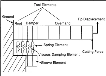
4.2 Dynamic Response Analytic Approach 56
4.2.1 Tool and Sleeve Elements
4.2.1.1 Tool and Sleeve Element Stiffness [IKl] 4.2.1.2 Tool and Sleeve Element Mass: [Mel] 4.2.2 Spring Element Stiffness: [Kext]
4.2.3 Viscous Damping Element Damping Constant: [Cext] 4.2.4 Boundary Condition: Ground
4.3 Model Implementation 66
5 Rapid Prototyping and Testing 68
5.1 Dynamic Response Testing 68
5.2 Rapid Prototypes 72
6.1 Viscoelastic Demonstration Prototype 74
6.2 Viscoelastic Ring Prototype 81
6.3 Discussion 88
7 Fluid Damped Tools 89
7.1 Hydrostatically supported tool 89
7.2 Collet supported squeeze film damped tool 90 7.2.1 Straight Shaft
7.2.2 Augmented Shaft 7.2.3 Waisted Shaft
7.3 Sleeve Supported Squeeze Film 99
7.3.1 Effect of sleeve compliance 7.3.2 Effect of fluid viscosity 7.3.3 Dynamic response parameters
7.4 Discussion 105
8 Enlarged Shaft Diameter Tools 107
8.1 Tapered and Stepped Tool 107
8.2 Discussion 108
9 Metal Cutting Tests 111
9.1 Results 111
9.2 Discussion 115
10 Conclusions 117
10.1 Outcomes 117
10.2 Recommendations for future work 117
Bibliography 119
Appendix A: MATLABTM code for Timoshenko beam finite element model. 120
Appendix B: Frequency and damping measurement repeatability 126
Appendix C: Heat shrink tolerances EXCELTM spreadsheet 127
Chapter 1: Need for a low cost chatter reduction solution
1.1 Chatter in High Speed Machining
In metal cutting, machine spindle speeds are slowly but continuously increasing due to the improved part surface quality and improved metal removal rates that high speed machining provides. The improvement in performance at high speeds is largely due to the reduction in cutting forces as more tooth passes are made to remove a given amount of material (King 1985). The benefits of high speed machining are especially attractive in applications such as mold making and rapid prototyping where complex geometries, smooth surface finishes and fast cycle times are critical to the successful, timely launch of a new product. Due to the widespread applicability and continuous development effort in the area of high speed machining, analysts in the machine tool industry expect that machining speed will show slow but continuous growth into the next century. (Lewis 1996)
To keep pace with customers' desire to machine at faster and faster speeds, machine tools and their complimentary industries will have to develop products that address the special needs in high speed machining. One problem associated with high speed machining is that chatter occurs as the higher frequency modes of vibration associated with the cutting tool are excited.
Chatter is a violent vibration between the cutting tool and the workpiece that results in poor surface quality and damage to the cutting tool or even the machine.
the portion of the cutting energy transmitted to the system. (Stephenson 1997) The most common approach to eliminate chatter is to lower the excitation energy by reducing the metal removal rate when it is encountered under specific cutting conditions. While this approach is preferred to damaging the part, tool or machine, it too can have far reaching negative economic impact. Procedures and products are available for chatter reduction, but they have limited applicability due to their small range of effectiveness or prohibitive cost.
Due to the lack of widely applicable solution for chatter reduction, high speed machining is only slowly gaining acceptance in those applications where quality and speed greatly outweigh cost considerations. For high speed machining to become a practical reality in common practice, where quality, speed and cost are equally important, an effective low-cost solution for chatter reduction will have to be found.
1.2 The Mechanism of Chatter
Chatter, or self excited vibration, is not induced by external periodic forces but from the dynamic cutting process itself. Figure 1.1 below shows that the cutting forces encountered in milling can be approximated by a saw tooth function.
20 15 z 10 5 -5-0.00 0.01 0.02 0.03 0.04 0.05 0.06 Time, s
Figure 1.1 Spindle torque measured in up milling. (Smith 1994)
Chatter occurs when forces from the cutting process excite one or more of the natural modes of vibration of the machine tool system. A typical deflection/force transfer function for a carbide endmill in a spindle showing the resonant peak associated with the first cantilever mode is shown in Figure 1.2.
10.2 I-O 03 o 10 -3 10 100 200 300 400 500 600 700 800 Frequency (Hz)
Figure 1.2: Typical dynamic response of a machine tool system. (Q=14) The force required for this excitation can come from a hard grain in the work piece, the individual cutting edges of the tool entering the work piece, or from deformities in the work piece or cutting tool edge. Such conditions can result in impact forces which feed energy over a broad spectrum of frequencies to the machine tool system. In milling, as the spindle speed increases, the period of the saw tooth cutting force decreases and the
cutting forces decrease since more teeth passes are made to remove a given amount of material. At very high spindle speeds, the power required to remove a given amount of material is actually lower than at slow speeds. This results in a further reduction in cutting force at a given feed rate. The reduction in cutting force results in better surface finishes while the ability to increase the feed rate increases the metal removal rate. Figure 1.3
compares the frequency content of several saw tooth trains of equal power but different spindle speeds. Note that as the spindle speed increases and the saw tooth amplitude decreases, the force amplitude at higher frequencies increases relative to the force amplitude at low frequencies. When the feed rate is increased at high spindle speeds, thereby increasing the amplitude of all frequencies in the input spectrum, the high frequency components of the cutting forces input to the system become significant.
0.5 0.45 - 3000 RPM - 6000 RPM 0.4 --- 1200 RPM - - 24000 RPM 0.35 , 0.3-L0.25 0 15 0.1 0.05 -- 0-0 500 1000 1500 Frequency (Hz)
Figure 1.3: Relative frequency spectrum of saw tooth cutting forces at various spindle speeds and constant material removal rate.
This could explain why the high frequency cantilever mode of the tool (around 500-1500 hz) which is inactive in normal machining, can cause vibrations that result in poor surface finish or even chatter in high speed machining.
To help understand how vibration at the tool tip can lead to chatter, a block diagram for the feedback process responsible for chatter, as described in Tlusty's theory (Stephenson 1997), is shown in Figure 1.4. If the impact force associated with cutting contains enough energy at a natural frequency of the system, the system will vibrate at that frequency. This vibration results in the tool cutting a wavy surface (yi) in the work
piece (primary feedback). Figure 1.5 illustrates the surface waviness generated in various metal cutting operations. Under certain conditions, the next pass of the vibrating tool, or
flute in the case of milling, can align with the wavy surface just cut (yi-/) to cause variations in the chip thickness (regenerative feedback).
The degree of constructive or destructive alignment of the vibrations depends on the phase lag (E) between cutting events at a single point and the overlap factor ()'. In milling, at a given frequency of vibration, f in hertz, s can be calculated from the relation.
e= 2 z- N Eqn 1.1
where n is the spindle speed in revolutions/sec, z is the number of teeth per revolution, and N is the number of whole oscillation cycles between subsequent cuts at a single point (see Figure 1.5). Note that in Figure 1.5 that the largest variation in chip thickness
corresponds to = 1800.
The variation in thickness of the chip formed due to these vibrations causes fluctuations in the cutting force proportional to the width of cut (b) and the cutting stiffness of the material (kd) 2. These fluctuations in cutting force can further propagate
1 In general, t= 1 in milling since the surface being cut by the current tooth or flute is entirely the product of the previous tooth or flute. In thread cutting, 0O since the cut zone never overlaps the most recently cut
surface.
2 Typically, kd is 2.9 X 10S psi (2 X 10⁹
Pa) for cutting steel.
the amplitude of vibration and can eventually lead to instability if the vibration is not sufficiently damped.
Figure 1.4: Block diagram of machining process characteristics that lead to chatter. (Stephenson 1997)
(plunge cut)
Chip thickness variation
Figure 1.5: Surface waviness generated in metal cutting operations. (Tlusty 1985)
Using this model for the cutting process, the criterion for stability requires that the current amplitude of vibration, yi, must be less than or equal to the amplitude of vibration
Structure Dynamics
during the previous pass of the cutter, yi-j. Otherwise, the amplitude of vibration increases in each subsequent pass and the system becomes unstable.
From the transfer function, the ratio of the current amplitude of vibration amplitude of the previous cut is given by:
Yi - G( w)
yi- G(a)+k I
k, .b
to the
Eqn 1.2
To find the limit width of cut for stability, blim, we set the magnitude of this ratio equal to 1, the criterion for stability. We also recognize that at any given frequency, the amplitude of vibration corresponding to e= 180 is just the projection of the magnitude of the transfer function projected onto the negative real axis as shown in Figure 1.6.
Im
Proiection
Re
TF(f)
Figure 1.6: Significance of the negative real part of the tool tip deflection/force transfer function.
The resulting expression for the limit width of cut is given by:
b im = Eqn 1.3
2-kd -Re{G()}(-max)
where Re {G( w))},_max is the maximally negative value of the real part of the deflection/force transfer function at the cutter.
1.3 The Costs of Chatter
1.3.1 Poor part quality
If a chatter problem in a metal cutting operation goes un-remedied, the part quality suffers. During chatter, vibrations can cause the cutting edge to leave the work piece entirely and upon its return, impact and dig deep into the work piece. This results in a high pitched noise for which the phenomenon is named. It also results in a damaged part surface where the depth of cut varies from the nominal and possibly beyond the
acceptable tolerance limits for the part. Even if part damage does not occur, the
amplitude of the chatter vibrations can cause surface waviness beyond the tolerance limits of the part.
1.3.2 Accelerated tool wear
Chatter problems impact the manufacturer's costs in other ways as well. The impact between the tool and the workpiece also damages the tool or at the very least causes premature tool wear. As a result, the manufacturer incurs costs of greater tool consumption and tool changes which reduce output.
1.3.3 Accelerated machine wear
In addition to the workpiece and tool, the machine tool can also suffer damage due to chatter. Machine tools are not generally designed to handle high amplitude vibrations on a continuous basis. Chatter vibrations can damage spindle and linear axis bearing surfaces and lead to accelerated aging and high maintenance and depreciation costs.
1.3.4 Reduced output
Since products that fail to meet the customer's specifications cannot be sold, chatter must be avoided. If no other remedy can be found, metal removal rates must be reduced until vibration free performance is obtained. This reduced output increases the machining time required for the part.
One result of longer machining time is a higher manufacturing cost. In
competitive markets, increasing the selling price of a product to maintain profits is not an option since it usually leads to reduced market share and revenue which could jeopardize future projects and the health of the business. This means the manufacturer has to accept a smaller margin to maintain the target selling price, thereby reducing or even eliminating the profits.
A potentially more devastating effect of reduced output arises if the increased machining time causes a delay in the critical path to a product launch. For example, consider an injection mold required for a plastic part in a new product. In order to avoid chatter, the metal removal rate in machining the mold is reduced by 50%. If the expected machining time was 200 hours, it would now be 400 hours. Assuming the machine could be run 100 hours a week, this results in a 2 week delay of product launch since the mold is on the project's critical path. Since other companies might be launching
competing products at the same time, the delay in product launch could result in lost revenue. In markets with high sales volumes, short product life-cycles and customers who are fast to adopt new products, the difference in profitability due to only a few weeks delay can be staggering. A detailed quantitative analysis of this scenario is given in (Ulrich 1993).
1.4 Currently Available Methods of Chatter Reduction
1.4.1 Universally available methods
Chatter problems are most often the cause of the machine tool or work piece structural dynamics. As a result, the universal methods of chatter reduction discussed below, which do not modify the machine tool structure in any way, are limited in their applicability.
1.4.1.1 Minimizing the tool overhang
In conventional milling, increasing the stiffness of the tool by reducing the overhang length as much as possible reduces the amplitude of vibration. This is due to the fact that the input force spectrum is dominated by low frequency components at conventional speeds. The machine tool system's response to this type of input force is dominated by the static compliance of the system rather than the resonant peak response at one of its natural modal frequencies.
1.4.1.2 Reducing the cutting tool rake angle
The rake angle is the angle of inclination between the leading edge of the cutting tool and the part being cut. As a chip of given thickness is sheared from the work piece, a small angle of inclination generates smaller reaction forces at the tool than a large angle of inclination. For the same reason, variations in cutting force for a given amplitude of vibration are also smaller with a smaller rake angle. As a result, it is common practice to grind tools with as small a rake angle as possible without sacrificing the integrity of the cutting tooth structure.
1.4.1.3 Radiusing the cutting tool
Another approach to chatter avoidance taken by experienced machinists is to grind the sharp point of a sharpened cutting tool into a slightly radiused point. A radiused point does not penetrate the workpiece as readily as a sharp point so for a given variation in cutting force, the deflection of the tool tip, and thereby the amount of energy stored in the cantilevered tool that can lead to chatter, is minimized.
1.4.1.4 Damping materials
On a few lucky occasions, machinists can sufficiently dampen the problematic mode of the machine tool system by using visco-elastic damping materials to mount certain components of machine tool. However, more often than not, the small percentage of extra damping does not effect the problematic mode or is not enough to completely eliminate the chatter problems.
1.4.2 Currently available chatter reduction products
Certain products are available to increase the machine tool system's resistance to chatter in cases where the universal approaches to chatter reduction are not sufficient or cutting parameters to yield stable machining cannot be easily found. However, due to the high purchase and implementation costs associated with these solutions, they are only applicable in cases where the part being produced warrants extensive machining process development or the cutting tool facilitates the use of renewable cutting inserts. Again, in mold making or rapid prototyping, where fast cycle times and small diameter milling tools are required, neither of these luxuries exist.
1.4.2.1 CRAC
A system for chatter recognition and control known as CRAC has been developed at the University of Florida and Manufacturing Laboratories, Inc. This system can
distinguish the audio signal of a stable cutting process from one that is chattering. Once chatter is detected, the system can automatically adjust the cutting feed rate or spindle speed to return the system to stability. When this system is coupled with an adaptive control system, the machine can automatically catalogue the spindle speeds and axial depth of cut that result in the highest metal removal rate. (Tlusty 1997)
While this system does simplify the practitioner's search for the maximum metal removal rate under stable cutting conditions, it does not improve the damping of the system to make it more resistant to chatter. Hence, the machine tool's maximum productivity rates are simply found, not enhanced.
1.4.2.2 Tuned Tooling
Kennemetal Corporation markets tunable steel boring bars that incorporate an internal damper in the tool overhang. The product is pictured in Figure 1.7. These boring bars can operate from 6:1 to 10:1 length-to-diameter ratios. This concept can also be extended to large diameter milling cutters. The tool overhangs must be tuned for a given ratio by using the tuning device to measure the dynamic response and adjusting the internal damper until the dynamic response is minimized.
Figure 1.7 Tuned tooling and tuning device from Kennemetal Corporation. While tuned tooling can help a machine tool achieve better surface finishes and tighter tolerances than it could without the product, it is only applicable in large diameter applications where the cutting edges of the tool can be separated from the tool overhang. To incorporate the internal damper into small diameter, disposable end-mills, and to require that each tool be individually tuned, could be prohibitively expensive.
1.4.2.3 Lanchester Vibration Absorber
The Lanchester Vibration Absorber is another approach used to enhance damping and reduce chatter in boring and large diameter milling. The device consists of a damper mass and damper. A practical example by Hahn is shown in Figure 1.8.
-- dR
In the example shown, the viscous damper by Hahn consists of a mass m2 which is
housed in a viscous medium trapped in the bored-out end of a bar near the tool. The optimal radial clearance dR depends on the viscosity of the damping medium.
Commonly, oil is used as the damping medium. In the practical design of the device, m2
should be made as large as possible and the damper mass and housing bore should be held to a high standard of surface finish. (Tobias 1965)
While the device has given good results in large diameter boring and milling, it would be difficult to satisfy the practical design requirements of mass and surface finish in the small- diameter, disposable end-mills used in mold making and rapid prototyping.
1.4.2.4 Stiffer Tooling Systems
The stiffness of the tool holder - spindle interface and the tool -tool holder interface have been areas of major improvements in recent years. There are a number of competing designs in the tool holder - spindle interface. The traditional taper interface tends to open as the spindle speed increases, thereby reducing the grip force or drawing the tool further into the spindle. The HSK design, shown in Figure 1.9, uses interior clamping which becomes stronger as the speed increases and a separate surface to locate the tool axially. Due to the face contact between spindle and tool flange the stiffness is 5
-7 times higher compared to tapered connections (Diebold Goldring Tooling 199-7). However, in long tool applications, the stiffness of the tool is an order of magnitude
lower than the holder anyway, so the stiffness of the tool holder -spindle interface is not a significant concern.
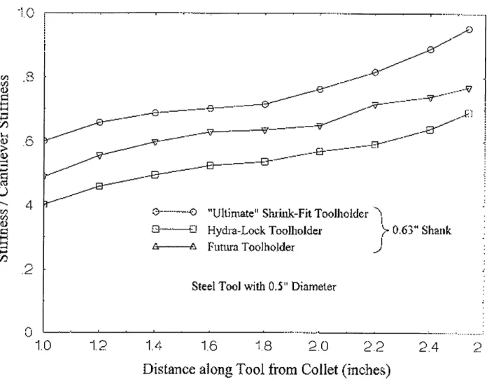
Figure 1.9: An HSK toolholder in the unclamped and clamped position. (WWW 1997) In the tool-tool holder interface, substantial increases in stiffness and shortening of the overhang have been achieved using shrink fit tooling. A comparison of the static stiffness
of three tool holding systems is shown in Figure 1.10.
" : ... ...
----f~----
i~--~c~~c -v ~I---_
,---Ei---- f3-~~---.--.. "Ultimate" Stuik-Fit Toolholder
--- 1 Hydra-Lock Toolholder
A----A Futura Toolholder
Steel Tool with 0.5" Diameter
1.4
1.6
2.0
2.2
Distance along Tool from Collet (inches)
Figure 1.10: Comparison of static stiffness achieved by different tool holding approaches. (Shoffa 1997)
Note that the shrink fit tool holder results in greater static stiffness than the hydraulic or conventional slit collet from Futura Inc.. One possible explanation for the performance
- 0.63" Shank
1.0
1.2
measured is that the level of pre-load pressure generated to hold the tool is largest in the shrink fit design.
The shrink-fit tool holder system from Universal Tooling Division comes with an induction heating unit that allows the customer to heat only the tool holder so the cooler and temporarily smaller tool can be replaced. The normal cycle time for changing tooling is only 7 seconds, making it as convenient to use as the hydraulic or slit collet designs.
A tool holder design from Universal Engineering, shown in Figure 1.11, incorporates both the HSK spindle interface and the ShrinkerTM shrink fit tooling interface into the same tool holder and is quite possibly the most statically stiff tool holding solution available.
Figure 1.11: Toolholder from Universal Engineering incorporating the HSK and ShrinkerTM designs. (WWW 1998)
The design does not, however, incorporate any device to increase the damping of the system. Therefore, at high spindle speeds, the machining process is still susceptible to high frequency chatter at the tool's resonant frequency.
The stiffness of the tooling system can also be increased by using a tapered tool. Tapered tools are much stiffer than standard straight tools of equal length and therefore provide better surface finishes. However, they are more expensive and may require the
use of a 5-axis machine to cut parts with straight vertical walls (Stilwell 1998) (See Appendix D).
1.5 Motivation
Upon analyzing the causes of chatter and the approaches available to eliminate it, it is apparent that no product or procedure currently exists to enable faster metal removal rates or improved surface finishes in a wide variety of applications that require small
Chapter 2 Project Planning for Rapid Technology Development
2.1 Balancing Time with Resource Burn
Given the need for tools with improved damping, an efficient method for developing new technology products is required. The development of new technology products often
differs from the development of new generations of established technologies. The lack of information about a well defined customer group and performance data for the
technology under consideration often requires that development tasks be delayed until the design direction is finalized so that development resources can be used most efficiently. An alternative approach is to conduct many tasks in parallel toward potential and
unidentified opportunities rather than in a serial fashion for maximum development speed once the desired design direction is finalized. The distinction between Resource Efficient Technology Development and Fast Technology Development is discussed below. The following chapters follow the outline set forth in this section and illustrate how the Fast Technology Development method, with its multiple parallel design directions, was used to develop the chatter reduction solutions investigated in this project.
2.1.1 Resource Efficient Technology Development
Resource Efficient Technology Development, represented in Figure 2.1, is
preferred in projects that require large resource commitments due to the complexity of the technology or the large capital cost incurred in developing the product. In this situation, it is risky to begin developing concepts, prototypes and detailed designs for the product before a design direction is established. The risk can be illustrated by considering a
simple break-even analysis. Such an analysis would show that large amounts of money spent early in the project are harder to recover through product sales than large
expenditures later in the project. Instead, it is wiser, in the case of large projects, to wait until the company's understanding of the technology and customer are mature so the duration of the resource intensive phases of the project can be kept to a minimum.
o 7
oo
o o o O
0
1 2 3
Design Direction Certainty
0 0 0 0 O O Project Phase Completion
o 0 o o o0 Rejected Opportunity 0
Potential Opportunity
O * Target Opportunity
4 5 6
Figure 2.1: Time lapse representation of Resource Efficient Technology Development
2.1.2 Fast Technology Development
Fast Technology Development, represented in Figure 2.2, is preferred in projects that can be completed with a relatively small resource commitment. These projects
generally involve a simple technology, small piece of a complex technology, or a well differentiated customer group. Most start up companies are founded by these types of projects. In this case, time to market rather than resource expenditure rate determines the profitability of the project since being late to market can allow a competitor to take an
early lead in market share or installed base. Since it is relatively cheap to develop concepts, prototypes and detailed designs, several different design directions can be explored while knowledge about the technology and customers is built. This knowledge is required to determine the best opportunity to target, but usually takes a long time to build in the case of new technologies and markets.
0O O0
O O O
1 2 3
O Design Direction Certainty
O O O Project Phase Completion
I
O O 0 O Rejected Opportunity O
0 O Potential Opportunity 0
4 Target Opportunity 9
4 5
Figure 2.2: Time lapse representation ofFast Technology Development.
In Fast Technology Development, product developers are encouraged to explore as many design directions as possible, even if there is only a vague understanding of the potential opportunity. Also, phases are sometimes conducted in parallel as long as the resource spending is justified by the certainty that there will be an eventual product. Such an approach has three benefits. First, exploration of a certain design direction might
catalyze the identification of a new opportunity. Secondly, the work done in exploring a particular design direction might be applicable to another design direction for a newly identified potential opportunity. Finally, once the target opportunity is determined, it's likely that many of the phases of development toward that opportunity have already been partially completed thereby reducing the remaining time until product realization.
2.2 Development Process for Chatter Reduction Technology and
Product
The Fast Technology Development approach was used in this project. A three phase development process was used for each design direction. In this section, short descriptions of tasks in the Concept Generation and Evaluation, Concept Development, and Product Solidification and Release phases are given.
2.2.1 Concept Generation and Evaluation
2.2.1.1 Benefit Proposition
The benefit proposition is a statement of the product's purpose with respect to the company and its customers that is used to guide the product definition.
2.2.1.2 Functional Requirement Identification
The functional requirements that the product must fulfill are based on testimony from experts and potential customers and an analytic understanding of the activities and parameters important to machining performance.
2.2.1.3 Enabling and Complementary Technologies Identification
Once the factors controlling the functionality of the product are determined, technologies that can deliver the required functionality are identified. Technologies which are currently gaining popularity with the target customer group are also identified to ensure that the product under consideration will take advantage of, rather than
contradict, strong trends in the marketplace.
2.2.1.4 Conceptual Design
In conceptual design, the enabling and complementary technologies are arranged into a product architecture. The architectural rules such as the functions of modules within the product and the interactions of modules with each other and the environment are defined. The goal of conceptual design is to arrange the architectural elements in a way that will provide the greatest functionality for the cost incurred. However, designs in this phase do not have to be qualified by detailed cost or performance analysis and
relative estimates of performance and costs for the various concepts are sufficient.
2.2.1.5 Concept Pre-Selection
In this phase concepts are selected based on their ability to meet the functional requirements. Only those designs that can be eliminated on the basis of their conceptual design without more detailed analysis are discarded.
2.2.2 Concept Development
2.2.2.1 Critical Parameter Identification
Critical Parameters are the product design attributes that effect the product's ability to meet the functional requirements. These critical parameters are determined by developing an analytic understanding of the fundamental physical principles that govern the product's performance.
2.2.2.2 Performance Modeling
Some Critical Parameters cannot be modeled analytically so they must be numerically simulated on a digital computer. The performance model helps the product development practitioner codify their understanding of the parameters that control the product's performance. The model must be refined as the understanding of the product's performance grows. A well developed performance model can help predict the effect of design changes and tolerance uncertainties.
2.2.2.3 Parametric Solid Modeling
A Parametric Solid Model helps in quickly developing a conceptual design into a realistic detailed design. Because the solid model forces the product development
practitioner to consider the realistic constraints in manufacturing and assembling the product, it can help identify critical parameters that were overlooked before. The solid model can also be easily modified to yield production drawings later in the project when the design parameters are finalized.
2.2.2.4 Rapid Prototyping
Before the detailed production design is completed, parts of the product can be made to test the validity of the conceptual design and the accuracy of the performance model in predicting the product's performance. The results of testing on rapid prototypes can indicate that the model needs to include another level of detail to be sufficiently accurate. Testing done with rapid prototypes can also help gauge the performance that can be expected from the product and the customer's acceptance of the product.
2.2.2.5 Critical Parameter Verification
After experiments are conducted with the rapid prototypes, the product development practitioner must verify that the product attributes contributing the
functional performance of the product are sufficiently understood. If a product is released without understanding the critical parameters that control the product's performance, solutions may not be readily available when problems are reported in the field. It is not necessary to understand every critical parameter before releasing the product, but the risk associated with the lack of understanding should be assessed before making the decision to release the product.
2.2.3 Product Solidification and Release
2.2.3.1 Model Optimization
Using a reasonably accurate model, the performance of the product can be optimized without building several iterations of the hardware, thereby saving time and money. A numerically simulated model can be optimized by adjusting the values of the
critical parameters and seeking the optimal combination of performance characteristics. An analytic model can be solved to directly output the required critical parameter value for a desired level of performance.
2.2.3.2 Manufacture to Detail Design
Once the performance model is optimized, the resulting critical parameters values can be applied to the solid model. From this model, drawings are quickly generated and parts can be made. For parts that require production tooling with a long lead time, preparations for manufacture are made in parallel to the detail design. To speed the development, long-lead-time tooling is produced in stages as more and more details become available. As a result, only slight modifications to the tool are required and parts can be made available quickly after the design is finalized. In such cases, major design changes that are not required for the functionality of the product are deferred until the next development cycle of the product so as not to delay its initial release.
2.2.3.3 Product Validation Testing
In validation testing, the product is tested under field conditions. This may include tests conducted by the product's developer or by customers chosen by the developer to act as test sites. This phase also includes quality assurance testing in which the developer must verify that the processes used in manufacturing the product can consistently deliver the product attributes required.
2.2.3.4 Risk Analysis Based Product Release
No development project is ever completely finished. In every project, there are unknown critical parameters and possible design improvements that could effect the performance of the product in the market place and in the field. The product developer must balance the risk of releasing the "unfinished" product against the cost of delaying the introduction and subsequent revenue of the product.
Chapter 3 Concept Generation and Evaluation
Concept Generation and Evaluation is the first phase of a new product development program. The activities in this phase are geared toward generating and identifying product concepts that are most likely to yield successful products. The steps are:
1. Statement of Benefit Proposition
2. Identification of Customer Needs and Functional Requirements 3. Identification of Enabling & Complementary Technologies 4. Conceptual Design
5. Concept Evaluation
3.1 Benefit Proposition
A benefit proposition statement usually guides the concept Generation and Evaluation phase of a project. This short statement describes how the product offering delivered by the current project will attract customers away from competitive offerings or create new customers. It is important that the benefit proposition be based on a clear and accurate understanding of the various customer desires that effect the product's success as well as the short and long term goals of the corporation. Some possible purposes for a new product program might be to satisfy an un-addressed customer need, fill out a company's product portfolio, increase the volume and therefore reduce the per part cost of an expensive production process, or help the company or customer transition to the next generation of technology in an industry. For this reason, in an established
corporation, a team representing the Engineering, Finance, and Marketing functions best handles the task of generating a balanced and realistic benefit proposition. Also, in an
established organization, the benefit proposition statement is generated during an activity called Portfolio or Market Attack Planning that occurs on a regular basis to specify the company's plans for each of the market spaces it operates in. In the case of a startup company or a new venture idea in an established company, the benefit proposition is not necessarily constrained by an established structure and can be considered part of the concept generation phase as is the case in this project.
A good way to elicit the benefit proposition statement is to ask, What will the product do for the company or the customer and how will it do it? The following benefit proposition statement was used as a guide for this project.
A low cost product that offers a chatter reduction solution for
operations requiring long tool overhangs (greater than 5:1) that can
be used in all existing machine tools without expensive modifications
to the machine or to customer processes.
3.2 Customer Needs and Functional Requirements
The target customer groups for this product are job shop managers and machine operators who mill aluminum molds and deep pocketed prototype parts. This group would have the most incentive to purchase a product that could improve the achievable material removal rate. Most job shops working with aluminum are still milling at conventional speeds, but sales of higher speed machines are increasing and awareness of the benefits of high-speed machining is growing. For this reason, the product should
benefit the large installed base of conventional speed operations, but also be able to ride the growth in high speed machining by providing benefits in that regime as well.
3.2.1 Performance
3.2.1.1 Dynamic Stiffness
The dynamic stiffness of the tool is the inverse of the deflection/force transfer function measured at the tool tip and is therefore frequency dependent. In relation to chatter, the most important value is the dynamic stiffness at the resonant peak frequency. Dynamic stiffness is measured in lbs/inch and can also be represented as a ratio,
Q,
to the static stiffness of the tool.Q= Eqn 3.1
KD
Q
is known as the quality factor or the amplification factor. Since it normalizes the dynamic stiffness relative to the static stiffness,Q,
is a good indication of the damping in the system.Q
is related the damping factor by : (Slocum)Q = 2 Eqn 3.2
For very small damping factors <.2 found in machine tool systems,
Q
can be approximated as1
Q-
Eqn 3.3In machining aluminum, the most common limiting factor to material removal rate is the onset of chatter at the machine tool system's natural frequency so by increasing
the damping, which is analogous to reducing
Q,
the chatter-free material removal rate limit will be increased.3.2.1.2 Static stiffness
The static stiffness of the tool determines the deflection due to sustained or low frequency input forces, the smaller the deflection, the higher the accuracy of part being produced. Since a high static stiffness yields better part accuracy and surface finish, the tool holder should maintain the static stiffness available through currently available tool holders.
3.2.2 Functionality
Long slender end mills are used in cutting deep pockets in prototype parts or injection molds or when cutting complex parts on NC machines. In these applications, shorter tools that are less prone to chatter cannot be used because the machine tool spindle would interfere with the work piece. The tool holder developed in this project should maintain that functionality by keeping features external to the tool holder should be small enough that they will not cause problems in the tight cutting geometries
encountered by the end user.
3.2.3 Costs
While certain members of the customer group are able to select products based on performance only, the majority of customers in this group place a high weighting factor on cost in their decisions to purchase tooling and tool holder systems. A product that introduces even slight cost increases will be received with skepticism and must therefore
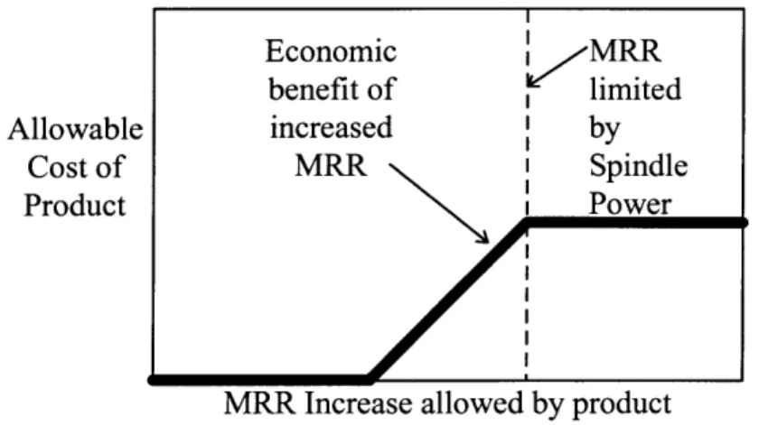
provide a dramatic performance increase. In particular, the economic benefit of the higher material removal rate allowed by the product must more than offset the product's cost. If significant costs are introduced, however, it could jeopardize the initial salability of the product regardless of the performance increase. After chatter is removed as a bottleneck to the material removal rate (MRR), the limiting factor becomes the available spindle power. Since most spindles in use today are designed for conventional speeds and feeds there is a limit to the material removal rate they could achieve without expensive modifications even if chatter were completely eliminated. The factors affecting the allowable cost are illustrated in Figure 3.1.
Economic i> MRR benefit of limited
Allowable increased by
Cost of MRR I Spindle
Product i Power
MRR Increase allowed by product
Figure 3.1: Allowable product cost vs. Material Removal Rate (MRR) performance enhancement
3.2.3.1 Tool costs
Since tools are expendable, it is possible to spend more on tooling than on the machine tool during the life of the machine. As a result, a tooling cost increase of only a few percent can, over time, mean a significant increase in overall costs. Due to their high
sales volume, tools of standard form are relatively inexpensive when compared to custom-made tools. For this reason, tool holder that requires modifications to the tool should be avoided.
3.2.3.2 Machine tool modifications
While small modifications to the machine tool might be allowable, the tool holder should not require modifications involving a significant investment of money or time
3.2.3.3 Tool replacement time
In environments with significant machine uptime, the time required to replace a worn tool with a new one can become an important part of the overall lead-time for a part if the replacement time is long. In the tool holder under development in this project, the time required to replace the tool should be kept to a minimum.
3.3 Enabling Technologies
To catalyze product concepts that would be able to increase the damping of the machine tool system, three technologies that well known for their damping properties were explored. Those technologies are introduced in this section.
3.3.1 Hydrostatic Bearings
Hydrostatic bearings are a class of non-contact bearings that use a thin film of externally pressurized oil or water based coolant to support a load. A journal type hydrostatic bearing could find application in the cylindrical geometry of the interface between the tool and the tool holder. A self-compensated rotary hydrostatic bearing could resist deflections to the tool shank by diverting the external pressure from the
surface retreating from the tool holder to the opposed region advancing to the tool holder, thereby exerting a force on the tool shank that is opposed to the deflection. Kevin
Wasson 3and Alex Slocum of the Precision Engineering Research Group at MIT
developed the self-compensated rotary hydrostatic bearing4 that serves as the basis for the concept pictured in Figure 3.3 (Wasson 1996).
The damping capacity of a hydrostatic bearing comes from the energy dissipating viscous flow developed when the bearing is deflected. The liquid in the bearing gap is forced over restrictive lands that separate the pressurized region from atmospheric pressure. Since the clearance of the restrictive lands is on the order of 0.001", and the opposing pressure generated for a given amount of flow is inversely proportional to the cube of the gap, hydrostatic bearings can have huge damping constants. However, a small gap also generates higher self-compensation pressures to resist the deflection because the percent change in the flow exit area is increased. This can limit the deflection available to generate the fluid flow that results in damping. As a result, an optimal design will balance the stiffness of the hydrostatic bearing with the damping factor of the bearing.
3 Dr. Wasson is now Chief Engineer at Aesop, Inc. (Bedford, NH). [email protected]
3.3.2 Constrained Layer Dampers
Constrained layer dampers are completely passive and operate by subjecting a viscous material to the relative motion between a stable structure and a vibrating structure. As a result, the energy in the vibrating structure is dissipated by the forces developed in deflecting the viscous material.
3.3.2.1 Viscous
Completely viscous constrained layer dampers are found in lubricated journal bearings. The damping mechanism is similar to that in hydrostatic journal bearings, but since there is no bearing pocket, the restrictive land acts on the entire area of the fluid layer. This means that the damping factors achievable in plain journal bearings are larger than those achieved in hydrostatic bearings with the same gap. Closed end journal bearings restrict the fluid flow in the axial direction and thereby generate larger flow forcing pressures. As a result, closed end journal bearings develop larger opposing forces than open end journal bearings with the same gap size.
3.3.2.2 Viscoelastic
Viscoelastic damping materials can also be used in constrained layer dampers. Here, the damping factor depends on the loss factor of the material. A higher loss factor results in more damping. Because the material is also elastic, the design can be balanced for the proper combination of stiffness and damping. The damper can be made stiffer by using a thinner layer of material.
3.4 Complimentary Technologies
Complimentary technologies are strong or emerging technologies that are related to the product. The product will be more successful if it utilizes or is at least compatible with these technologies because of the their favored or quickly emerging status in the market place.
3.4.1 ShrinkerTM tool holding system
The ShrinkerTM shrink fit tool holding system is quickly gaining market share due to the stiffness improvements it provides. The tool holder design should incorporate a shrink fit interface since it is the stiffest tool holding approach currently available. We should also note that the increased stiffness comes at a cost. Since the Shrinker tool holder is all one piece, the tool holding geometry is not interchangeable. Instead of switching the collet for a different diameter tool, a different tool holder must be purchased. This could require a significant investment in a shop where several tool holders in a variety of diameters are required.
3.4.2 HSK coupling
The HSK tool holder interface offers a definite improvement in stiffness over the traditional CV taper at high spindle speeds. Its use is currently limited, but if the trend toward higher spindle speeds continues, as it is expected to do, the HSK coupling may become the dominant coupling system. The tool holder product should be compatible with this coupling system as well as the traditional CV taper system.
3.5
Design Concepts
3.5.1 Concept Tree
The concept tree in Figure 3.2 shows the different chatter reduction solutions that were considered during the course of this project. Short descriptions of each conceptual design are given in the following section.
3.5.2 Concept Descriptions
3.5.2.1 Hydrostatic damper
The hydrostatic damper5 concept shown in Figure 3.3 consists of a standard tool heat shrunk into a bearing housing which itself is heat shrunk into a solid collet. A possible benefit of the hydrostatic bearing design is that the fluid in the bearing pad, or pocket, provides static stiffness and damping to the tool shank.
Collet aring
Bearing housin Standard
through-cooled
tool
Pressurized coolant
Through-tool
Inlet gap Leakage flow coolant flow
Figure 3.3: Hydrostatically damped tool holder.
The static stiffness is realized when pressurized coolant flows through the feed hole through the inlet gap and to the bearing pads located around the circumference of the bearing. Each bearing pad is connected to the inlet gap on the opposite side of the
circular bearing housing with a flow channel and is separated from other bearing pads by a restricting land. When the tool shank is deflected upward, the bottom inlet gap opens while the upper inlet gap closes. This changes the relative restriction to the fluid flow through each bearing pad and provides a pressure differential on the tool shank that results in a net downward force to oppose the deflection. The static stiffness of the bearing pad can be estimated by: (Slocum)
5 Aesop, Inc patent pending.
KHS- P TOT Eqn 3.4
Where Ps is the source pressure and AToris the total bearing pad area and h is the nominal inlet gap or radial clearance of the hydrostatic bearing.
The damping factor of a rotary hydrostatic bearing depends on the land to pocket ratio of the bearing. Only the fluid flow across the axial and radial land regions is responsible for the dissipative damping effect since flow across the pocket region is relatively unrestricted. For a completely smooth (no pockets) hydrostatic bearing with open ends, the damping constant is:
C - h Eqn 3.5
Where R is the radius of the bearing, L is the length of the bearing and t is the dynamic viscosity of the fluid.
The pressurized fluid required for the hydrostatic bearing could be supplied by the pressurized through-tool coolant systems found on many modem machine tools. The design requires a negligible amount of additional pumping power because the leakage flow through the bearing clearance is insignificant compared to the coolant flow through the tool.
In trying to package a hydrostatic bearing into a collet, the area of the bearing is constrained so the source pressure required to give any appreciable stiffness benefit will be very high. While through-tool coolant systems with supply pressures up to 5000 psi are available, they are still exceedingly rare. The coolant filter would also have to be made more efficient since particles that might normally be allowed in normal high pressure coolant systems could mar the smooth surface finishes required for the
hydrostatic bearing to function properly. In addition, the design must be balanced since too much static stiffness will not allow enough deflection to generate appreciable damping flow. The fact that this design requires a custom-made solid collet could be another obstacle to its market acceptance if a complementary manufacturer cannot make solid collets readily available.
3.5.2.2 Viscoelastic damper
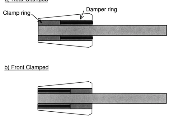
The viscoelastic damper designs shown in Figure 3.4 consist of a steel clamp ring and a damper ring6. The clamp ring is shrunk fit onto the tool or is split so it tightens onto the tool shank as the collet is tightened. The damper ring consists of a layer of elastic material between two steel rings. The outer steel ring prevents the visco-elastic material from being extruded between the fingers of the spring collet. The inner steel ring reduces the friction between the damper ring and the tool shank and thereby eases assembly. The damping material is compliant, so the damper ring conforms to the space between the tool shank and the collet to evenly distribute the grip force of the collet.
a) Rear Clamped
Clamp ring Damper ring
b) Front Clamped
Figure 3.4 a & b: Toolholder designs damped with viscoelastic material can be clamped in the rear (a) or the front(b).
The performance of the damping material in this design is indicated by its loss factor and elastic modulus. The stiffness of a layer of damping material is hysteretic. This means that the strain of the material lags the stress placed on the material and the stiffness of a constrained layer is expressed as a complex value:
E A
KL= - (1+ 7L .i) Eqn 3.6
t
where EVE is the elastic modulus of the viscoelastic material, AL is the area of the constrained layer, t is the thickness of the material and rI is the loss factor.
All materials exhibit hysteretic damping which is also known as material damping. The material damping in metals commonly used for tooling is orders of magnitude lower than the material damping found in specialty damping materials. For this reason, there is opportunity to improve the damping of the machine tool system by introducing a damping material in collet's tool shank support mechanism.
The benefit of this design is that it is compatible with the majority of machine tool and tool holder systems installed today. It requires little to no extra equipment and tool replacement is kept simple.
In this design, a damping material with a high loss factor and high modulus is desired to give good damping and static stiffness respectively. Such a material may be difficult to find since most materials with high loss factor have a low modulus.
It is unclear which of the concept's variations, shown in Figure 3.4 a & b, will perform best. The rear clamped design allows more tool tip deflection for a given amount
of damping than the front clamped design but the front clamped design might not allow enough deflection of the constrained layer to yield sufficient damping.
3.5.2.3 Tapered End-mill
In deep pocketed molds and slotted parts, there is usually a draft angle allowance that allows the tool to be slightly tapered. The recommended allowance for deep pocket molds is about 5 degrees. The tapered tool pictured in Figure 3.5 takes advantage of the draft angle allowance by increasing the diameter at the root of the tool while keeping the cutting diameter small to enable detailed work-piece geometries.
Figure 3.5: Tapered tool for maximum static stiffness.
The benefit of a tapered end mill is the increase in static stiffness over a conventional straight shank tool. A straight tool with a circular cross section has tip stiffness:
3 zEd4
Kstraigt - 64L3 Eqn 3.7
where d is the diameter of the tool and L is the overhung length of the tool. In
comparison, a tapered tool with equivalent tip diameter but larger base diameter, D, has tip stiffness:
3
,ED3dKtapered - 64L3 Eqn 3.8
For a 5 inch long tool with V2 inch tip diameter and a taper of only 5 degrees, the tapered tool is about 20 times more statically stiff than the straight tool which has a constant diameter equal to just the tip diameter. This increased stiffness should reduce the amplitude of vibration for a given amount of cutting force and result in a smoother surface at conventional speeds.
The major drawback of this concept is that the high cost tool is not re-usable. The cost of the solution cannot be amortized over many cycles of tool wear. Also, the
solution does not introduce any damping to the system, so the dynamic stiffness of the tapered tool may not be significantly higher than a standard tool.
3.5.2.4 Squeeze film damper
The viscous squeeze film designs shown in Figures 3.7-10 consist of a tool shrunk fit in a stepped bore tool housing such as a solid collet or sleeve. The rear portion of the housing interferes with the tool to allow the shrink fit while the forward portion of the housing has a clearance fit relative to the tool. The gap in the forward portion of the housing is filled with a viscous fluid through the fill ports. The fluid is trapped with self sealing screws in the fill ports and with a seal on the collet face.
In this design, the damping is a result of the viscous flow generated when the tool deflects and displaces the fluid from it's leading surface. Since the ends of the damper are closed, the fluid is constrained to flow around the thin annular clearance between the tool and the collet. In order to drive this flow, a driving pressure (PD) is generated at the leading surface of the tool to oppose the motion of the tool as shown in Figure 3.6.
Figure 3.6: Illustration of viscous flow and retarding pressure generated by tool deflection in the squeeze film.
This driving pressure acts against the advancing area of the tool and results in a force opposing the tool's motion that is proportional to the tool's velocity. For a completely smooth, cylindrical squeeze film with closed ends, the damping constant is linear with respect to the length of the squeeze film and is equal to:
6fIR3L p
CSF hi Eqn 3.5
4 variations of the squeeze-film-damped tool holder are discussed below.
Collet style
The collet style squeeze-film-damped tool holder employs a solid collet to replace the split collet usually found in collet style tool holders. The solid collet is required to provide a smooth continuous surface for the fluid to flow along. Three variations of the collet style squeeze film damped tool were investigated.
The simplest variant of the squeeze film design employs a standard, straight-shank tool and is shown in Figure 3.7. The static stiffness of this design is much lower than a
comparably overhung standard tool because the tool is unsupported for the length of the clearance and stiffness is inversely proportional to the cube of the length. This design does not allow the user to control the amount of damping or the static stiffness since the diameter of the tool root, which undergoes the maximum strain and is the site of the damping layer, must be equal to the tool diameter required for the desired cut.
Figure 3.7: Squeeze-film-damped tool with straight tool shank.
The augmented shank design, shown in Figure 3.8, allows the tool to have greater static stiffness than in the straight shank design. The root diameter of the tool root is de-coupled from the cutting diameter of the tool so its static stiffness and damping
performance can be tuned to a certain degree. However, the large root diameter could reduce the deflection at the damping layer and result in diminished damping performance since the damping diameter and root diameter are still coupled.