HAL Id: hal-02269998
https://hal.archives-ouvertes.fr/hal-02269998
Submitted on 23 Aug 2019
HAL is a multi-disciplinary open access archive for the deposit and dissemination of sci-entific research documents, whether they are pub-lished or not. The documents may come from teaching and research institutions in France or abroad, or from public or private research centers.
L’archive ouverte pluridisciplinaire HAL, est destinée au dépôt et à la diffusion de documents scientifiques de niveau recherche, publiés ou non, émanant des établissements d’enseignement et de recherche français ou étrangers, des laboratoires publics ou privés.
Conceptual design of a cryogen-free µMRI device
G. Authelet, M. Poirier-Quinot, J C Ginefri, A Bonelli, B. Baudouy
To cite this version:
G. Authelet, M. Poirier-Quinot, J C Ginefri, A Bonelli, B. Baudouy. Conceptual design of a cryogen-free µMRI device. IOP Conference Series: Materials Science and Engineering, IOP Publishing, 2017, 278, pp.012122. �10.1088/1757-899X/278/1/012122�. �hal-02269998�
To cite this article: G Authelet et al 2017 IOP Conf. Ser.: Mater. Sci. Eng. 278 012122
View the article online for updates and enhancements.
Gas gap heat switch for a cryogen-free magnet system
J Barreto, P Borges de Sousa, D Martins et al.
-Cryogen-Free 23 T Superconducting Magnet with a 7.5 T YBa2Cu3O7 Insert Coil
Kazuo Watanabe, Satoshi Awaji, Gen Nishijima et al.
1
Content from this work may be used under the terms of theCreative Commons Attribution 3.0 licence. Any further distribution of this work must maintain attribution to the author(s) and the title of the work, journal citation and DOI.
Published under licence by IOP Publishing Ltd
1234567890
CEC 2017 IOP Publishing
IOP Conf. Series: Materials Science and Engineering 278 (2017) 012122 doi:10.1088/1757-899X/278/1/012122
Conceptual design of a cryogen-free μMRI device
G Authelet1, M Poirier-Quinot2, J-C Ginefri2, A Bonelli1, B Baudouy1
1Irfu, CEA, Unversit´e Paris-Saclay, F-91191 Gif-sur-Yvette, France 2
IR4M, UMR8081, Universit´e Paris-Sud/CNRS, Universit´e Paris-Saclay, Orsay, France E-mail: bertrand.baudouy@cea.fr
Abstract. To perform Micro Magnetic Resonance Imaging (μMRI) analysis on small regions such as skins, articulations or small animals, the required spatial resolution implies to dramatically improve the sensitivity of the detection. One way to go is to use small radio-frequency superconducting coil that allow, among others, increasing significantly the signal-to-noise ratio. The RF probe, constituted of an optimized YBaCuO film coil cooled below nitrogen temperature, must be located no further than few millimeters from the biological region to be imaged in a clinical MRI magnet. To fulfill the medical environment and constraints, a cryogen-free cooling scheme has been developed to maintain the superconducting coil at the working temperature. The cryogenic design is based on a pulse tube cryocooler and solid thermal links inserted in a non-magnetic cryostat to avoid creating any electromagnetic perturbations to the MRI magnet and the measurements. We report here the conceptual design of the cryogenic system with the required thermal performances, the corresponding layout and architecture of the system as well as the main technical challenges met for the construction.
1. Introduction
Magnetic Resonance Imaging (MRI) is a noninvasive imaging technique, used on a daily basis in medical practice to obtain functional and quantitative information. The sensitivity of detection in clinical routine allows obtaining images with a typical spatial resolution of the order of 1 mm3, which does not allow for the analysis of finer structures or magnetic resonance contrast in regions such as the skin, articulations or for small animals imaging. To improve the MRI spatial resolution, one way to go is to increase the sensitivity of the Radio-Frequency (RF) probe used to detect the Nuclear Magnetic Resonance (NMR) signal. This can be achieved by diminishing the size of the probe and its electrical resistivity. In this perspective, miniaturized RF coil prototype has been conceived, based on a transmission line resonator [1], employing the high temperature superconductor YBa2Cu3O7. The reduction in size yields to a better magnetic coupling between the coil and the biological tissue under investigation, with an increase of the received signal intensity and a decrease of tissue-induced noise in the probe. The use of superconducting materials allows also a considerable reduction of the noise of the probe itself. This approach has yielded to the most highly resolved images ever obtained in human and in mouse, with a spatial resolution of (60 μm)3 on a 1.5 T whole-body MRI scanner [2]. The AC losses of superconducting materials as a function of the emitted RF power is, nowadays, one of the principal technological obstacle limiting the use of these materials on a wider scale. To apply this technique to μMRI, RF probe (1 to 400 MHz used for NMR) with higher sensitivity must be developed. This is the main objective of the project SupraSense: the development
2
The highly sensitive detection device will be light, portable, and user-friendly so that it can be put to use in the different imaging systems available in bio-medical research centers. The set up will be designed to optimize sensitivity, one of the critical aspects in μMRI. It will be made up of superficial RF coil, fabricated with HTcS materials, and cooled by the cryogenic cold finger of the cryostat. Its use will be compatible with existing MRI devices. One of the major issues to be addressed is that of the rapid transition (on a time scale less than a ms) of the device from the superconducting state to the normal state, required for imaging.
These fundamental developments will be tested in a 1.5 T whole-body MRI scanner under real imaging conditions. For that matter a medical environment compatible cryostat has been designed and is under construction. This paper reports the conceptual design that has been chosen for such a cryostat in detailing the cryogenic cooling scheme, the different technical solutions retained and the associated thermal budget and mechanical computations.
2. Cryogenic scheme principle and general layout of the μMRI cryostat
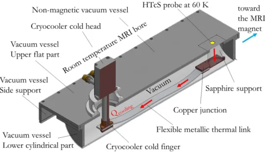
The principal requirements of this cryostat is to maintain the HTcS probe as close to the biological tissue under test as possible at a dedicated cryogenic temperature, around 60 K, under a strong magnetic field in a medical environment. Most of the cryostat will have to be inserted in the warm bore of the MRI scanner magnet. For these reasons, a ”cryogenist-free” environment, i.e, a cryogen-free system working autonomously without the need of a cryogenic expert was chosen. An autonomous cryogen closed circulation loop system with a cryocooler as the cold source was initially considered as described in [4, 5]. But this solution was abandoned due to the numerous metallic parts and the associated weight that contains this solution (condenser, piping). The chosen cryogenic design has been to on-board the cold source on the cryostat as it is presented in the figure 1 and thermally connect the cryocooler to the HTcS coil via solid thermal links. The cold source will be provided by a commercial single stage pulse tube cryocooler with a remote motor. The part of the cryocooler that will be located on the cryostat has no internal moving parts; only the gas motion can produce a very low rate of vibrations. This solution allows minimizing the mechanical perturbations on the HTcS probe and also reducing the effect of the large magnetic field of the MRI scanner on the motor of the cryocooler valve. The cold finger is thermally connected to the HTcS probe by different solid links connected in series. The combination of these thermal links has been chosen to fulfill different requirements. The main thermal link, connected to the cold finger, is a flexible metallic material. The choice of highly conductive aluminum strips has been made to reduce the overall mass of the cryostat. The thermal link, that is supporting the HTcS probe, has been chosen to be in sapphire to fulfill two requirements. This piece must be an excellent thermal conductor and also electromagnetically neutral to minimize the perturbations on the HTcS probe behavior. As depicted on the general layout drawing on the figure 1, copper junction pieces are used to connect the flexible aluminum link to the sapphire support that is attached to the upper part of the cryostat. The length of the cryostat has been chosen long enough (1 m) to provide a sufficient space for measurements on large biological bodies such as small animals or human arms. To maintain a high sensitivity, the HTcS probe, installed on top of the sapphire support, is located a few mm away from the room temperature surface where the biological tissues will be placed. Between the room temperature surface and the probe, a specific insulating piece has been designed to minimize the heat load. This piece as well as the vacuum vessel must be also electromagnetically neutral to minimize the perturbations on the measurements and on the magnetic field of the IRM scanner magnet.
3
1234567890
CEC 2017 IOP Publishing
IOP Conf. Series: Materials Science and Engineering 278 (2017) 012122 doi:10.1088/1757-899X/278/1/012122
Figure 1. General layout and cryogenic scheme of the μMRI cryostat
3. Mechanical design
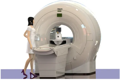
Common solution to build a cryostat for MRI applications is to use a low magnetic material such as high quality stainless steel. In our case, to reduce as much as possible the electromagnetic perturbations, the cryostat will be fully made in polymer materials. The HTcS coil is placed on the isocenter position at the front side of the cryostat. An access is made by a removal flange. Connections and cryocooler are at the back of the cryostat outside of the MRI bore because some of the components are metallic and can induce perturbations. This version of the μMRI cryostat has been designed to fit a peculiar MRI scanner, the Philips Achieva 1.5T [6]. The tunnel bore is 600 mm in diameter and the flare is 1.1 m long. The magnetic isocenter distance from the entrance on the horizontal axis (z-axis) is 750 mm and 150 mm over the bed surface (x-axis). Most of the cryostat will be introduced in the MRI hole as the figure 2 shows and therefore the material of the vacuum vessel was chosen to be in polymer. The vacuum vessel is constituted of two parts. The upper one is a flat flange receiving the cryocooler and the measurements area. The material of this part was chosen to be in PolyEtherEtherKetone (PEEK) [7] to lighten the overall cryostat (ρ=1200 kg/m3). Since, currently, there is no guarantee to have leak-tight welding for PEEK pieces, the lower part will be made in Polytetrafluoroethylene (PTFE) which is more dense (ρ=2200 kg/m3). The vacuum vessel, made also in PEEK, will be supported in the MRI scanner by side supports that will allow the cryostat to slide in and out of the scanner. 3.1. Vacuum vessel upper flat part
The upper flat part must be mechanically designed to support the cryocooler and the HTcS probe. This flange will have necessarily two openings and must sustain also vacuum (around 10−6 mbar) inside. PEEK has been chosen because it shows acceptable mechanical properties with a Young’s modulus of 4400 MPa, a rather low out-gasing and permeation value. PEEK is one of the most technically advanced plastic on the market and is authorized to be used in medical environment and easy to machine. The only inconveniences for our application is that it is rather expensive and does not have good weldability properties due to its specific composition. The figure 3 show the mechanical computation results for the deformation in mm of the flat part of the cryostat. The computations were performed with Comsol R v.3.5 and the following boundary conditions were implemented in the model. The side of the flat flange are clamped
4
Figure 2. Implementation of the μMRI cryostat in the MRI scanner
since it will be bolted in the support vertical flanges. The atmospheric pressure is imposed on the top part whereas 10−6 mbar is imposed on the bottom part. No thermal contraction has been implemented since the flange should stay very close to the ambient temperature. The thickness has been optimized to keep the weight of this part under 10 kg and to have mechanical constraint lower than the yield strength. An average thickness value around 25 mm was found. This design keep the deformation of the flange to a value lower than 3 10−4 mm. The maximum mechanical constraint on the flange has been calculated to be lower than 22 MPa which is 5 times lower than the yield strength (σy=115 MPa) of PEEK.
Figure 3. Mechanical displacement computation of the upper flat part of vacuum vessel. The maximum deformation, 2.83 10−4 mm, is obtained with mechanically clamped sides and a pressure difference of 1 bar.
5
1234567890
CEC 2017 IOP Publishing
IOP Conf. Series: Materials Science and Engineering 278 (2017) 012122 doi:10.1088/1757-899X/278/1/012122
3.2. Cryostat cylindrical lower part
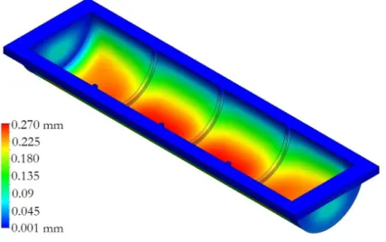
One of the main constraints to design the cylindrical lower part is that it must offer enough space to receive the thermal components and the HTcS coil support. The maximum height allowed is the distance from the bed to the isocenter, minus the upper part thickness. The wall of this lower part is submitted to a 1 bar pressure difference, i.e. vacuum inside and atmospheric pressure outside. To answer to these constraints, the design is based on half cylinder to fit within the bed curve of the MRI scanner. The cylindrical part has to be made from different parts welded together with good mechanical properties, low out-gassing and a low leak rate. Unfortunately PEEK cannot be used to achieve this part because leak-tight welding is not yet guaranteed with such a material. A more common but also expensive polymer, the Polychlorotrifluoroethylene (PTFE), can be used since it has a good machining properties and proven weldability. It is widely used in vacuum technology for years. The mechanical design of this part has been carried out in the same way as for the flat upper flange. Mechanical constraints around 5 Mpa have been obtained for an average thickness of 12 mm. These constraints are much lower than the yield strength of PTFE (σy=35 MPa)). The maximal deformation of the flange is lower than 0.27 mm thanks to three reinforcement ribs that had been added as it can be seen on the figure 4.
Figure 4. Mechanical displacement computation of the PTFE lower cylindrical flat part of vacuum vessel. The maximum displacement value is 0.27 mm.
4. Thermal design
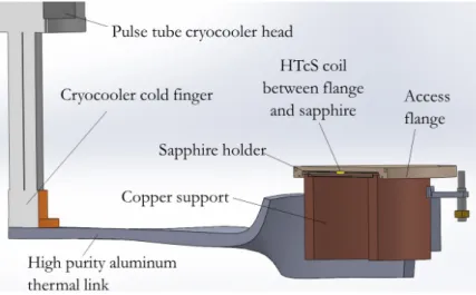
As already mentioned the HTcS coil is very sensitive to vibrations and cannot be too close to a metallic part due to electro-magnetic effects. This coil will be directly located on the sapphire cylindrical holder (λ=1000 W/m.K at 77 K [8]) as it is shown on the figure 5. The sapphire holder has a diameter of 150 mm and a height less than 10 mm. It is supported by a large hollow cylindrical copper piece that will allow transferring the heat and keep the coil below few mm from the access flange. The copper cylindrical piece is in Cu-OF (RRR=80) which has a rather good thermal conductivity of 531 W/m.K at 77 K and 1.5 T [8]. It is 70 mm high and the maximum thickness is 15 mm and it is attached on its periphery to the cryostat through polymers hooking tabs that are fixed on glass fiber rods tight on the flat upper part. This design, especially the complex shape of the copper piece, ensure that no metallic part is within the necessary distance of 100 mm from the coil to avoid electro-magnetic perturbations (cf. Fig. 6).
6
thermal contact. The length of the aluminum part is 750 mm and will be constructed from 6N aluminum (λ=424 W/m.K at 77 K and 1.5 T [8]).
Figure 5. 3D view of the different thermal links from the cryocooler to the HTcS coil. The hardest constraint in the thermal design is to limit the heat flow coming from the external side of the cryostat, which is at room temperature, to the HTcS coil. The MRI measurements impose that the distance between the biological sample and the coil be only a couple of millimeters. The optimal design must minimize the heat flow, keep the coil at 60 K, allow enough vacuum space between coil and the internal part of the cryostat, and limit the mechanical deformation of the access flange. This has been possible in reducing the overall thermal conductance between the access flange and the circular sapphire plate by reducing the contact area. The figure 6 shows the thermal computations carried on the HTcS holder. The computations have been conducted with the constraint to keep the HTcS coil, located on top of the sapphire support, at 60 K. The thermal model includes the heat transfers through conduction, convection and radiation for the domains presented in the figure 6 when applicable. The heat transfer on the external part of the access flange has been only modeled by a convective heat transfer boundary condition taking into account the convective air flow since radiation is negligible. The room temperature was set to 300 K and the heat transfer coefficient to h=10 W/m2.K. This value is representative of a low air flow that is maintained in the room bore of the MRI scanner. For the modeling of the internal part (under vacuum), only conduction and radiation were implemented. For the radiation computation part, emissivities of 0.95 and 0.48 were taken for the access flange (Peek) [9] and the sapphire [10] respectively. The thermal contact between the different parts was assumed to be perfect, i.e. with no thermal contact resistance. This is an optimistic assumption but the maximum power of the selected cryocooler is three times higher to overcome this assumption. The temperature of the external sides of the copper part in contact with the aluminum part was left without constraint conditions so it can adjust freely. The temperature distribution given in the figure 6 has been obtained for a heat flux of 9.2 W. The radiation heat transfer contribute to 5 W and the conduction to 4.2 W.
7
1234567890
CEC 2017 IOP Publishing
IOP Conf. Series: Materials Science and Engineering 278 (2017) 012122 doi:10.1088/1757-899X/278/1/012122
Figure 6. Thermal computation of the overall HTcS coil holders.
5. Conclusions
The overall cryogenic design of a non-magnetic cryostat to perform micro magnetic resonance imaging in medical environment is presented. A cryogen-free design was chosen and allows maintaining the HTcS probe at a temperature of 60 K with less then 10 W. This cryostat is currently under construction to be tested before the end of the year. Some improvements are already under considerations to design and construct a second version of that apparatus. The main driving idea is to reduce the weight of the cryostat to have an apparatus as much mobile as possible. One way to go is to replace the material of the cylindrical vessel by PEEK. This should reduce the weight by a factor of two. For that matter some R&D are undertaken to improve the PEEK weldability. The second idea would be to replace the aluminum thermal link by pulsating heat pipes. This gain in weight has not been really evaluated but this light two-phase thermal link is very promising for cryogenic applications.
Acknowledgments
This work was supported by the French National Research Agency under the grant number ANR14CE17-0003-01.
References
[1] Gonord P, Kan S and Leroy-Willig A 1988 Magnetic Resonance in Medicine 6 353–358 ISSN 1522-2594 [2] Poirier-Quinot M, Ginefri J C, Girard O, Robert P and Darrasse L 2008 Magnetic Resonance in Medicine
60 917–927
[3] Suprasense URL http://www.agence-nationale-recherche.fr/?Project=ANR-14-CE17-0003 [4] Song Y, Four A and Baudouy B 2013 International Journal of Heat and Mass Transfer 66 64 – 71 [5] Song Y, Four A and Baudouy B 2014 AIP Conference Proceedings 1573 1483–1489
[6] Achieva 1.5 T URL http://www.usa.philips.com/healthcare
[7] Victrex URL https://www.victrex.com/fr/products/victrex-peek-polymers [8] Crycomp version 3.06, cryodata inc. Florence SC, USA
[9] Esser B and G¨ulhan A 2008 Qualification of Active Cooling Concepts in Ground Facilities (Berlin, Heidelberg: Springer Berlin Heidelberg) pp 104–131 URL http://dx.doi.org/10.1007/978-3-540-77819-6_7 [10] Wittenberg A M 1965 J. Opt. Soc. Am. 55 432–435