DESIGN OF A ROBOTIC END-EFFECTOR FOR AUTOMATED BOLTING
by
David L. Dean, Jr. B.S. Mechanical Engineering, North Carolina State University
(1983)
SUBMITTED TO THE DEPARTMENT OF MECHANICAL ENGINEERING IN PARTIAL FULFULLMENT OF THE REQUIREMENTS FOR
THE DEGREE OF MASTER OF SCIENCE IN MECHANICAL ENGINEERING
at the
MASSACHUSETTS INSTITUTE OF TECHNOLOGY May 1983
Copyright 1985 Massachusetts Institute of Technology
Signature redacted
Signature
of Author _I_?#-_ --- _Department of Mechanical Engineering May 10, 1985
Signature redacted
Certified by
Profess r Neville Hogan
Signature
redactedsis
Accepted by
Professor Ain A. Sonin Chairman, Department Committee
MASSACHUSETTS INSTITUTE OF TECHNOLOGY
JUL22 1985
DESIGN OF A ROBOTIC END-EFFECTOR FOR AUTOMATED BOLTING
by
DAVID L. DEAN, JR.
Submitted to the Department of Mechanical Engineering on May 10,1985 in partial fulfillment of the requirements for the Degree of Master of Science in
Mechanical Engineering
ABSTRACT
The goal of this thesis is to expand the manufacturing and assembling capabilites of today's robots. Most industrial robots are restricted to tasks that involve little interaction between the manipulator and the workpiece. In contrast, in this project interaction forces will be deliberately generated and used. Specifically, the object of this thesis is to demonstrate that the careful use of interaction forces generated between robot and workpiece can facilitate an assembly task, putting a bolt in a threaded hole.
A design for a special-purpose robotic end-effector for bolting is presented. A feature of this tool is its deliberate use of
interaction forces. An investigation of the bolting process is presented, showing that cross-threading can occur even when the
misalignment of bolt and hole is small. By using interaction forces to reduce misalignment of the parts to be assembled, this new tool will reduce the probability of cross-threading. The new tool design is evaluated by comparing it with an earlier prototype.
Thesis Supervisor: Neville Hogan
3
ACKNOWLEDGEMENTS
I was very fortunate to have Professor Neville Hogan as my thesis advisor. Particular thanks are due to Professor Hogan for the
instruction, patience and insight he gave throughout this design
project. I would like to also thank the grad students of 3-470: Theo, Jim, Jeff, John Tandler, John Schneiter, and especially Eric Vaaler for all the help he gave me on this design. Also a special thanks to Max Mendel and John Simon who kept me out of the right half plane in the late hours of the night.
I would also like to thank Mack and Nancy Isenhour for the love they have provided since I joined their family. A very special thanks to Mack for the long hours he spent doing all the mechanical drawings in this thesis.
A special thanks also to my sisters, Jackie, Lisa, Debbie, and to Lee, my brother-in-law, for their constant support while I have been in school. My parents also deserve much credit for all their love,
support and sacrifice during the course of my education. I would like to especially thank them for raising me in a Christain home and
instilling in me the iniative to succeed.
Also I would like to thank my wife for the love and support she has provided while I was at MIT. I would also like thank her for
typing this thesis. Finally, I would like to thank April Rene', our new baby girl for making all the struggles at MIT worthwhile.
4
5 TABLE OF CONTENTS Page ABSTRACT 2 ACKNOWLEDGEMENTS 3 DEDICATION 4 TABLE OF CONTENTS 5 LIST OF FIGURES 7 LIST OF TABLES 9 I. INTRODUCTION 10
1.1 A New Approach to Assembly 10
1.2 Bolting Tool Requirements 11
1.3 Thesis Objective 14
1.4 A Summary of Following Chapters 14
II. EVALUATION OF MARK I 15
2.1 Mark I Bolting Sequence 15
2.1.1 Bolting Tool Delivery 15
2.1.2 Clockwise Rotation 17 2.1.3 Downward Translation (#1) 17 2.1.4 Bolt Retention 17 2.1.5 Upward Translation 18 2.1.6 Counter-Clockwise Rotation 18 2.1.7 Downward Translation (#2) 18 2.1.8 Bolt Rotation 19
2.2 Assets of the Mark I Tool 19
2.3 Weaknesses of the Mark I Tool 19
III. BOLTING INVESTIGATION 21
3.1 Prior Work 21
3.2 Experimental Investigation 22
3.2.1 Translational Experiment Procedure 24
3.2.2 Rotational Experiment Procedure 25
3.2.3 Diametral Clearance Measurement 25
3.3 Experimental Results 26
3.3.1 Translational Misalignment 26
3.3.2 Angular Misalignment 28
3.3.3 Cross-threading Versus Tolerance Class 32
6
Page
IV. DESIGN ISSUES 36
4.1 Parallel Cross-threading 36
4.2 Starting Tool Versus Tightening Tool 37
4.3 Anchoring 39
4.4 Dynamic Loading of the Tool 39
4.5 Summary 40
V. DESIGN PROPOSALS 42
5.1 The Anchoring System 42
5.2 The Delivery System 46
5.3 The Probe Locking System 55
5.4 Bolt Rotation System 58
5.5 The Modified RCC Design 58
VI. FINAL TOOL DESIGN 64
6.1 The Bolting Mechanism 64
6.1.1 The Probe Cartridge 64
6.1.2 The Bolt Cartridge 74
6.1.3 The Delivery System 74
6.1.4 The Anchoring System 85
6.1.5 The Bolt Rotation System 85
6.2 The Modified RCC 90
VII. EVALUATION AND RECOMMENDATIONS 97
7.1 Evaluation of the Mark II Tool 97
7.1.1 Pre-bolt Delivery 99
7.1.2 Part and Tool Alignment 99
7.1.2.1 Probe Delivery 100
7.1.2.2 Probe Activation 100
7.1.2.3 Probe Entry 100
7.1.3 Tool Stabilization 102
7.1.4 Probe Removal and Bolt Delivery 103
7.1.5 Bolt Rotation 104
7.2 Strategy Review 104
7.3 Future Work 105
APPENDIX 107
7
LIST OF FIGURES
Figure Page
1.1 Schematic of a Specific Bolting Task 13
2.1 The Mark I Tool 16
3.1 Experimental Apparatus 23
3.2 Translational Misalignment 27
3.3 Tolerance Class for a 8M x 1.25 x 6H6h Nut and Bolt 33
4.1 Three Phases of the Bolting Process 38
5.1 Initial Anchor Design 44
5.2 Final Anchor Design 45
5.3 Possible Delivery Movement 47
5.4 Sliding Cartridge Design 48
5.5 Parallel Track Design 50
5.6 4-Bar Linkage Design 51
5.7 Probe Cartridge Trajectory 53
5.8 Bolt Cartridge Trajectory 54
5.9 A Wooden Model of the Mark II Tool 56
5.10 The Probe Cartridge 57
5.11 The Bolt Cartridge 59
5.12 Conceptual Kinematics of the RCC 61
5.13 First Modified RCC Design 62
6.1 Assembly Drawing of the Mark II Tool 66
6.2 Probe Cartridge Mount 67
6.3 Probe Cartridge Piston 68
6.4 Probe Cartridge Shaft 69
8
Figure Page
6.6 Epoxy Sleeve 71
6.7 Probe Cartridge Shell 72
6.8 Groove Details 73
6.9 Bolt Cartridge Mount 75
6.10 Bolt Cartridge Shaft 76
6.11 Bolt Cartridge Shell 77
6.12 Housing 79 6.13 Housing Bar 80 6.14 Actuator Mount 81 6.15 Links A and B 82 6.16 Rod Connectors 83 6.17 Shafts A-D 84 6.18 Damper Mount 86 6.19 Anchor 87 6.20 Anchor Stop 88 6.21 Motor Mount 89 6.22 Connecting Plate 91 6.23 Link "C" 92 6.24 Backplate 93
6.25 Roll Bearing Shaft 95
6.26 Roll Bearing Housing 96
9
LIST OF TABLES
Table Page
3.1 Lateral Misalignment Observations (Close Tolerance) 29 3.2 Lateral Misalignment Observations (Normal Tolerance) 30 3.3 Lateral Misalignment Observations (Loose Tolerance) 31
10
CHAPTER ONE INTRODUCTION
This thesis is part of a project designed to expand the manufacturing capabilities of today's robots. most industrial manipulators are restricted to tasks that involve little dynamic interaction between manipulator and workpiece. These tasks include spray painting, welding, pick and place tasks and tasks in unsafe environments. The exchange of energy between the robot an.d workpiece has usually been kept to a minimum due to alignment and accuracy
problems. For similar reasons, up until now, assembly tasks have been performed by hard automation or people. The thrust of this thesis is to demonstrate that an assembly task can be performed by manipulators with the careful use of interaction forces generated between robot and workpiece.
1.1 A New Approach to Assembly
A new approach to the assembly problem that focuses on the
interaction between manipulator and workpiece has been termed impedance control (3,4].
Mechanical
impedance is a generalization of mechanical stiffness which includes possible dynamic effects such as viscosity, inertia, etc. In more general terms, the impedance of the manipulator dictates how the manipulator will respond when displaced by anyworkpiece. Conversely, the admittance of the workpiece (the dual or inverse of impedance) dictates how it will respond when pushed upon by any manipulator. The control of the manipulator's impedance, and one motion variable (position, velocity, acceleration, etc.) at the point of interaction can dictate the behavior of both the manipulator and the
11
workpiece. For example, if a manipulator were approaching a rigidly held workpiece, the manipulator could change its impedance so that the contact between the robot and workpiece would not be a collision but a controlled connection.
The scope of the work presented here is a small part in the development of impedance control. The goal of this work is to
demonstrate that impedance control can facilitate industrial assembly. To achieve this goal, the assembly task of bolting was chosen, where an unthreaded or through part is fastened to a threaded part with a gasket possibly inserted between the two. An unmodified bolt will be used. The reason for choosing the bolting assembly problem is because bolting
is a widely used means of assembly.
This bolting operation will be performed using a specially designed bolting tool. It is the second attempt at such a tool and will therefore be appropriately labeled Mark II, with its predecessor being Mark I. [7] The bolting tool design presented here will be
mounted as the last link of a manipulator. A major feature of the tool is that it will brace against the workpiece while the bolting operation is being performed. It will be compliantly supported with an
adjustable impedance between the tool and manipulator. The compliance will allow the tool to align itself with respect to the workpiece and also allow the connection between tool and workpiece to be a controlled one. More specific requirements of the tool will be given later.
1.2 Bolting Tool Requirements
At the outset of this project, it was decided that the bolting tool should be designed with a specific bolting operation in mind to
12
highlight the practicality of an impedance controlled device. The task is represented in Figure 1.1 where a manipulator is delivering a
bolting tool whose function is to fasten the headcover of an engine to the engine block with a gasket included.
As shown, the bolts to the headcover have limited vertical access, therefore the manipulator must approach the hole from the side. Note also that the headcover has eight fastening locations, four on each side that must be bolted in a particular sequence. Usually all eight bolts would be started to align the headcover, then they would all be pretightened to ensure the gasket is sealed with equal pressure at all points, and then the bolts would be tightened to their final torque.
More specifically the bolting tool has to meet several
requirements. The tool will be mounted as an end-effector on a robot comparable to a General Electric P50. The tool must accomodate the workpiece and compensate for the misalignments, both angular and
translational, of the endpoint location of the manipulator. The tool will be designed as a special purpose device for threading M8 metric bolts. It is also assumed that the vertical access to the threaded hole is limited. Ideally, the tool should be self-contained and
modular; for example, it should be mountable on any robot of comparable size and should require no feedback to the manipulator for
repositioning purposes during the bolting process. The robot's only function is the delivery of the tool to the threaded hole location within its own specified accuracy tolerances.
13
headcover
bolting
location
gasket
engine block
Figure 1.1 Schematic of a Specific Bolting Task
14
1.3 Thesis Objective
The objective of this thesis is to demonstrate the feasibility of impedance controlled assembly machines through the specific design of a self-aligning end-effector with variable impedance that will start M8 bolts.
1.4 A Summary of Following Chapters
The next chapter is an evaluation of the first bolting tool designed, the Mark I. In Chapter Three the results of a bolting investigation are discussed. In Chapter Four design issues that
evolved during the design course are discussed. In Chapter Five design proposals for a new bolting tool are discussed and, then in Chapter Six a final tool design is presented. In the final chapter, an evaluation based on the first bolting tool is done and recommendations for further work in this area are given.
15
CHAPTER TWO EVALUATION OF MARK I
As mentioned previously, the bolting tool design presented here is the second generation tool in this project. The first tool, Mark I (shown in Figure 2.1), was designed and built by R. Dirk Taylor. [7] This design was an excellent first prototype and provided much insight into the task of bolting and provided the author with a good base from which to begin his own design. Before evaluating the Mark I tool's performance, a complete sequencing routine is provided.
2.1 Mark I Bolting Sequence
The bolting sequence for the Mark I has eight operational steps. Local (x,y,z) and ground (X,Y,Z) coordinate systems are shown in
Figure 2.1 to facilitate explanations. Rotation about the x-axis, the
o direction will be referred to as the roll of the tool and rotation about the y-axis, the 0 direction will be considered the pitch of the tool. To make the system complete, rotation about the z-axis, the T direction will be considered the yaw of the tool. Finally, any parts mentioned in the explanation will be followed by a number in
parenthesis to make cross-referencing with Figure 2.1 easier. 2.1.1 Bolting Tool Delivery
A manipulator given the coordinates of the threaded hole with respect to the ground reference frame delivers the Mark I tool to the workpiece. In the process of the tool traveling to the hole location, a bolt is fed through the bolt delivery tube (4) and falls into the bolt holding station (5). The anchor (10) is the first part of the tool to contact the workpiece. During this connection a rotational
1. Indexing Table 2. Pneumatic Nutrunner 3. Probe
4. Bolt Delivery Tube 5. Bolt Holding Station 6. Pneumatic Cylinder-Table Rotation 7. Pneumatic Cylinder-Table Elevation 8. Vertical Slide-Table Elevation 9. Bolt Retaining
Fingers-Pneumatic Actuation
16
Z
13
9 Z 10 .16*
X12
YWorkpiece
10.
Anchor
11. Floating Plate-Horizontal Compliance 12. FloatingBase-Rota tional Compliance 13. Backplate and
Slide-Vertical Compliance 14.
Spring-Vertical Compliance
15. Rotational Compliance Links 16. Horizontal
Compliance-Shear Pads
17
bearing in the rear of the tool (not shown) allows the tool to adjust its roll position and the four-bar linkage design (15) allows the tool
to adjust its pitch position. Therefore once the tool has contacted the workpiece securely, it has been aligned properly in both angular positions.
2.1.2 Clockwise Rotation
The next step in the bolting sequence is the clockwise rotation (negative T direction) of the indexing table about the z axis,
accomplished by the table rotation pneumatic cylinder (6). This step accomplishes two things. First, it moves the socket attached to the pneumatic nut-runner (6) over the bolt in the bolt holding station (5), and it also aligns the probe (3) over ,the threaded hole.
2.1.3 Downward Translation (#1)
The third step in the bolting sequence is the downward movement of the indexing table forced by the table elevation pneumatic cylinder (7). Due to this actuation the bolt is forced into the socket of the nut-runner (2) at the bolt holding station (5), and the probe (3) is
forced to align the through part and the gasket with the threaded hole. The probe also aligns the tool in both lateral x and y directions with respect to the workpiece. The shear pads (16) provide the tool with
the lateral compliance needed to adjust. Therefore at this point the tool is aligned in all directions, and the shear pads are in a stressed state.
2.1.4 Bolt Retention
The fourth step of the sequence involves retaining the bolt inside the socket. This task is accomplished by the use of the bolt retaining fingers (9) positioned directly under the nut-runner (12). The
18
fingers (9) are engaged using a small pneumatic cylinder (not shown). Therefore, at this point in the process, the probe (3) is still in the
threaded hole, and the bolt is locked into the socket by means of the bolt remaining fingers.
2.1.5 Upward Translation
The fifth step in the bolting sequence is the upward movement of the indexing table forced by the table elevation-pneumatic cylinder (7). Due to this actuation the bolt is lifted out of the bolt-holding station, and the probe is lifted out of the threaded and through parts. Since the probe (3) has been lifted out of the threaded hole, the
downward normal force due to the anchor (10) should keep the tool aligned.
2.1.6 Counter-Clockwise Rotation
The sixth step in the bolting sequence is the counter-clockwise rotation (positive
y
direction) of the indexing table about the z-axis, accomplished by the table-rotation pneumatic cylinder (6). These steps accomplish two things. It moves the probe (3) out of the way and moves the bolt into position over the threaded hole. At this point in the process, the tool is ready to begin the actual threading process. 2.1.7 Downward Translation (#2)The seventh step is the second of two downward movements of the indexing table forced by the table elevation cylinder (7). When the indexing table (1) reaches its lower limit, the bolt in the socket should be aligned with respect to the threaded hole and ready to be rotated. Note also that at this time in the process, a second bolt would be fed through and held at the bolt-holding station (5).
19
2.1.8 Bolt Rotation
The final step of the bolting sequence is when the bolt is actually rotated by the pneumatic nut-runner (2).
2.2 Assets of the Mark I Tool
The Mark I tool achieved many of the goals set forth in this
project. It proved the necessity of several critical components in the design. These components include the probe, the anchor and the Tool Impedance Isolator (TII), a modified form of the Remote Ce.nter of Compliance (RCC) [2]. The probe that the Mark I tool utilizes proved to be an effective means of mechanically referencing the threaded hole. The probe coupled with the TII required no feedback to the robot, one requirement set forth in the project. The probe used in the Mark I tool was only responsible for aligning the tool in the lateral x and y directions; yet, if desired it could also eliminate angular
misalignment.
Another successful component, the anchor, served two purposes in the Mark I design. It was responsible for aligning the tool in two angular directions (0 and ) and for providing mechanical interaction forces due to friction between the tool and the workpiece. Finally, the TII design used to kinematically locate the center of rotation of the tool at the center of the anchor allowed the probe to be inserted without jamming or wedging.
2.3 Weaknesses of the Mark II Tool
As shown in Figure 2.1, the bolt-driver dictates the shape and size of the tool. If it were eliminated the tool could be much smaller and lighter, thereby ameliorating problems due to build-up of backlash.
20
Secondly, the Mark I's anchor assumes an ideal workpiece, one that has a generous flat surface surrounding the threaded hole, located on an edge. Thirdly, the four-bar linkage providing the Mark I rotational
accomodation possesses no springlike members to provide it with an equilibrium position. As a result the tool introduces a substantial
uncertainty in the location of the probe with respect to its nominal position determined by the robot. Fourthly, the Mark I tool does not
allow for bolting at an arbitrary distance from an edge. Fifthly, the tool allows for misalignment along the axis of the bolt. This is an unnecessary complication. Finally, the Mark I tool adjusts itself by placing the anchor on the workpiece first and then inserting a probe. The subsequent removal of the probe may allow misalignment to reappear. To prevent this the probe should be inserted first to eliminate all misalignment. Then the tool should be braced with respect to the workpiece to preserve this alignment.
The evaluation of the Mark I tool was an important first step in the design procedure. By evaluating it, the author eliminated the possibility of duplicating his work and was able to begin his design on
a higher level. Finally, the Mark I tool brought the underlying problems in a bolting operation to the surface and singled out each
21
CHAPTER THREE
BOLTING INVESTIGATION
In order to develop a second prototype tool which was an
improvement over the Mark I tool, it was first necessary to establish some quantitative design specifications. For example, what is the maximum angular and translation misalignment the tool has to
accomodate? What is the magnitude of the angular and translational correction the tool must make? (i.e. what is the angular and
translational misalignment the bolting process can tolerate?) Should the bolt be stationary or moving on insertion? How does the tolerance class of bolt and hole influence the bolting process? How does the rigidity of the manipulator affect the bolting process? To address
these questions, the bolting process was investigated.
3.1 Prior Work
Part of the bolting investigation was an attempt to find reference material relevant to the bolting process. The material found was a short paper, "Reliable Automatic Starting of Threaded Parts," by a Russian author, I.E. Blaer [1], and an M.I.T. Bachelor's thesis by Paul Ranyak (6] who based most of his work on Blaer's paper. The central concern of both of these works is cross-threading.
Ranyak in his thesis described two types of cross-threading. The first type was angular cross-threading where one tries to start the bolt relative to the nut one full thread out of phase. To do this with an M8 nut and bolt, the bolt would have to be tilted at almost 15
degrees, unlikely in automated assembly. The second type of cross threading that Ranyak described was parallel cross-threading, where the
22
beginning threads of the bolt and hole overlap when contact is
initially made, and then are crushed together when rotation occurs. The beginning of the threads for both the bolt and hole must be in phase with each other for parallel cross-threading to occur. If they
are out of phase (e.g. by 180 degrees) parallel cross-threading will not occur.
In the design of the Mark I tool, the issue of cross-threading was also considered. Taylor [7] performed a series of experiments in which a metric M8 bolt was placed in the collet, and an M8 nut was clamped to the x-y table of a Bridgeport milling machine. In this apparatus
(which is almost perfectly rigid), it was determined that the bolt must be aligned angularly to within one degree and translationally to within .005" to guarantee successful thread starting. Note that in this
series of experiments, when the bolt first made contact with the nut, it was stationary.
3.2
Ecperimental
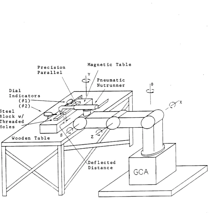
InvestigationTo provide a more realistic quantitative basis for the new design, and to familiarize the author with the bolting process, a short series of experiments were performed. The experimental apparatus shown in Figure 3.1 included a GCA manipulator with a pneumatic nut-runner mounted as its last link. M8 bolts were threaded into a one-inch block of steel that had several chamfered (590) and threaded holes. The steel block was placed on a magnetic chuck that was mounted on a sturdy wooden table as shown in Figure 3.1. The position of the bolt relative to the hole was measured using a precision parallel block and dial indicators.
23
Precision
Magnetic Table
Parallel
SPneumaticNutrunner
Dial
Indicators(1
X
Steel
Block w/
Threaded
Holes
Wooden Table
DeflectedDistance
GCA
24
In the bolting experiments performed by Taylor, the bolt was not rotating when it initially made contact with the M8 nut, and the apparatus used was very stiff. In this investigation the opposite extremes were taken for comparison purposes; the bolt was rotating when it made contact with the threaded hole, and the manipulator used was very compliant when compared to other manipulators (such as the GE P50). The procedure for this investigation was divided into two parts - the first part was an experiment involving translational misalignment, and the second involved rotational misalignment.
3.2.1 Translational Experiment Procedure
The procedure for the translational experiment involved the
following steps. Note that this procedure was repeated on the same bolt until that bolt crossthreaded.
1. Take a new bolt and measure major diameter. 2. Insert into socket of nut-runner.
3. Step the GCA up to a position where the bolt is directly above the hole.
4. Slide the dial indicator (#1) over against the bolt-runner and zero it.
5. Turn on the bolt-driver.
6. Lower the spinning bolt into the hole.
7. Record the maximum and average deflection of the robot, using the .001 dial indicator (#1).
8. Return the GCA to the home position.
9. With the bolt in the threaded hole record the maximum
deflection of the head of the bolt in the +x and -x direction using a 0.0001" (#2) dial indicator. Call this deflection R.
25
10. Remove the bolt and record the number of revolutions required,
N.
11. Step the GCA back to the position nominally above the hole (as in step 3) and measure any residual deflection of the robot due to the bolting operation.
12. Misalign the threaded hole laterally by a known incremental amount and repeat steps 3-12 using the same bolt.
3.2.2 Rotational Experiment Procedure
The procedure for the angular experiment involved the following six steps. Note that it was carried out on a new bolt and hole each time.
1. Using a new bolt and threaded hole, thread the bolt up to five threads.
2. Record dimension R (step 9 in section 3.2.1) and remove the bolt.
3. Insert the same bolt into the socket of the nut-runner. 4. Step the GCA up to the position where the bolt is directly
above the hole.
5. Misalign the bolt angularly by rotating the axis of the manipulator (see Figure 3.1). measure this angular
misalignment to within .50 using an adjustable triangle. 6. Start the nut-runner. Lower the spinning bolt into the
threaded hole at constant velocity. 3.2.3 Diametral Clearance Measurement
An important parameter of the bolting process is the diametral clearance between bolt and threaded hole.
measuring
the diametral clearance is not trivial. An approximation was made by measuring the26
deflection at the head of the bolt (the recorded distance R) using a ten-thousandths inch dial indicator and recording the number of threads the bolt entered the hole (N). These numbers were then substituted into Equation 1 (which is based on simple geometry) to provide an estimation of the diametral clearance.
Diametral Clearance = sin
[tan
(1.826
-R. 1 .04921N (1)3.3 Experimental Results
The first concern of the experiments was to estimate the maximum angular and translational misalignment which could be tolerated without compromising the reliability of the bolting process.
3.3.1 translational Misalignment
Given a specified translational misalignment, first - will this misalignment error allow the bolt tip to seat in the threaded hole, and
second - will this misalignment error prompt cross-threading?
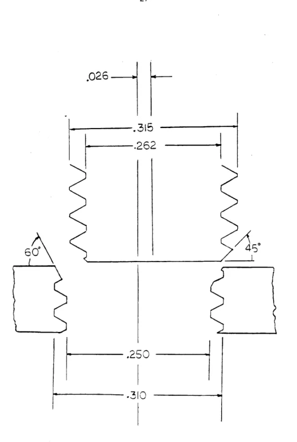
The answer to the first question depended strongly on whether the bolt was stationary or rotating when it first made contact with the workpiece. If the bolt was not rotating, then the problem became a simple chamfered peg-in-a-hole problem. As shown in Figure 3.2 the maximum tolerable misalignment (determined geometrically), to permit
successful assembly was .026".
If the bolt was rotating, determining the maximum tolerable misalignment which would allow the bolt to seat was much more
complicated. The first part of the bolting investigation addressed this issue. Experimentally the bolt could be misaligned by
27
.026--.315
.262
4 50
.250
.30-Figure 3.2 Translational Misalignment
28
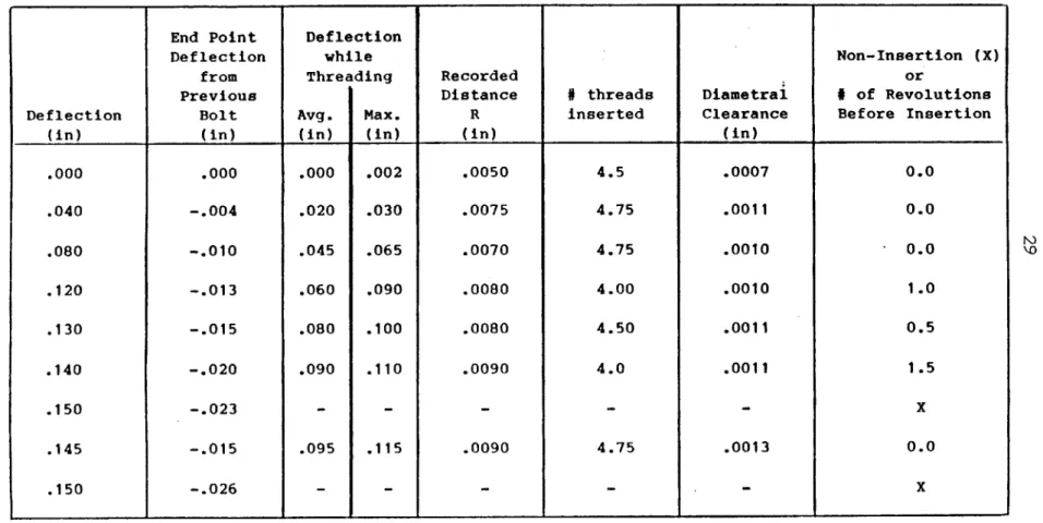
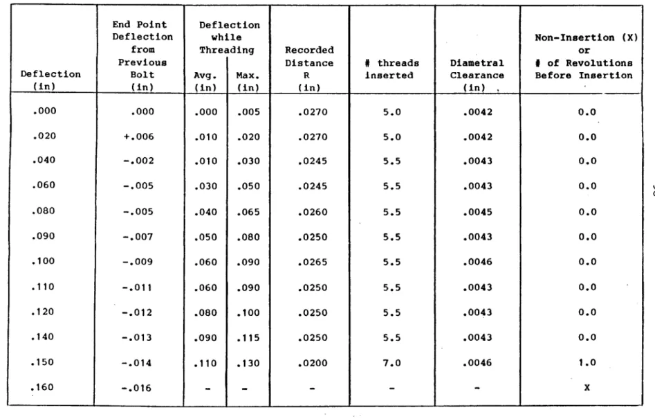
essentially by "walking" or spinning around the hole until it seated. The experimental observations are provided in Table 3.1, 3.2 and 3.3. The second question was, once the bolt tip was seated, would the specified translational misalignment cause the bolt to cross-thread? The first part of the investigation also addressed this question for three tolerance classes of bolts and threaded holes, though only for the case in which the rotating bolt approached the hole.
Experimentally, translational misalignments of up to .150" were tolerated without cross-threading. (see Tables 3.1, 3.2 and 3.3)
How can the bolting process tolerate such large misalignments? Unlike Taylor's experiments, in this work the manipulator was compliant and in addition the bolt head could swivel inside the socket of the nut-runner. (In Taylor's experiments it was clamped in a milling
chuck.) These two factors combined to allow the rotating bolt to tilt until its tip seated in the hole; then the bolt pulled the manipulator so as to reduce the translational misalignment. This deflection of the manipulator while threading was substantial (see Tables 3.1, 3.2 and 3.3) and effectively reduced the misalignment to between 0.020" and 0.040", which is within the diametral clearance between bolt and hole.
Note in passing that this experiment also provided data on the repeatability of the manipulator under these reacting conditions.
Errors of up to 0.026" were frequently observed. 3.3.2 Angular Misalignment
Given a specified angular misalignment, will this misalignment prompt cross-threading? In this part of the investigation, a new bolt and threaded hole was used in each trial and the bolt was rotating when it first made contact with threaded hole. The results are shown in
End Point Deflection
Deflection while Non-Insertion (X)
from Threading Recorded or
Previous
Distance
#
threads
Diametral
#
of Revolutions
Deflection Bolt Avg. Max. R inserted Clearance Before Insertion
(in) (in) (in) (in) (in) (in)
.000
.000
.000
.002
.0050
4.5
.0007
0.0
.040
-.004
.020
.030
.0075
4.75
.0011
0.0
.080
-.010
.045
.065
.0070
4.75
.0010
0.0
.120
-.013
.060
.090
.0080
4.00
.0010
1.0
.130
-.015
.080
.100
.0080
4.50
.0011
0.5
.140
-.020
.090
.110
.0090
4.0
.0011
1.5
.150 -.023
- - - - - X.145
-.015
.095
.115
.0090
4.75
.0013
0.0
.150 -.026
- - - - - XTable 3.1: Lateral Misalignment Observations (Close Tolerance)
End Point Deflection
Deflection while Non-Insertion (X)
from Threading Recorded or
Previous
Distance
#
threads
Diametral
# of Revolutions
Deflection Bolt Avg. Max. R inserted Clearance Before Insertion
(in) (in) (in) (in) (in) (in) I
.000
.000
.000
.005
.0270
5.0
.0042
0.0
.020
+.006
.010
.020
.0270
5.0
.0042
0.0
.040
-.002
.010
.030
.0245
5.5
.0043
0.0
.060
-.005
.030
.050
.0245
5.5
.0043
0.0
.080
-.005
.040
.065
.0260
5.5
.0045
0.0
.090
-.007
.050
.080
.0250
5.5
.0043
0.0
.100
-.009
.060
.090
.0265
5.5
.0046
0.0
.110
-.011
.060
.090
.0250
5.5
.0043
0.0
.120
-.012
.080
.100
.0250
5.5
.0043
0.0
.140
-.013
.090
.115
.0250
5.5
.0043
0.0
.150
-.014
.110
.130
.0200
7.0
.0046
1.0
.160 -. 016 - - - - - XTable 3.2: Lateral Misalignment Observations (Normal Tolerance)
End Point Deflection I
Deflection while Non-Insertion (X)
from Threading Recorded or
Previous
Distance
#
threads
Diametral
#
of Revolutions
Deflection Bolt Avg. Max. R inserted Clearance Before Insertion
(in) (in) (in) (in) (in) (in)
.000
.000
.000
.003
.0300
4.25
.0039
0.0
.040
-.002
.005
.007
.0300
4.00
.0036
0.0
.080
-.008
.015
.025
.0320
4.00
.0039
0.0
.120
-.018
.045
.055
.0270
4.25
.0035
0.0
.130
-.202
.050
.070
.0280
4.25
.0036
0.0
.140
-.024
.050
.070
.0290
4.25
.0037
0.0
.150 -.025
.055 .080 .0300 3 .0026 1.0 .160 -. 026j
- - - --X
.155
-.020
.065
.085
.0350
3.5
.0036
1.5
32
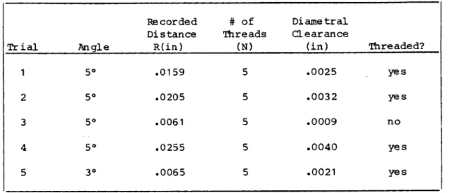
Table 3.4. Even given these few observations, it is clear that the maximum tolerable angular misalignment is 30 or even less. Note that
this is almost an order of magnitude less than the angular misalignment corresponding to angular cross-threading (see Section 3.1).
Recorded # of Diametral Distance Threads Clearance
Trial Angle R(in) (N) (in) Threaded?
1 50 .0159 5 .0025 yes
2 50 .0205 5 .0032 yes
3 50 .0061 5 .0009 no
4 50 .0255 5 .0040 yes
5 30 .0065 5 .0021 yes
Table 3.4: Angular Misalignment Observation
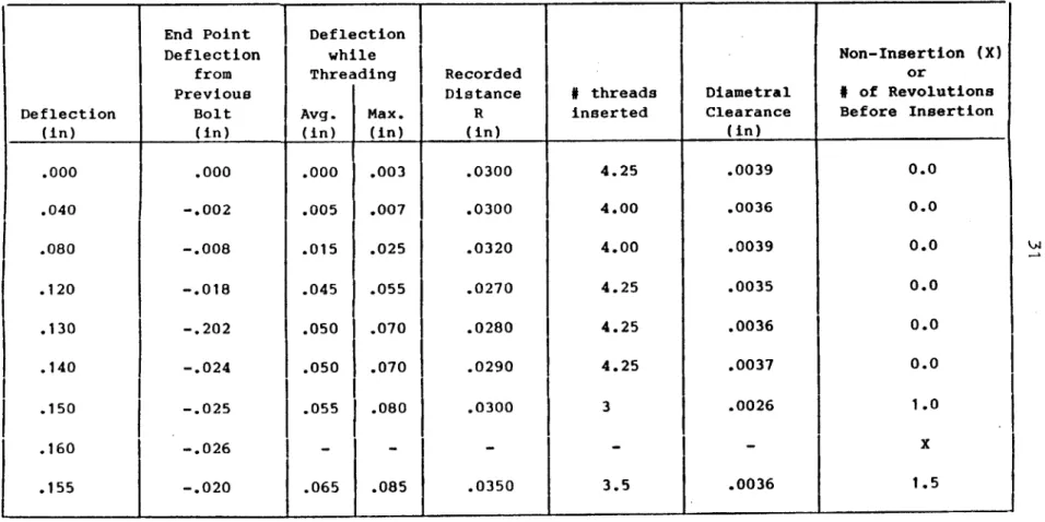
3.3.3 Cross-threading Versus Tolerance Class
From mechanical considerations it is clear that the likelihood of cross-threading may depend on the diametral clearance between bolt and hole. Diametral clearance may be determined from the tolerance class of the bolt and hole. The tolerance class for a standard M8 bolt and nut is 8M x 1.25 x 6H6h where "6H" and "6h" designate the tolerance class for the nut and bolt respectively. Because data could not be found specifying the tolerances on drilled and tapped holes it was assumed that the tolerance class for an M8 nut was the same for an M8 tapped and threaded hole. As shown in Figure 3.3, this tolerance class of nut and bolt could provide a tight fit of .000" diametral clearance and on the other extreme a loose fit of .0108" diametral clearance. (5]
33
Basic
Size
A
es
es
e
External Thi
(bolts)
Internal Threads
(nuts)
G
es=OEI=OH
T .0066"1
S.0042"
ma
x. tolerance for pitch
eads
diameters
where:
EI = low er deviation of nut thread
es
=
upper deviation of bolt thread
Figure 3.3 Tolerance Class for a 8M x 1.25 x 6H6h Nut and Bolt
It is not clear that a bolt and nut with 0.000" diametral clearance can be assembled. After consulting with Bossard
International, a leading manufacturer of metric fasteners, it was learned that bolts and nuts are produced in large batches, and with every batch a quality control analysis is performed that provides an estimate of the range of tolerances for that particular batch. For any given batch of nuts and bolts, the clearances would be expected to be distributed statistically between the two specified extremes. If the distribution were Gaussian and it is assumed that 99% of the batch have clearances between the limits of
0.000"
and 0.0108", then the standard deviation would be 0.0018"; therefore 95% of the batch would have clearances between 0.0018" and 0.009". Clearly, a design which accomodates the full clearance range of 0.000" to 0.0108" would be overly conservative.34
What clearance range is likely to be encountered in practice? The diametral clearance between the threaded hole and bolt was measured
(using the method previously outlined) in both parts of the experiment. In the investigation of translational misalignment, no reliable
conclusions about the influence of diametral clearance on cross-threading can be drawn from the data because the same bolt was used repeatedly (almost ten times) until the bolt cross-threaded. The repetitious use of a bolt in this manner is not representative of manufacturing processes in which a new bolt and threaded hole are used every time. In the investigation of angular misalignment, a new bolt and threaded hole were used for every trial. Diametral clearances as
low as 0.0008" were observed. Furthermore, it is clear that low diametral clearance can promote cross-threading. At 50 one bolt
cross-threaded with a diametral clearance of .0008", while three other bolts with clearances of .0025", .0032" and .0040" did not.
Because angular cross-threading, in which the bolt and nut are one full thread out of phase would require 150 of angular misalignment, the observation of cross-threading at 50 is probably due to a different
phenomenon, most likely that which governs parallel cross-threading. However, in our experiments parallel cross-threading was not observed when bolt and hole were perfectly aligned.
3.4 Summary
Because of the difficulty of duplicating a manufacturing process in a laboratory environment, the experimental results reported here should be interpreted with caution. However, they provide a basis for establishing design specifications for the Mark II tool. The data
35
indicate that cross-threading is more likely to occur when the
diametral clearance is small, and they also indicate that to eliminate cross-threading the tool should align the bolt and threaded hole to within at least 30 of perfect angular alignment and to within at least
0.026" of perfect translational alignment; closer alignments will probably yield better performance.
Finally, what is the maximum angular and translational
misalignment (due e.g. to robot or sensor inaccuracies) the tool must accomodate? No experimental procedure to determine these numbers was evident. From anecdotal observations, angular errors greater than 70 are unlikely. Using a probe to find the hole, translational errors of half a hole diameter, 0.165", are easily accomodated.
36
CHAPTER FOUR DESIGN ISSUES
At this point in the design process several issues had become clear. These issues were addressed and resolved before specific
proposals were considered for the new bolting tool design. Once these issues were resolved, a new set of tool requirements were outlined and included as a summary to this chapter.
4.1 Parallel Cross-threading
The first issue (discussed in the last chapter) is the problem of parallel cross-threading which may occur even when the axis of the bolt
and threaded hole are perfectly aligned. It occurs when the starting threads of the bolt and hole line up with each other as the bolt makes contact with the threaded hole. The weakened sections of the starting threads are then twisted into each other when rotation occurs. This effect is accented by the 450 and 600 chamfers of the bolt and threaded hole respectively.
A solution to the problem of parallel cross-threading is
"f reverse-threading" - to reverse the normal direction of rotation of
the bolt until the ends of the helical threads cross; then the starting thread of the bolt will fall one thread in depth onto a full thread section of the threaded hole. At this point the rotation of the bolt should be reversed and the bolt threaded. This strategy of reverse threading will ensure that the starting thread of the nut will be about 1800 out of phase with the starting thread of the bolt, thereby
37
In the investigation presented in Chapter Three, parallel
cross-threading was not observed when bolt and hole were coaxial, and it is unclear how large a problem it represents. Therefore, the Mark II tool will be designed to accomodate the strategy of reverse
threading; however, the strategy should not be employed until the tool has been tested in a manufacturing environment and the need for reverse
threading has been determined.
4.2 Starting Tool Versus Tightening Tool
The second issue is whether to separate the bolting process into two different processes using different tools. There are many
advantages to this strategy. Discussion with several graduate students at M.I.T. who have worked in manufacturing and assembly environments indicated that many U.S. companies use commercially available tools to run and tighten bolts to prescribed torques, but few companies start bolts automatically.
Secondly, a nut-runner which must generate the high torques needed for tightening will be heavy and bulky. This was mentioned previously in the evaluation of the Mark I tool as it was primarily responsible for its size, weight and kinematic design of that tool. In contrast only low torque is required for starting a bolt. Thirdly, the
tolerances required to start a bolt are much easier to achieve with a light dexterous tool. Also with a bolt already started, considerable clearance can be tolerated between the bolt head and the socket of a tightening tool.
Bolting may be described as having three different phases: the starting phase, the running phase and the tightening phase. All of
38
these are illustrated in Figure 4.1. To help decide this second
issue, the following aspects of the bolting process were categorized as part of the starting and running (S) or tightening (T) process or both (ST).
T
TI
req
"---~--acceptable
bolt too large run
severely damaged threads
Ttest -
-damaged starting threids
e
Starting Running Phase Tightening
Phase Phase
where: - Treg is the prescribed torque requirement of the bolt
- Ttest is the cutoff torque for threads that may present a problem
Figure 4.1 Three Phases of the Bolting Process The tool design issues:
1. (S,T): Speed of the whole process and how the total process time is distributed among the operations
2. (S):
Reliability
of the process3. (S): Ability to accomodate normal production tolerances 4. (S,T):
Recoverability
of the process (trade-off withreliability)
5. (S): Alignment of through and threaded hole 6. (S,T): Minimal access space (included in design)
7. (S): Detect incorrect assembly components (no gasket, wrong bolt, no gasket hole, no threads in hole or on bolt) 8. (T): Controlled axial loading
39
9. (S): Jamming/cross-threading
10. (S,T): Sensing and control requirements: a. Force
b.
Torque
c.
Displacement
d. Angular Displacement
Of these 10 items, 9 may be addressed in the starting and running phases, while only 5 involve the tightening phase. Therefore the Mark
II too will only perform the tightening and running phases of the process.
4.3 Anchoring
Another issue derived from the evaluation of the Mark I tool was the anchoring problem. Given a random set of workpieces with M8 threaded holes in various places, the only area on which to anchor common to all threaded holes is the small amount of flat area
surrounding the threaded hole. This area must be able to accomodate an M8 socket wrench and is perpendicular to the axis of the threaded hole. As an M8 socket wrench is approximately 1" in diameter, the bolting tool's anchor should only require at most a circular area of 1 inch in diameter on which to stabilize the bolting tool.
4.4 Dynamic Loading of the Tool
A final issue that was also derived from the evaluation of the Mark I tool was the problem of dynamic loading of the bolting tool during the steps of its operation. A fundamental aspect of the bolting
tool design was the fact that it used the threaded hole itself to align the bolting tool with respect to the workpiece. This alignment was
40
performed by the probe. Given this choice, the probe has to be removed before the bolt can be threaded.
The problem arises when the probe has been removed and the bolt is to be moved into place. The tool has been stabilized at this point in the process by a downward vertical force which creates a lateral
frictional force. Excessive dynamic loading due to abrupt acceleration or deceleration during this movement can overcome this stabilizing
force and cause the tool to return to its original misaligned position. This problem was observed in the Mark I design which used an indexing table and an attached pneumatic nut-runner (see Figure 2.1). The pneumatic nut-runner had sufficient mass to cause the tool to misalign due to inertial forces generated during its movement.
The solution to this problem includes two parts. First of all, the net force of the moving probe or bolt should be directed downward if possible because the tool is essentially rigid in the z-direction. This movement should not, if possible, direct forces in the x or y directions or the
e
and directions because the tool is compliant in these directions. Secondly, if the movement of the probe and bolt does direct forces in these directions, then a spring or damper element should be used to absorb the energy of this movement without generating excessive inertial forces.4.5 Summary
From consideration of these design issues and previous requirements, the new bolting tool, the Mark II, should:
1. start M-8 metric bolts with the bolts fed to the tool directly.
41
2. have as low a profile as possible to meet its limited vertical access requirement.
3. use a probe as a mechanical reference between tool and
threaded hole to align them to within at least 30 and .026". 4. accomodate initial misalignments of 70 and 0.165".
5. utilize an anchor to generate interference forces between manipulator and workpiece. The anchor will be restricted to rest on the 1" diameter area immediately surrounding the bolt head.
6. utilize the strategy of "reverse threading" to prevent
parallel cross-threading if this strategy is found necessary. 7. utilize springs and dampers to absorb the energy of moving
42
CHAPTER FIVE DESIGN PROPOSALS
This chapter presents some initial designs proposed for the Mark II tool. As in most design projects, ideas were not generated in any logical fashion but are presented here in a step by step fashion
building on the few known details of the design that were derived from the evaluation of the Mark I tool. The design proposals were broken down into these five systems: the Anchoring System, the Delivery System, the Probe Activation System, the Bolt Rotation System and the Modified RCC Design. (Taylor's Tool Impedance Isolator)
5.1 The Anchoring System
The purpose of the anchoring system is to purposefully generate interference forces between the workpiece and the manipulator to stabilize the new position of the tool generated when the probe was inserted. The anchor must counter-balance the forces generated by the deflection of the spring elements in the modified RCC. Therefore the anchor must be able to support forces in the x and y directions and moments about the 0 and directions.
The physical requirements of the anchor were outlined at the end of Chapter Four. The only surface area that the anchor can reliably utilize is the area immediately surrounding the threaded hole. This is
the only surface that is guaranteed perpendicular to the axis of the hole. The second physical requirement is to design the anchor so that it is the lowest point on the tool. This prevents the tool from being restricted to bolting on edges only.
43
In the first design (shown in Figure 5.1) the anchor is a cylindrical sleeve driven by two pneumatic actuators. To meet the limited vertical access requirements a constrained flexible drive
(similar to a bicycle brake cable) connects the two. There are several positive features of this design. First of all, it only requires the
surrounding area of the threaded hole as specified. The second
positive characteristic of the design is its use of cylindrical shapes, and this prompted the idea that the probe and bolt could be cylindrical cartridges which are loaded into the sleeve-like anchor. The biggest advantage to this approach is the fact that the anchor is never moved once the hole-is located. To accomplish this the anchor would first be loaded with the probe cartridge and then this assembly inserted into the hole.
Once
the hole was located the probe would be removed leaving the anchor in contact with the workpiece at the same position. The bolt cartridge is then inserted into the sleeve.A negative aspect of this proposal is its use of two actuators in such a limited space. This lead to the second design (which was
eventually adopted) in Figure 5.2. The anchor, as shown is compliantly supported in the z-direction by springs. In this design the
manipulator forces the anchor against the workpiece; the resulting deflection of the springs generates the needed force in the z-direction without the use of actuators.
The cylindrical anchor generated the idea of using identical cartridges for the probe and the bolt. The need then arose for some means of delivering the bolt and probe cartridges (respectively) to the center of the anchor.
44
pneumatic
actuators
flexible drive
ciI
concentric
sleeve
anchor
45
housing
anchor
stop
z-compliance elements
(extension springs)
anchor
46
5.2 The Delivery System
The purpose of the delivery system is the transportation of the bolt and probe from their resting place in the tool to the center of the anchor. This transportation involves four phases - two for each cartridge. The two critical phases are the removal of the probe and the delivery of the bolt. Dynamic loading of the tool during these two phases determines whether the tool will retain its corrected position.
The delivery system should have as low a profile as possible. There are several ways the bolt and probe cartridges could be delivered
to the anchor location as shown in Figure 5.3. The design task is to implement one of these possibilities in as little space as possible. Another requirement for both cartridges is that the delivery system
should transport the cartridge to the anchor, and at that point the cartridge should be in a perfectly vertical position. Furthermore, about the last quarter inch of this travel should be in the vertical
direction to accomodate the deflection of the anchor without binding or jamming. A further requirement for the bolt cartridge delivery system is that it should permit the bolt to be loaded into it at some point.
The first design considered (shown in Figure 5.4) was the Sliding Cartridge Design. This design involved mounting the two cartridges in a V-shaped track and then loading them into the anchor sleeve. The biggest advantage of this approach is its low profile. Given the size of an M8 bolt the delivery system could not be much smaller. However, there are several problems with this design. The first problem is the fact that it requires two actuators to deliver the cartridges
translationally and a third actuator to force it downward. Interfacing the cartridges with the anchor sleeve also presents a design problem.
47
(a)
If
(b)
(c)
(2 stage)
(d)
_
_
Figure 5.3 Possible Delivery Movements
(2 stage)
(1
stage)
48
pneumatic actuator
(vertical travel)
V-shaped housing
bolt cartridge
probe cartridge
pneumatic actuator
(horizontal travel)
49
Therefore another design was pursued employing a different means of transporting the cartridges.
The second design considered (shown in Figure 5.5) was the Parallel Track Design. Two parallel tracks are mounted side-by-side. One track is designed for the bolt cartridge and the other for the probe cartridge. A pneumatic actuator drives each cartridge along its path until it is seated in the anchor. There were several advantages to this design. First of all the way the track is designed allows the bolt cartridge to turn up so that a bolt may be dropped into it head first - one of the requirements for the bolting tool. The second advantage to this design is the straight line travel of the cartridges at the tip of the tool. The biggest and most overwhelming problem is the design of the track for the cartridges to run along. The straight line travel at the end of the track could cause the cartridge to jam when the probe is to be pulled from the threaded hole. Given these complications, another alternative was sought, one which would provide the horizontal and vertical motion in one movement, as this design did, but one that was easier to implement.
A design that provides the same type of movement is the 4-Bar Linkage Design. It was eventually adopted in the Mark II tool. The 4-Bar Linkage Design shown in Figure 5.6 utilizes two small 4-bar linkages. The linkage should be mounted in a V-shaped housing so that the coupler of the linkage, or the cartridge, has the same final
position at the center of the anchor, similar to the parallel truck design.
There are many advantages to a 4-bar linkage delivery system. Similar to the last design, the motion of the bolt cartridge linkage
50
pneumatic
actuators
cartridge track
probe cartridge
bolt cartridge
anchor
51
cartridge
links A and B
housing
angle
housing
52
allowed the cartridge to be turned upward to accept a bolt head first. A second advantage was the compactness of the entire system and the
fact that it met the requirement for low profile to a reasonable degree. A third advantage of the design is its symmetry. If the two linkages are designed identically then the accuracy with which the probe is removed and the bolt delivered should be within a few
thousandths of an inch, with the use of precision bearings. The biggest advantage to the system is the fact that it is implementable without difficulty.
To implement this design for the delivery system it was necessary to locate the pivot point for the linkage given a desired trajectory of the cartridge. Using a simulation package, DRAM (Dynamic Response of Articulating Machinery), the pivot points were located to within
.001" at positions that would allow the bolt cartridge to be turned upward at the end of the trajectory and vertically downwards at the anchor position, as shown in Figure 5.7. The probe's trajectory was identical to the bolt cartridge's except its path was shortened to stop with the probe in the horizontal position, because, unlike the bolt cartridge, it did not need to be loaded but only to be removed from the bolt cartridge's path as shown in Figure 5.8. A key feature of this design is that over the final 1/4 inch of travel, the deviation of the cartridge from a vertical path is within 0.003". This is clearly seen in the first two frames of Figures 5.7 and 5.8 which are drawn with the positions of the cartridge about 1/4" apart.
The minimum angle between the vertical rises of the housing that would accomodate both cartridges without the two colliding was
53
probe cartridge
pneumatic
actuator
mo
I1
lousing
Probe Cartridge Trajectory
54
bolt cartridge
p
a
neumatic
otuator
2ousing
Bolt Cartridge Trajectory Figure 5.8