UNIVERSITÉ DE MONTRÉAL
DESIGN OF A GRASPING AND MACHINING END EFFECTOR FOR THIN ALUMINUM PANEL
APPLE MAHMUD
DÉPARTEMENT DE GÉNIE MÉCANIQUE ÉCOLE POLYTECHNIQUE DE MONTRÉAL
THÈSE PRÉSENTÉE EN VUE DE L’OBTENTION DU DIPLÔME DE PHILOSOPHIAE DOCTOR
(GÉNIE MÉCANIQUE) JUILLET 2015 © Apple Mahmud, 2015.
ii
UNIVERSITÉ DE MONTRÉAL
ÉCOLE POLYTECHNIQUE DE MONTRÉAL
Cette thèse intitulée :
DESIGN OF A GRASPING AND MACHINING END EFFECTOR FOR THIN ALUMINUM PANEL
présentée par : MAHMUD Apple
en vue de l’obtention du diplôme de : Philosophiae Doctor a été dûment acceptée par le jury d’examen constitué de :
M. BALAZINSKI Marek, Docteur ès Sciences, président M. MAYER René, Ph. D., membre et directeur de recherche M. BARON Luc, Ph. D., membre et codirecteur de recherche M. ACHICHE Sofiane, Ph. D., membre
DEDICATION
iv
ACKNOWLEDGEMENTS
I would like to express my deepest gratitude to my research supervisor Prof. Rene Mayer for extensive support, excellent guidance and warm encouragement during my research as well as for the trust he placed in me to work in my own way the lessons I learned from each of you which will remain useful for a lifetime. In addition to his help in writing the articles, he has always given very generously his time to discuss various aspects of this project. Special thanks to my co-director Prof. Luc Baron who has given very precious advices during this project.
I would like to thank NSERC for financial support of this project. I would also like to thank my friends, my colleagues and other members of CRIAQ 412 research team from bombardier who helped me during this study. Special thanks to Jean-François Lalonde and Benjamin Larregain from Bombardier Aerospace.
Technical guidance and instrumental help from Mathieu Côté and Christian Piette on behalf of Olympus NDT Canada Inc was tremendous.
I wish to express my gratitude to all secretaries of Department de Génie Mécanique and laboratory technician Vincent Mayer and Guy Genome at laboratoire de recherche en fabrication virtuelle (LRFV) in Ecole Polytechnique de Montreal. I would also like to convey my gratitude to all my committee members for accepting to be members of the jury.
Words cannot express how much I am thankful to my dearest parents for their unconditional love, support and dedication and my wife continuous support and inspiration.
RÉSUMÉ
Ce projet de recherche a pour principal objectif l’usinage par fraisage mécanique de poches dans des panneaux minces d'avion. Cette opération sera effectuée en utilisant un robot manipulateur. L'une des exigences clés de cette recherche est de maintenir l’épaisseur restante du panneau à ± 0,002 pouces (± 0,050 mm). Compte tenu d’une variation de 5% de l'épaisseur initiale accompagnée d’une forme à double courbure et d’une faible rigidité, cette tolérance est assez difficile à atteindre. Un mécanisme d’appui en continue de l'autre côté du panneau peut résoudre le problème de la flexion et de la déformation du panneau flexible. Un capteur d’épaisseur, capable d’actualiser régulièrement la valeur de l'épaisseur, permet à une boucle de rétroaction de contrôler la profondeur de coupe. Un mandrin magnétique et un capteur d'épaisseur à ultrasons sont largement étudiés pour leur potentialité à résoudre ce problème d’usinage.
La maquette numérique du prototype a été développé sous CATIA V5. Certaines composantes comme le moteur de la broche et quelques parties du capteur magnétique ont été intégrés en interne lors du montage du module maître/esclave. Le prototype a été testé sur une machine à commande numérique pour un panneau plat. Le banc de la machine était suffisant pour tester la validité de la boucle de rétroaction, mais ne pouvait tester l’usinage du panneau à double courbure. Après quelques essais avec rétroaction, on a observé que le capteur à ultrasons n'a pas été en mesure de détecter une valeur d'épaisseur stable en raison de l'approvisionnement interrompu en liquide de couplage (eau). Ceci a entraîné une variation d’épaisseur visible sur la surface usinée du panneau. Le problème identifié a été confirmé suite à quelques essais sans rétroaction qui ont induit une épaisseur plus constante avec une surface usinée plus lisse. Cette série d'expériences vise à répondre à la question de recherche principale qui est de savoir s’il est possible d’usiner un panneau mince avec un niveau de tolérance suffisant.
Quelques expériences ont été effectuées afin de connaître les forces nécessaires à l’appui et à l’usinage de l’effecteur. Le calcul des forces avec l’outil de coupe torique, en considérant l'inclinaison de l’outil, aide à établir une procédure pour déterminer la force de serrage minimale. Pour ce, on a supposé que la force minimale est équivalente à la force de poussée maximale (force perpendiculaire au panneau) en opération de fraisage.
Le module esclave qui suit le module maître en restant au centre de la surface de l'outil a été confronté à la force de frottement. Il était donc nécessaire de modéliser le mouvement de
vi
réponse du module esclave résultant du mouvement du module maître. Un modèle de mouvement sous forme de fonction de transfert a été établi pour relier le mouvement de l'esclave à celui du maître. Il a été observé que la masse du module esclave et la rigidité latérale magnétique jouent un rôle crucial contre la force de frottement.
En analysant la rigidité latérale magnétique, il était nécessaire de définir les propriétés magnétiques latérales des aimants cylindriques permanents qui attirent le module esclave vers le module maître. Des expériences de mesure des forces magnétiques latérales ont permis de proposer une équation mathématique pouvant prédire les forces magnétiques latérales en considérant le déplacement latéral entre la paire magnétique à l'intérieur des groupes.
Mots-clés: usinage robotisé, effecteur préhenseur-usineur, capteurs d’épaisseur, poches, panneau mince.
ABSTRACT
This research considers mechanical milling of thin aircraft panel as its prime objective. Mechanical milling will be conducted using a robot manipulator. One of the key requirements of this research is to maintain the remaining panel thickness within ±0.002 inch (±0.050 mm). Given the initial panel thickness variation of 5% along with its double curvature shape and low stiffness, this tolerance is quite challenging. A continuous support mechanism from the opposite side of the panel may solve the problem of deflection and deformation of the flexible panel. A highly sensitive thickness sensor that can regularly update the thickness value could be adapted to a feedback loop to get a precise dynamic depth of cut. A magnetic chuck and ultrasonic thickness sensor will be investigated for their ability to solve this problem of thin panel mechanical machining.
Considering the required specification a prototype model has been developed in CATIA V5. The model has been implemented collecting all required components mentioned in the design. Other than those purchased components like spindle motor, magnets and sensor a few parts have been in-house built while assembling the master and slave module. The prototype has been tested inside a CNC machine tool for a flat skin panel. The CNC machine bed was sufficient to test the feedback loop validity but could not test the end effector capability for double curvature panel machinability. After a few tests with feedback it has been observed that the ultrasonic sensor was not able to get a stable thickness value due to interrupted supply of coupling liquid (water) which resulted in a variation in the skin panel floor bed thickness. The identified problem has been confirmed with a few more tests without feedback which resulted in smoother floor bed thickness. This series of experiment answer the prime research question of whether it is possible to mill skin panel with such level of tolerance.
A few experiments have been conducted to determine how much force is needed to accomplish the grasping and machining functions. Torus cutter based milling force calculation considering the tilting angle helped to establish a procedure for determining the minimum clamping force. To determine the required minimum clamping force it has been assumed that minimum clamping force is equivalent to the maximum thrust force (perpendicular force on the skin panel) in milling operation.
viii
The slave module is required to closely follow the master module despite frictional forces. So it was necessary to model the slave response motion resulting from the master motion. A transfer function based motion model has been established to relate the slave motion in response to master motion. It was observed that slave mass and lateral magnetic stiffness play vital roles while moving against the frictional constraint.
While analyzing lateral magnetic stiffness it was necessary to define the lateral magnetic properties of cylindrical permanent magnet which were included in the grasping and machining end effector. Experimental measurements of the lateral magnetic forces allowed concluding a mathematical equation which can predict the lateral magnetic forces considering the lateral displacement among the magnetic pair within groups.
Keywords: robotic milling, grasping end effector, thickness sensor, pockets, skin pocket, thin panel.
TABLE OF CONTENTS DEDICATION ... III ACKNOWLEDGEMENTS ... IV RÉSUMÉ ... V ABSTRACT ...VII TABLES OF CONTENTS ... IX LIST OF TABLES ...XII LIST OF FIGURES ... XIII LIST OF SYMBOLS AND ABBREVIATIONS... XVIII
CHAPTER 1 INTRODUCTION ... 1
CHAPTER 2 LITERATURE REVIEW ... 3
2.1 Skin panel milling ... 3
2.1.1 First machine by Martinez ... 3
2.1.2 Second solution by Hamann ... 4
2.1.3 Panczuk-Foissac mirror milling system ... 6
2.2 Minimum clamping force determination ... 7
2.3 Lateral sliding motion modeling ... 8
2.4 Lateral magnetic force modeling ... 8
CHAPTER 3 OBJECTIVES ... 10
3.1 Problem formulation ... 10
3.1.1 Research questions ... 11
3.1.2 General objectives ... 11
x
3.1.4 Hypothesis ... 11
3.1.5 Design specification ... 12
3.1.6 Organization of the articles ... 12
CHAPTER 4 ARTICLE 1: MAGNETIC ATTRACTION FORCES BETWEEN PERMANENT MAGNET GROUP ARRAYS IN A MOBILE MAGNETIC CLAMP FOR POCKET MACHINING ... 15
4.1 Introduction ... 15
4.2 Theoretical framework ... 17
4.3 Experimental setup ... 26
4.4 Results and verification ... 30
4.5 Conclusion ... 40
REFERENCES ... 41
CHAPTER 5 ARTICLE 2: MECHANICAL POCKET MILLING OF THIN ALUMINIUM PANEL WITH A GRASPING AND MACHINING END EFFECTOR ... 43
5.1 Introduction ... 43
5.2 Literature review ... 44
5.3 Concept development ... 47
5.4 Mechanical design ... 48
5.5 Prototype development ... 50
Magnet selection and orientation ... 51
Sensor selection criteria ... 53
Servo motor selection ... 54
Spindle motor selection ... 55
Part assembly ... 57
5.7 Experiments and results ... 60
5.8 Conclusion ... 66
REFERENCES ... 67
CHAPTER 6 ARTICLE 3: DETERMINING THE MINIMUM CLAMPING FORCE BY CUTTING FORCE SIMULATION IN AEROSPACE FUSELAGE POCKET MACHINING .. 69
6.1 Introduction ... 69
6.2 Thrust force model ... 71
6.3 Experimental setup ... 76
6.4 Simulated thrust force ... 78
6.5 Results and verification ... 86
6.6 Conclusion ... 87
REFERENCES ... 87
CHAPTER 7 ARTICLE 4: MODELING OF LATERALLY SLIDING MOTION OF A MAGNETIC CLAM ... 89
7.1 Introduction ... 89
7.2 Transfer function modeling ... 91
7.3 System parameter identification ... 96
7.4 Experiments and results ... 106
7.5 Conclusion ... 108
REFERENCES ... 109
CHAPTER 8 GENERAL DISCUSSION ... 114
CHAPTER 9 CONCLUSION AND RECOMMENDATION ... 116
9.1 Conclusion ... 116
9.2 Recommendation ... 117
xii LIST OF TABLES
Table 1: Magnetic performance comparison for common permanent magnet(Wikipedia 2014) .. 51 Table 2: Lists the results for all three spindle power selection equation. ... 56 Table 3: System identification experiments results summary ... 101 Table 4: Friction force at different plate thickness ... 105
LIST OF FIGURES
Figure 1: First machine for machining large and complicated shape panel (Martinez 1992) ... 3
Figure 2: Hamann (2007) device for machining aircraft panel ... 5
Figure 3: Mirror milling systems for machining of panels. (Panczuk and Foissac 2010) ... 6
Figure 4: Axial and lateral magnetic force direction in the mobile magnetic clamp ... 16
Figure 5: Three magnet group (each group comprised of three individual magnets) located in the master array and slave array ... 18
Figure 6: Ball transfer unit are placed at the centroid of the equilateral triangle with magnets at its vertices ... 19
Figure 7: A magnet group (M1, M2 and M3) in the master array coaxial to another magnet group (S1, S2 and S3) in the slave array in static (nominal) condition ... 20
Figure 8: A magnet group (M1, M2 and M3) in the master array moves a distance r in the Y-axis direction with respect to the nominally coaxial magnet group (S1, S2 and S3) in the slave array ... 22
Figure 9: A magnet group (M1, M2 and M3) in master array moves a distance r in the X-axis direction with respect to coaxial magnet group (S1, S2 and S3) in slave array ... 23
Figure 10: Master module (left of panel) and slave module (right of panel) magnet array in a magnetic grasping milling prototype setup ... 27
Figure 11: Master module attached to the CNC spindle and slave module fixed to the top of the dynamometer itself attached to the machine tool table ... 28
Figure 12: Master magnet array with lateral displacement along Y-axis with respect to the slave magnet array ... 29
Figure 13: Master magnet array is lateral displacement along X-axis with respect to the slave magnet array ... 29
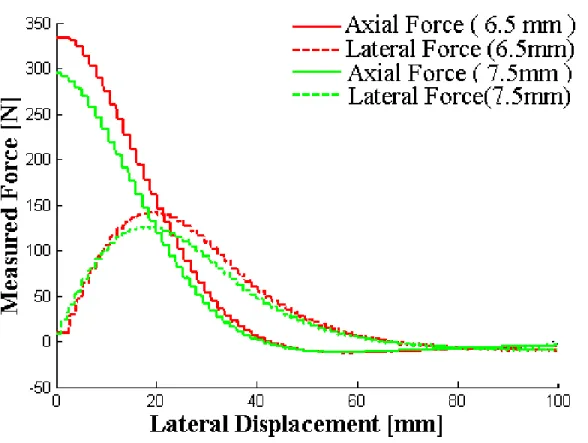
Figure 14: Axial force and lateral force one coaxial magnet pair with axial gaps x of 5.5 and 6.5 mm ... 31
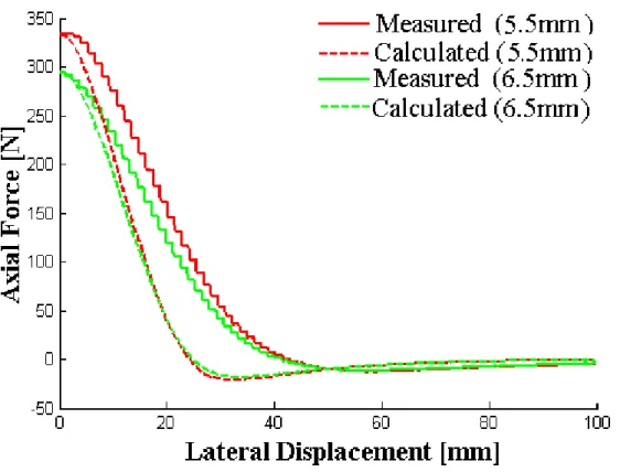
xiv Figure 15: Calculated vs measured axial force for one pair of magnets with axial gaps x of 5.5
and 6.5 mm ... 32
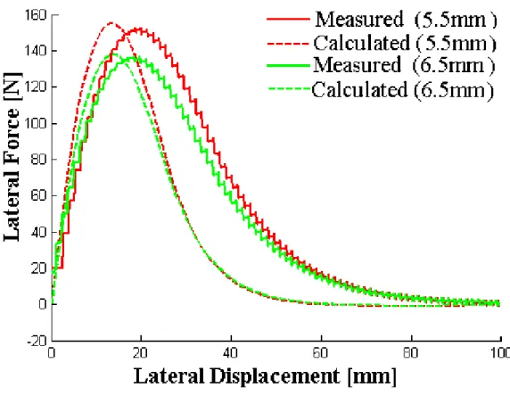
Figure 16: Calculated vs measured lateral force for one pair of magnets with axial gaps x of 5.5 and 6.5 mm ... 33
Figure 17: Axial force and lateral force with respect to lateral displacement in Y axis direction between magnet array at 5.5 and 6.5 mm axial gaps, x ... 34
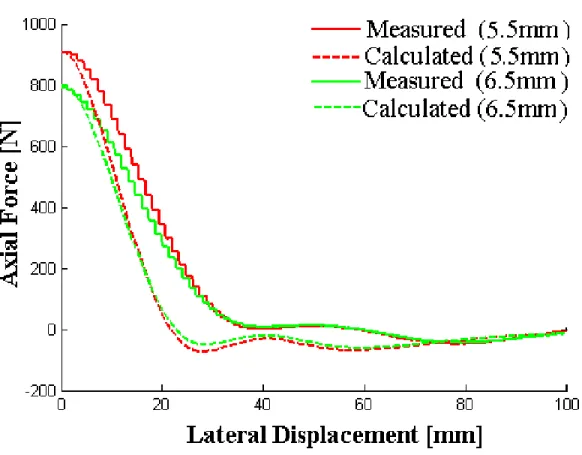
Figure 18: Calculated vs measured axial force with respect to lateral displacement in Y axis direction between magnet array at 5.5 and 6.5 mm axial gaps, x ... 35
Figure 19: Calculated vs measured lateral force with respect to lateral displacement in Y axis direction between magnet array at 5.5 and 6.5 axial gaps, x ... 36
Figure 20: Axial force and lateral force with respect to lateral displacement in X axis direction between magnet array at 5.5 and 6.5 axial gaps, x ... 37
Figure 21: Calculated vs measured axial force with respect to lateral displacement in X-axis direction between magnet array at 5.5 and 6.5 axial gaps x ... 38
Figure 22: Calculated vs measured lateral force with respect to lateral displacement in X-axis direction between magnet array at 5.5 and 6.5 axial gaps x ... 39
Figure 23: First machine for machining large and complicated shape panel (Martinez 1992) ... 44
Figure 24: Hamann (2007) device for machining aircraft panel (Hamann 2007) ... 45
Figure 25: Mirror milling systems for machining of panels. (Panczuk and Foissac 2010) ... 46
Figure 26: Conceptual design of the grasping and machining end effector. ... 47
Figure 27: Feedback control loop. ... 48
Figure 28: CATIA V5 model for the end effector ... 49
Figure 29: Double gimbal mechanism internal setup ... 50
Figure 30: Typical magnet to magnet pull (K&J magnetics 2014) ... 52
Figure 32: Bubbler type transducer ensures liquid in place by continuous supply (Olympus 2014)
... 54
Figure 33: Spring supported bubbler transducer assembly pushes against the panel surface. ... 54
Figure 34: Complete end effector assembly. ... 57
Figure 35: Stepper motor control box ... 58
Figure 36: Lab View program flow chart for depth of cut (DOC) control. ... 59
Figure 37: Experimental setup viewed from the master side ... 60
Figure 38: Experimental setup from slave side ... 61
Figure 39: Interrupted feedback caused uneven remaining thickness. ... 62
Figure 40: Random floor thickness in close loop pocket milling showing high thickness variation. ... 63
Figure 41: Open loop milling results in smoother surface finish. ... 64
Figure 42: Random floor thickness in open loop pocket milling showing lower thickness variation. ... 65
Figure 43: Concept of a grasping end effector fixed on KUKA 500 KR-2 MT industrial robot for double curved skin panel pocket milling... 66
Figure 44: Average chip thickness 𝒆𝒎𝒐𝒚(𝜽) and axial engagement 𝒅𝒂 ... 72
Figure 45: Axial engagement 𝒅𝒂 for constant depth of cut 𝒑 ... 73
Figure 46: Kistler dynamometer fixed on the CNC machine bed (model-HURON KX8) ... 76
Figure 47: LabView based data acquisition system with Kistler Dynamometer ... 77
Figure 48: Measured forces 𝑭𝒙, 𝑭𝒚 and 𝑭𝒛 in fixed workpiece reference frame ... 78
Figure 49: Fixed workpiece reference system to local reference system force components conversion ... 79
Figure 50: Experimental force data (A: fixed workpiece reference) calculated force data (B: local reference system) at 𝜶 = 𝟎 𝐝𝐞𝐠 ... 80
xvi Figure 51: A: axial engagement, 𝒅𝒂 B: average chip thickness, 𝒆𝒎𝒐𝒚 at different tilting angle
(𝜶 = 𝟎, 𝟓, 𝟏𝟎, 𝟏𝟓 𝐝𝐞𝐠 )... 81
Figure 52: Simulated verses measured cutting forces with no tilting angle (𝜶 = 𝟎 𝐝𝐞𝐠) in fixed framework ... 82
Figure 53: Thrust force at 5 degree tilting angle (𝜶 = 𝟓 𝐝𝐞𝐠)... 83
Figure 54: Thrust force at 10 degree tilting angle (𝜶 = 𝟏𝟎 𝐝𝐞𝐠) ... 84
Figure 55: Thrust force at 15 degree titling angle (𝜶 = 𝟏𝟓 𝐝𝐞𝐠) ... 85
Figure 56: 0 to 90 degree tilt angle and corresponding thrust force ... 86
Figure 57: General schematic diagram of the grasping machining end effector concept ... 90
Figure 58: Master with three extended leg (left). Slave with three sets of permanent magnets (right) (Chouinard 2011) ... 90
Figure 59: Master-slave magnetic forces in a simplified 2D view ... 92
Figure 60: Free body diagram for panel-master-slave ... 93
Figure 61: Modified free body diagram for master and slave ... 94
Figure 62: Master-slave equivalent mechanical system without the panel and associated friction and milling force ... 94
Figure 63: Lateral stiffness measurement by manual lateral force measurement with spring balance ... 97
Figure 64: Test setup for system parameter identification ... 98
Figure 65: Displacement graph for a 5 mm gap between the master and slave ... 99
Figure 66: A 5 mm gap between the master and slave is maintained by a string arrangement ... 100
Figure 67: Stiffness reduces as the master-slave gap increases (thicker plate) ... 102
Figure 68: Plate between master and slave placed where accelerometer is positioned on the slave ... 103
Figure 69: Slave displacement result for the impact hammer test of Figure 68 ... 104
Figure 71: Simultaneous acceleration data acquisition for both master and slave ... 106 Figure 72: Comparison of transfer function based simulated motion to the actual slave motion
(master slave gap 5.04 mm) ... 107 Figure 73: Comparison of transfer function based simulated motion to the actual slave motion
xviii
LIST OF SYMBOLS AND ABBREVIATIONS CNC Computer Numerical Control
HP Horse Power T Torque DOC Depth of Cut
Al-Li Aluminum lithium Alloy MMS Mirror Milling System 𝑓𝑡 Feed per tooth
𝐾𝑡(𝜃). Cutting force coefficient 𝐾𝑟 Radial to tangential force ratio 𝐾𝑎 Axial to tangential force ratio 𝑑𝑎 Axial engagement
𝑒𝑚𝑜𝑦(𝜃) Average chip thickness 𝐹𝑟 Radial magnetic force 𝐾𝑟 Magnetic lateral stiffness
𝐶𝑒𝑞 Equivalent viscous damping coefficient 𝛿 Logarithmic decrement
𝜔𝑑 Damped natural frequency 𝜔𝑛 Undamped natural frequency 𝐾𝑑 Magnetostatic energy constant
𝐽0 Bessel function of first kind of order 0 𝐽1 Bessel function of first kind of order 1 𝑥 Axial gap
CHAPTER 1 INTRODUCTION
Aircraft weight and manufacturing cost are two important concerns for aircraft manufacturers. Less weight means less fuel consumption which drives the aircraft technologist to be more directed towards weight reducing innovation. Nowadays, like all other product manufacturing, aircraft manufactures are considering the air transport impact on the environment. An aircraft starts to impact the environment from its manufacturing to its ultimate decommissioning while fuel consumption continues during the whole life cycle.
To construct a more environmentally friendly aircraft, manufacturers are putting more effort into research and development to increase fuel efficiency and are now setting new programs to achieve their high vision of fuel efficiency. Bombardier, one of the biggest North American aircraft manufacturer, announced substantial reductions in fuel consumption of around 20% in 2009 (Scott, Boehm et al. 2009). The production of the aircraft is also considered for the use of cleaner processes. Chemical milling impacts the environment by releasing waste to the environment. The replacement of the existing chemical milling with mechanical milling is getting more focused in this regard.
In some recent invention it has been shown that mechanical milling can successfully replace current chemical milling. Advanced Green Panels(Langdon 1996) project which has been completed by European Union and Airbus is the latest advancement towards mechanical milling. This system uses two independent five axis machines on opposite sides of the same skin panel moving in a coordinated manner.
The main aim of the grasping and machining end effector development research is to design a system that will do the same task with one single machine with a simple passive support system. The research will try to answer the research questions associated with the project of developing a grasping and machining end effector. The first research question “whether it is possible to mill such precision tolerance by magnetic clamping?” has been investigated by few machining operation inside the CNC machine in a laboratory setup.
The second question “how much force needs to be supported by the magnetic clamp so that the milling operation can be done without workpiece (skin panel) displacement or vibration?” It has been assumed that the clamping force much withstand the milling thrust force (force perpendicular to the skin panel coming from machining operation). So the minimum
2 clamping force should be at least the maximum milling thrust force. A torus cutter has been taken into consideration with different tilting angle and corresponding milling thrust force has been simulated to determine the maximum force. This maximum force has been declared as the minimum clamping force.
The third question is “how the slave module design could be optimized so that slave can follow the master smoothly without stick slip motion?” a master to slave motion transfer function has been established which focuses on magnetic stiffness damping constant and mass requirement of the slave design.
The fourth question aroused while answering the first question. The first question focuses on what is the required force for grasping and machining end effector. The fourth question “what axial and lateral forces are generated by a particular assembly pattern of magnets?” The slave module needs to support the milling thrust force so axial force play the vital role. But the slave module also has to overcome the friction force to remain close to the center point of the master, so the lateral magnetic force is also very important.
CHAPTER 2 LITERATURE REVIEW
2.1 Skin panel milling
Machining of shallow pockets in thin panel is a relatively new field of study. Mechanical milling method that can replace the chemical milling has already been developed by the European Aerospace Industry. Three distinctive ways of thin panel mechanical milling have been invented over the last two decades. The invented processes have a few drawbacks.
2.1.1 First machine by Martinez
In the aerospace and shipping industries, large parts are difficult to handle and fasten during the machining process. A machine was patented to support and machine these type of parts by Martinez (Martinez 1992).
The machine is a bridge type which moves along a track. The workpiece support includes multiple modules which transversely align and move independently along the tracks. All of the modules are equipped with multiple columns which can move vertically to fix the workpieces at their upper end. A computer ensures the necessary movement in all three perpendicular directions to allow the automatic positioning of the fixing members. Fixing members are manipulated to place them at the perfect positions for supporting and gripping the workpieces.
Figure 1: First machine for machining large and complicated shape panel (Martinez 1992) The machine can adapt to a variety of panel shapes without any specific template requirement and a multi-axis machining head allows machining of double curvature panels. A large number of motion controlling motors for frame, modules and even for each column which
4 needs to be independently controlled makes the system complicated to operate. Due to this vertical machining process chip evacuation is also a concern. The machine was not highly precise due to panel deflection between two neighboring columns. The thin aluminum panel is not rigid enough to counter the machining force.
2.1.2 Second solution by Hamann
Hamann patented one specialized process and device for machining large thin panels (Hamann 2007). The machine ensures isostatic positioning to one of the surfaces of a panel avoiding hyperstatism. Two registration holes located on the panel periphery at two opposite side and three reference contact points on the panel secures the isostatic positioning. At least two positioning stops, multiple mobile and prehensile suction cup and suction cup locking system holds the complex shape panel without introducing fastening stresses. Suction cups are uniformly distributed where stops are spaced less than 150 mm.
In addition to this positioning system there is a mean for measuring the actual shape of the surface of the panel. Each of the suction cups has sensors which measure the distance of panel surface from base. Sensor signals are interpolated to calculate the shape of the panel surface. A milling trajectory is calculated considering the interpolated surface as a reference plane. A multi-axis machining head follows the trajectory keeping perpendicular to the machining window. Every machining window needs to adjust the holding stops and suction cups at successive displacement and location.
Figure 2: Hamann (2007) device for machining aircraft panel
Figure 2 shows the structure of the machine (Hamann 2007). “Panel 1 is machined on the geometrically known surface 1a which is the concave internal surface and 1b is the reference surface. The multi-axis machining head 6 is under the panel 1. Means 7 supports and position the panel carried by the gantry 5. Means 8 holds upper convex surface 1b of the panel 1. The panel 1 is supported perpendicular by the three horizontal beams assembly 11. Assembly 11 is attached to the two swing bars 12. Beams and swings bars are perpendicular. Swings bars end are held by clamps 13. The clamps 13 are in turn taken up by arms 14. Arms 14 can slide along vertical axis on cross piece 15 with the help of sliding coupling 16. The head 21 can be moved manipulator 22. Suction cup 20 installed on head 21. The machining head 6 can slides on guides 26 and can also swivel by the ball and socket joint 28 located between head 6 and support feet 29.”
The process calculates the machining trajectory referencing to the external surface (opposite side of machining surface). The stretching or drawing processing does not generate a uniform thickness on the whole surface of the panel. This device takes into account the instantaneous shape variation, where thickness variation is also needed to consider for a precise control of depth precision.
Hamann mentions a precision accuracy of less than 0.2 mm whereas the current project aims to attain a tolerance of ±0.050 mm. This machine is bulky with at least 50 different machine components and complex controls for positioning, fitting of window and trajectory correction.
6 2.1.3 Panczuk-Foissac mirror milling system
The latest solutions developed for thin aircraft panel machining of co-ordinated motion. These solutions are more known as Mirror Milling Systems (MMS). Hamann (Hamann, 2009) and Panczuk-Foissac (Panczuk and Foissac, 2010) both solved the problem on behalf of Airbus France.
In Hamann solution (Hamann 2009), a tool is applied on the first surface of the panel and the numerically controlled machine positions this tool. The machining force exerted to the thin panel is counter-balanced by a multi-axial mobile support which is usually a metallic sphere. The mobile support moves along thee Cartesian axes as well as rotates along two rotational axes to mirror the machining head.
Figure 3: Mirror milling systems for machining of panels. (Panczuk and Foissac 2010) Figure 3 describes the main feature of the mirror milling system (Panczuk and Foissac 2010). “The machining operation is favoured by the kinetics of the end of arms 25 and 26 and of the support 26 around axes R1 , R2 and R’1 and R’2. The tool bearing head 27fits on to the head support 26 which is moved by a telescopic arm 25. On the other side head support 36 is mounted on the telescopic arm 35. A retention-element-carrying head 37 is connected to retention element 13. The body 42 has a tapered shape containing sphere 41 at the end 40. Panel 2 has a retention face 2M and machining face 2T. Working area is 50 where 52 is retention area. Tool bearing head 27 has the tool 11 doing the machining job.”
In Panczuk-Foissac solution (Panczuk and Foissac 2010), one machining tool on the machining face and one retention element on the retention face each are having at least five axes of motion to follow a coordinated movement. The panel is oriented more or less vertical allowing gravitational chip removal.
Scanning is performed by an optical sensor mounted on the machining head to determine the actual shape and form of the panel. This allows the machine to work with a wide range of panel forms where the real and nominal forms are different caused by uneven loss of thickness during the drawing process.
However, these solutions and the machines involved are very expensive since in both cases large and complex machines are necessary. Both sides require a multi axis mechanical system and a complex synchronization of the motion of the systems on opposite sides.
2.2 Minimum clamping force determination
While designing the end effector the first consideration was how much force should be supported against the skin panel by the clamp. Finite-element (FE) modeling approach is very common in clamping force optimization. Due to large model size and greater computational cost they are not efficient. Genetic algorithm based fixture layout and clamping force optimization method (Liu, Wang et al. 2012) was proposed with a reduced matrix size for FEM balance equation.
Both rigid body and elastic contacts method has been developed for clamping force optimization. Considering the workpiece and the fixture as perfectly rigid body Wang et al. (Wang and Pelinescu 2003) solved clamping force optimization model. Representing the fixture-workpiece contact as elastic contacts, Li et al (Li and Melkote 2001) estimated optimum clamping force in the case of multiple clamp fixture.
Contact forces for known clamping forces have been predicted by Xiong et al. (Xiongand, Xiong et al. 2003) using nonlinear programming. Wang and Pelinescu et al. (Wang and Pelinescu 2003) used constrained quadratic optimization programming. Computational intelligence Particle Swarm Optimization (PSO) techniques featuring computational intelligence has been used for clamping force optimization by Deng and Melkote (Deng and Melkote 2006). Balancing force-moment method and the coulomb static friction law were used to determine
8 minimum clamping force to hold the workpiece without deformation by S. Selvakumar et al. (Selvakumar, Arulshri et al. 2010)
The prime drawbacks of these aforementioned methods are that they are developed assuming that the workpiece and clamp contact is static. The magnetic grasping and machining end effector is different, here the clamp slides over the workpiece (skin panel).
2.3 Lateral sliding motion modeling
The slave module follows the master module motion by lateral sliding motion. Lateral sliding occurs due to lateral magnetic forces between two sets of magnetic unit such as magnetic couplings. In case of magnetic coupling torque is transmitted from inner rotor to outer rotor without any radial displacement. P. Elies (Elies and Lemarquand 1999) analyzed this radial stability characteristics in transmitting torque through air gap.
In a permanent magnet bearing there are two different magnetic attraction forces, axial and radial. J.P. Yonnet (Yonnet 1981) defined lateral magnetic stiffness while discussing radial magnetic properties in magnetic bearing and couplings. D. Vokoun et al. (Vokoun, Beleggia et al. 2009) calculated the attraction force between two cylindrical permanent magnets with a common axis. The calculation also estimated the axial attraction force when there is a lateral gap between the couple magnets. This static model is not able to predict whether the slave module is lagging behind by stick-slip motion or perfectly following the master.
Lateral sliding motion has been modeled based on a motion transfer function from master to slave using the concept of magnetic stiffness as defined by J.P. Yonnet (Yonnet 1981). His transfer function has been evaluated against real experimental results obtained from inside laboratory test.
2.4 Lateral magnetic force modeling
According to the proposed design of the grasping and machining end effector, there are three closely located pairs of cylindrical magnets providing the support force to keep the panel in position and the drag force to the slave module for sliding. Support force results from axial magnetic attraction force and drag forces comes from lateral magnetic attraction force.
Fictitious magnetization charges and the discretization technique were used by Vučković et al. (Vučković, Ilić et al. 2013) whom developed a semi-analytical approach to estimate magnetic levitation force between two laterally displaced cylindrical permanent magnet.
Mutual inductance (axial force) between two axially magnetized cylindrical magnet has been studied and expressed analytically by Ravaud et al. (Ravaud, Lemarquand et al. 2010). Robertson et al. (Robertson, Cazzolato et al. 2011) proposed a simplified expression which reduce computational time.
Agashe and Arnold (Agashe and Arnold 2008) exploited Kelvin formula to analyze the attraction forces between two uniformly magnetized cylindrical magnet. Vokoun et al. (Vokoun, Beleggia et al. 2009) used a Bessel function based attraction force equation to elaborate axial force for more than two cylindrical magnets with the special case of two groups magnet set each comprising four magnets. Later Vokoun et al. (Vokoun, Tomassetti et al. 2011) generalized the attraction force equation for two infinite arrays of cylindrical magnet.
Frictional forces hinder the slave motion to perfectly follow the master motion which results in a lateral displacement between the master and slave module. Vokoun’s Bessel function based equations are satisfactory to explain the axial magnetic forces while a lateral gap is introduced. But lateral magnetic forces which impart the drag force yet need to be modeled.
10 CHAPTER 3 OBJECTIVES
3.1 Problem formulation
Aircraft weight reduction is an important issue for aerospace industry. So the aluminum or Al-Li skin panels need to be as thin as possible. Currently, the thinning tasks are accomplished by creating pockets in the skin panel by chemical machining. Unfortunately, this chemical machining process ends with chemical pollutants to the environment. Most of the chemicals such as cleaning solutions, etchants, strippers etc. are very hazardous liquids. Specially, etchants are very dangerous for workers (Cakir, Yardimeden et al. 2007). With the growth of the aerospace industry this issue of health, safety and environmental pollution is getting more and more attention since a decade or so. So, replacing this industrial chemical milling process with a lower emission and more environment friendly process is sought. Mechanical milling is promising in this case because this process finishes with recyclable metal chips and eliminates the requirement for costly etchant disposal and metal recovery from waste etchants.
Chemical milling also uses more electricity compared to mechanical milling and produces much carbon dioxide whereas mechanical milling is carbon dioxide free (Langdon 1996).Due to the previous stage of stretching most of the panel gets high variation of initial thickness. Chemical machining process has a constant material removal rate (MRR). Since the panel has initial thickness variation and a constant thickness is removed, the remaining pocket floor thickness is irregular and imprecise. Applying mechanical milling is also critical due to the initial thickness variation because a single depth of cut cannot assure a fixed remaining thickness of the panel.
Chemical milling process is not capable of attaining different depth of cut in a single operation. One single operation provides one specific depth of cut depending on the exposure time to an etchant. So there is a long process cycle of aircraft thinning operation composed of several steps for different depth of cut.
One of the characteristic of aircraft panels is double curvature. Though five axis CNC milling or six degree freedom robotic milling can easily machine a double curvature plane, here the scenario is complicated due to thinness. Low stiffness of thin panel creates problem by unpredictable deformation during cutting operation. The greatest challenge is to maintain high precision in the pocket floor remaining thickness.
3.1.1 Research questions
How can the remaining panel thickness be maintained according to the specified level of accuracy while maintaining higher cutting efficiency?
It is possible to machine a double curvature skin panel with a grasping and machining end effector?
How much clamping force must be supported by the grasping and machining end effector for a milling operation?
How can the slave module design be optimized so that the slave can follow the master smoothly without stick slip motion?
Can a model be established between the magnet properties and the required axial and lateral forces between the master and slave modules?
3.1.2 General objectives
Develop an automated mechanical milling system assisted by an industrial manipulator that is able to mill pockets in a thin Al-Li skin of double curvature form.
3.1.3 Specific objectives
Develop a grasping mechanism that will hold the thin skin panel to counteract milling force and integratable to a manipulator;
Develop a simplified passive mechanism to allow the milling spindle tilting relative to the skin panel leading to higher cutting efficiency;
Integrate a feedback control loop with sensors to ensure the precise tolerance (±0.002 inch / ±0.050 mm) of the cut.
Model the lateral sliding motion of a magnetic clamp. 3.1.4 Hypothesis
A grasping and machining end effector will be implemented to accomplish the purpose of mechanical milling of pockets in aluminum or Al-Li skin panel. A well-equipped clamping technique can restrict the thin skin deformation and make it more resistant to lateral friction forces. The end effector will start material removal by a milling cutter. Sensory feedback of the
12 remaining thickness will ensure the high precision tolerance allowance. The robotic manipulator will move on the skin surface according the pre-specified pocket dimension and the self-feed spindle motion of the milling cutter will provide depth of the cut for making shallow pockets in the skin panel.
3.1.5 Design specification
The design must use magnetic forces as a medium of grasping mechanism following the earlier version developed by Abel Chouinard (Chouinard 2011).
The end effector must be able to mill thin (0.063 inch to 0.250 inch) skin panel which is highly flexible.
The end effector must be able to maintain the same floor bed thickness all-over the pocket in spite of the initial thickness variation of 5 % from the stretching process.
The end effector must be able to follow the double curvature for milling operation where the minimum radius of curvature is 24 inch and maximum 70 inch.
The work envelope (work area) of the end effector must be big enough to mill large skin panel of which typical dimension is 2 ft. x 3ft. to 9 ft. x 19 ft.
The minimum remaining skin panel floor bed thickness can be as small as 0.016 inch with a tolerance limit of +/- 0.002 inch.
The end effector design should provide higher productivity with respect to material removal rate in machining pockets (dimensions - width (2 inch to 6 inch tolerance +/- 0.060 inch x L (2 inch to 24 inch tolerance +/- 0.060 inch) x depth (0.200 inch)).
The total weight of the end effector should not exceed the weight tolerance level of the commercial robot manipulator to maintain accuracy.
The design should consider the work environment condition (dust, debris, chips cutting fluid etc.) while selecting the building components.
The design should include as much non-magnetic material as possible to reduce interaction with magnets in the grasping mechanism.
Considering the prototype development is just an academic test procedure rather than an industrial application the cost of the components needs to be optimized.
3.1.6 Organization of the articles
The first article in Chapter 4 is entitled “Magnetic attraction forces between permanent magnet groups in magnetic clamp for pocket machining”. This paper answers the research question “What types of magnetic properties need to be investigated for the magnet selection in case of designing a magnetic clamp?” The paper states that axial magnetic force provides the required support for milling operation against the milling thrust force. Since drag force is required to surpass the slave to skin panel friction forces, the paper analyze the lateral magnetic force among the magnets of a pair in a group. This paper describes an analytical force measurement between two permanent magnet groups arranged in triangular array fashion to verify if the forces are sufficient to support against milling forces and frictional forces for a mobile magnetic clamp. This article has been submitted to the CIRP Journal of Manufacturing Science and Technology on 27th April 2015
The second article, presented in Chapter 5 is entitled “Mechanical pocket milling of thin aluminum panel with a grasping and machining end effector”. This work proposes a process for thin skin plate milling with a magnetic grasping end effector. The three main impediments to mechanical milling is skin panel’s thinness causing low stiffness, double curvature and tight pocket floor thickness tolerance. The novel idea of a magnetic grasping end effector theoretically overcomes these problems. An end effector prototype has been assembled and a few tests have been completed inside a CNC machine with satisfactory results establishing a base for future development. The research question is how the remaining panel thickness could be maintained according to the specified level of accuracy while maintaining higher cutting efficiency? To answer this question a dynamic depth of cut strategy which works with continuous feedback of instantaneous thickness based milling system has been proposed. The proposal has been evaluated by developing a prototype end effector and completing laboratory tests. Another research question “It is possible machining a double curvature skin panel with grasping and machining end effector?” has been addressed by the double gimbal mechanism. It is a passive mechanism which adopts the inclination of the panel curvature without any prior guidance. The double gimbal mechanism also helps for higher cutting efficiency. This article has been submitted to the Journal of Cleaner Production on 26th January 2015.
The third article, presented in Chapter 6, is entitled “Determining the minimum clamping force by cutting force simulation in aerospace fuselage pocket machining”. This article mainly answers the research question “How much clamping force must be provided by the grasping and
14 machining end effector for milling operation?” The paper helps to determine the required minimum clamping force for designing a grasping and machining end effector. In this work, a specific model for torus cutter milling force and a general milling force model have been simulated to predict the cutting forces. In order to get higher cutting efficiency the torus cutter need to adopt different tilt angle relative to the workpiece which changes the thrust force. An equation has been developed to predict the resulting thrust force on the skin panel at different tilting angle. Simulated thrust force results have been validated against dynamometer readings acquired during milling operation. This article has been published in the Journal of Advanced manufacturing Technology on 29 Apr 2015, Digital Object Identifier (DOI) -10.1007/s00170-015-7104-4 http://link.springer.com/article/10.1007/s00170--10.1007/s00170-015-7104-4.
The article in Chapter 7 is entitled “Modeling of laterally sliding motion of a magnetic clamp”. This paper mainly targets the research question “How the slave module design could be optimized so that slave can follow the master smoothly without stick slip motion?” This paper proposes a model for the lateral sliding motion of the master to slave module by magnetic attraction forces. The lateral sliding motion of the slave module in response to the master module motion is studied using a transfer function based motion model established considering the lateral magnetic stiffness. The transfer function shows that the slave mass and lateral magnetic stiffness play vital roles in the slave response motion resulting from the imparted master’s motion. Friction coefficient of the pad material with respect to the skin material has been taken into consideration while developing the transfer function. The transfer function shows that slave mass, friction coefficient and lateral magnetic stiffness could be analyzed to ensure a smooth slave motion avoiding stick-slip. This article has been submitted to the Journal of Vibration and Control on 12th April 2015.
CHAPTER 4 ARTICLE 1: MAGNETIC ATTRACTION FORCES BETWEEN PERMANENT MAGNET GROUP ARRAYS IN A MOBILE MAGNETIC CLAMP FOR POCKET MACHINING
A. Mahmud, J.R.R Mayer, L. Baron (2015)
Submitted to CIRP Journal of Manufacturing Science and Technology
Abstract—A mobile magnetic clamp was recently tested for pocket milling on a fuselage panel. The magnetic clamps need to provide sufficient support force against the milling thrust force and sufficient drag force to overcome the frictional force. Triangular arrays of cylindrical permanent magnets are used. Axial magnetic attraction forces between magnet groups are calculated based on recently published formula at various axial heights and lateral displacements. A model is here proposed to estimate lateral magnetic attraction forces as a function of lateral displacement between two cylindrical permanent magnets. Experiments conducted using a dynamometer table to validate the measured axial and lateral magnetic forces strongly support the analytically predicted magnetic forces.
Index Terms — Magnet array, cylindrical permanent magnet, magnetic axial force, Lateral magnetic force, Pocket machining
4.1 Introduction
This paper describes an analytical force model between two permanent magnet groups arranged in a triangular array fashion. The model is then used to assess whether the forces generated are sufficient to counteract both the milling forces and frictional forces affecting the mobile magnetic clamp. The magnetic clamp (Chouinard 2011) main function is to hold a panel while pockets are machined on its surface. At the same time since it must slide over the panel, friction forces are generated. Axial magnetic attraction force between three closely located pairs of cylindrical magnets provides the support force to keep the panel in position. Lateral attraction force between the cylindrical permanent magnet pulls the slave part of the clamp over the panel to keep it close to the master part of the clamp. Axial and lateral magnetic force directions are shown in Figure 4.
16
Figure 4: Axial and lateral magnetic force direction in the mobile magnetic clamp
Vučković et al. (Vučković, Ilić et al. 2013) presented a semi-analytical approach for the determination of the magnetic levitation force between two laterally displaced cylindrical permanent magnets. Fictitious magnetization charges and the discretization technique were adopted for cylindrical magnets assuming similar magnetic material and uniform magnetization along their axes of symmetry (opposite direction).
Ravaud et al. (Ravaud, Lemarquand et al. 2010) published an analytical expression to calculate the mutual inductance (axial force) between two axially magnetized cylindrical permanent magnets in air. Due to high computation time and complex valued results a simplified equation was later proposed by Robertson et al. (Robertson, Cazzolato et al. 2011).
Formulas have also been proposed by Agashe and Arnold (Agashe and Arnold 2008) for the attraction forces between two uniformly magnetized cylindrical permanent magnets. Kelvin formula was employed to derive explicit analytical solutions for axial and lateral forces. Long and elaborated equations result for practical application based calculation.
All aforementioned paper considered face to face (aligned with no lateral displacement) interaction of a single pair of permanent cylindrical magnet but Vokoun et al.(Vokoun, Beleggia et al. 2009) used a Bessel function based attraction force equation to elaborate axial force for more than two cylindrical magnets with the special case of two groups magnet set each comprising four magnets. Later Vokoun (Vokoun, Tomassetti et al. 2011) generalized the attraction force equation for two infinite arrays of cylindrical magnet.
In the case of a mobile magnetic clamp the corresponding magnets of each group do not remain coaxial. Due to frictional forces the slave module lags behind the master module introducing a lateral displacement. It is necessary to estimate the axial force between master and slave triangular magnets groups considering this lateral displacement. In this paper Vokoun’s Bessel function based equation are used for determining the axial magnetic force between triangular magnetic groups for different lateral and axial displacement. Additionally, a formulation is proposed, and experimentally validated, to explain the lateral magnetic force using Bessel function of the first kind.
4.2 Theoretical framework
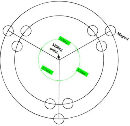
The mobile magnetic clamp has three gripping sets forming, with the contact mechanisms, a kinematic contact system to avoid redundancy and contact ambiguity in planar gripping. Three permanent cylindrical magnets are used at each group to support the axial force generated by the milling operation. Each group has three magnets at the vertices of an equilateral triangle. These three groups of permanent magnets are located on a circumference 120 degrees apart completing the array (Figure 5). Similar arrangements are adopted both in the master and slave array. A magnet in the master module array has an opposite magnet in the slave module array, forming a pair. The magnets of each pair are nominally coaxial.
18
Figure 5: Three magnet group (each group comprised of three individual magnets) located in the master array and slave array
Figure 6: Ball transfer unit are placed at the centroid of the equilateral triangle with magnets at its vertices
The clamping contact point is at the centroid of each group where a ball transfer unit is attached (Figure 6). A magnet attracts the opposite pole and repels the similar pole. Since these permanent magnets are axially magnetized the N-S-N-S orientation is used to get the highest possible attraction force as shown in Figure 7
20
Figure 7: A magnet group (M1, M2 and M3) in the master array coaxial to another magnet group (S1, S2 and S3) in the slave array in static (nominal) condition
Coaxial magnets located in the master and slave array have their own magnetic attraction forces between them (Figure 7). However, the other two magnets of the same group have an influence on that force as they are closely located. This was accounted for with the introduction of a force ratio representing the array contact force enhancement by Vokoun et al (Vokoun and Beleggia 2014). Furthermore, the member magnets of the other groups present in the array have influence on each other. However, as will be shown in the results section, such effects are negligible, due to the significant distance between the groups, and so will be ignored in the calculation. Only the influence of the magnets of the same group will be considered.
Vokoun et al. (Vokoun, Beleggia et al. 2009) expressed the axial attraction force Fz for two coaxial cylindrical permanent magnet of magnetization 𝑀, radius 𝑅, thickness 𝑡, axial gap 𝑥 and lateral displacement 𝑟 in equation 4.1 using aspect ratio 𝜏𝑖 = 𝑡𝑖/(2𝑅), 𝑖 = 1, 2, and 𝜁 = (𝑡1 + 𝑡2)/(2𝑅) + 𝑥/𝑅.
𝐹z= −8 π𝐾𝑑𝑅2 ∫ 𝐽 0( 𝑟𝑞 𝑅) 𝐽12(𝑞) 𝑞 sinh(𝑞𝜏1) sinh(𝑞𝜏2) 𝑒−𝑞𝜁𝑑𝑞 +∞ 0 (4.1)
where the magnetostatic energy constant 𝐾𝑑 = 𝜇0𝑀2/2.
In case of a group magnet instead of a magnet pair this Bessel function based equation was modified to include multiple magnets influence to the base pair attraction force. Vokoun (Vokoun, Beleggia et al. 2009) modified the equation with indexation 1, 2, …, n ( first group) to n+1, n+2, ..., m (second group). 𝐹𝑧 = −8 𝜋𝐾𝑑𝑅2∑ ∑ ∫ 𝐽0( 𝑟𝑖𝑗𝑞 𝑅 ) 𝐽12(𝑞) 𝑞 sinh(𝑞𝜏1) sinh(𝑞𝜏2) 𝑒−𝑞𝜁𝑑𝑞 +∞ 0 𝑚 𝑗=𝑛+1 𝑛 𝑖=1 (4.2)
In the mobile magnetic clamp each magnet group forms an equilateral triangle of side length 𝐿. So the magnet axis to axis distance is equal to 𝐿. Therefore equation 4.2 can be rewritten in term of lateral displacements 𝐿.
𝐹𝑧 = −24 𝜋𝐾𝑑𝑅2 ∫ [1 + 2𝐽 0( 𝐿𝑞 𝑅)] 𝐽12(𝑞) 𝑞 sinh(𝑞𝜏)2𝑒−𝑞𝜁𝑑𝑞 +∞ 0 (4.3) with 𝜏 = 𝑡/2𝑅, 𝑡 = 𝑡1 = 𝑡2 and 𝜁 = (𝑡 + 𝑥)/𝑅.
During milling the master magnet array pulls the slave magnet array by the lateral magnetic force. Friction force hinders the slave magnet array to be coaxial with the master magnet array introducing a lateral displacement. The lateral displacement 𝐿 between magnets of opposing groups may vary. For example if the master moves a distance r in the Y-axis direction the relative magnet positions are as shown in Figure 8.
22
Figure 8: A magnet group (M1, M2 and M3) in the master array moves a distance r in the Y-axis direction with respect to the nominally coaxial magnet group (S1, S2 and S3) in the slave array
Equation 4.3 can be rearranged to calculate the axial magnetic forces between a magnet group in the master array and a magnet group in the slave array.
𝐹𝑧 = −8 𝜋𝐾𝑑𝑅2 ∫ [ 𝐽0(𝑟𝑞 𝑅) +∞ 0 + 2𝐽0 ( √𝑟2+ 𝐿2− 2𝑟𝐿𝑐𝑜𝑠 (5𝑝𝑖 6 ) 𝑞 𝑅 )] 𝐽12(𝑞) 𝑞 sinh(𝑞𝜏)2𝑒−𝑞𝜁𝑑𝑞 − 16 𝜋𝐾𝑑𝑅2 ∫ [ 𝐽0( 𝑟𝑞 𝑅) + 𝐽0 ( √𝑟2+ 𝐿2− 2𝑟𝐿𝑐𝑜𝑠 (𝑝𝑖 3 ) 𝑞 𝑅 ) +∞ 0 + 𝐽0( √𝑟2+ 𝐿2𝑞 𝑅 ) ] 𝐽12(𝑞) 𝑞 sinh(𝑞𝜏)2𝑒−𝑞𝜁𝑑𝑞 (4.4)
The same distance shift but in the X direction causes a different positional geometry. The mutual internal relative distances among each magnet of a group while moving in the X direction are given in Figure 9. The corresponding magnetic axial forces between the master magnet group and the slave magnet group is expressed by Equation 4.5 .
Figure 9: A magnet group (M1, M2 and M3) in master array moves a distance r in the X-axis direction with respect to coaxial magnet group (S1, S2 and S3) in slave array
24 𝐹𝑧 = −8𝜋𝐾𝑑𝑅2 ∫ [ 𝐽0(𝑟𝑞 𝑅) + 𝐽0 ( √𝑟2 + 𝐿2− 2𝑟𝐿𝑐𝑜𝑠 (𝑝𝑖 3 ) 𝑞 𝑅 ) +∞ 0 + 𝐽0 ( √𝑟2+ 𝐿2− 2𝑟𝐿𝑐𝑜𝑠 (2𝑝𝑖 3 ) 𝑞 𝑅 )] 𝐽12(𝑞) 𝑞 sinh(𝑞𝜏)2𝑒−𝑞𝜁𝑑𝑞 − 8𝜋𝐾𝑑𝑅2 ∫ [ 𝐽0( 𝑟𝑞 𝑅) + 𝐽0 ( √𝑟2+ 𝐿2− 2𝑟𝐿𝑐𝑜𝑠 (2𝑝𝑖 3 ) 𝑞 𝑅 ) +∞ 0 + 𝐽0( (𝐿 + 𝑟)𝑞 𝑅 ) ] 𝐽12(𝑞) 𝑞 sinh(𝑞𝜏)2𝑒−𝑞𝜁𝑑𝑞 − 8𝜋𝐾𝑑𝑅2 ∫ [ 𝐽0( 𝑟𝑞 𝑅) + 𝐽0 ( √𝑟2+ 𝐿2− 2𝑟𝐿𝑐𝑜𝑠 (𝑝𝑖 3 ) 𝑞 𝑅 ) +∞ 0 + 𝐽0( (𝐿 − 𝑟)𝑞 𝑅 ) ] 𝐽12(𝑞) 𝑞 sinh(𝑞𝜏)2𝑒−𝑞𝜁𝑑𝑞 (4.5)
In the case of a cylindrical permanent magnet the radial (lateral) stiffness is half the axial stiffness (Elies and Lemarquand 1999). The same relation has also been admitted by Yonnet (Yonnet 1981). Following their equation the lateral magnetic force is expressed by Equation 4.6 if only a pure X or Y displacement occurs
𝐹𝑥 = 𝐹𝑦 = 1
2𝐹𝑧 (4.6)
Although Equation 4.6 provides a general idea of maximum lateral magnetic force as a ratio to maximum axial magnetic force, it does not specify exactly the amount of lateral force at each single point based on the lateral displacement of a magnet from the other magnet of a pair.
Lateral magnetic attraction force Fx or Fy for two coaxial cylindrical permanent magnet of magnetization 𝑀, radius 𝑅, thickness 𝑡, axial gap 𝑥 and lateral displacement 𝑟 could be modeled as Equation 4.7 using aspect ratio 𝜏𝑖 = 𝑡𝑖/(2𝑅), 𝑖 = 1, 2, and 𝜁 = (𝑡1+ 𝑡2)/(2𝑅) + 𝑥/𝑅.
𝐹𝑥 = 𝐹𝑦 = −8 π𝐾𝑑𝑅2 ∫ 𝐽 1( 𝑟𝑞 𝑅) 𝐽12(𝑞) 𝑞 sinh(𝑞𝜏1) sinh(𝑞𝜏2) 𝑒−𝑞𝜁𝑑𝑞 +∞ 0 (4.7)
where the magnetostatic energy constant 𝐾𝑑 = 𝜇0𝑀2/2.
Equation 4.7 establishes the lateral magnetic force between two coaxial magnet of a pair. This relation could be used for explain the interaction forces among the groups of a magnet array. When a magnet group in master magnet array moves in Y axis direction as described in Figure 8, the lateral magnetic force is expressed as equation 4.8.
𝐹𝑦 = −8 𝜋𝐾𝑑𝑅2 ∫ [ 𝐽1(𝑟𝑞 𝑅) +∞ 0 + 2𝐽1 ( √𝑟2+ 𝐿2 − 2𝑟𝐿𝑐𝑜𝑠 (5𝑝𝑖 6 ) 𝑞 𝑅 )] 𝐽12(𝑞) 𝑞 sinh(𝑞𝜏)2𝑒−𝑞𝜁𝑑𝑞 − 16 𝜋𝐾𝑑𝑅2 ∫ [ 𝐽1(𝑟𝑞 𝑅) + 𝐽1 ( √𝑟2+ 𝐿2− 2𝑟𝐿𝑐𝑜𝑠 (𝑝𝑖 3 ) 𝑞 𝑅 ) +∞ 0 + 𝐽1(√𝑟2 + 𝐿2𝑞 𝑅 ) ] 𝐽12(𝑞) 𝑞 sinh(𝑞𝜏)2𝑒−𝑞𝜁𝑑𝑞 (4.8)
Similarly when the magnet group in master magnet array moves in the X-axis direction relative to the other magnet group in slave array as described in Figure 9, the lateral magnetic force between these two groups is expressed as in Equation 4.9.
26 𝐹𝑥 = −8𝜋𝐾𝑑𝑅2 ∫ [ 𝐽1(𝑟𝑞 𝑅) + 𝐽1 ( √𝑟2+ 𝐿2− 2𝑟𝐿𝑐𝑜𝑠 (𝑝𝑖 3 ) 𝑞 𝑅 ) +∞ 0 + 𝐽1 ( √𝑟2+ 𝐿2− 2𝑟𝐿𝑐𝑜𝑠 (2𝑝𝑖 3 ) 𝑞 𝑅 )] 𝐽12(𝑞) 𝑞 sinh(𝑞𝜏)2𝑒−𝑞𝜁𝑑𝑞 − 8𝜋𝐾𝑑𝑅2 ∫ [ 𝐽1( 𝑟𝑞 𝑅) + 𝐽1 ( √𝑟2 + 𝐿2 − 2𝑟𝐿𝑐𝑜𝑠 (2𝑝𝑖 3 ) 𝑞 𝑅 ) +∞ 0 + 𝐽1( (𝐿 + 𝑟)𝑞 𝑅 ) ] 𝐽12(𝑞) 𝑞 sinh(𝑞𝜏)2𝑒−𝑞𝜁𝑑𝑞 − 8𝜋𝐾𝑑𝑅2 ∫ [ 𝐽1( 𝑟𝑞 𝑅) + 𝐽1 ( √𝑟2 + 𝐿2 − 2𝑟𝐿𝑐𝑜𝑠 (𝑝𝑖 3 ) 𝑞 𝑅 ) +∞ 0 + 𝐽1( (𝐿 − 𝑟)𝑞 𝑅 ) ] 𝐽12(𝑞) 𝑞 sinh(𝑞𝜏)2𝑒−𝑞𝜁𝑑𝑞 (4.9) 4.3 Experimental setup
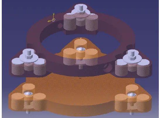
The prototype developed based on the magnetic grasping principle works with the master attached to the moving spindle and sliding over the panel while machining with the slave being pulled along magnetically on the other side of the skin panel. Figure shows the regular operation pattern of the prototype. Force measurement by a force dynamometer is difficult in such environment.
Figure 10: Master module (left of panel) and slave module (right of panel) magnet array in a magnetic grasping milling prototype setup
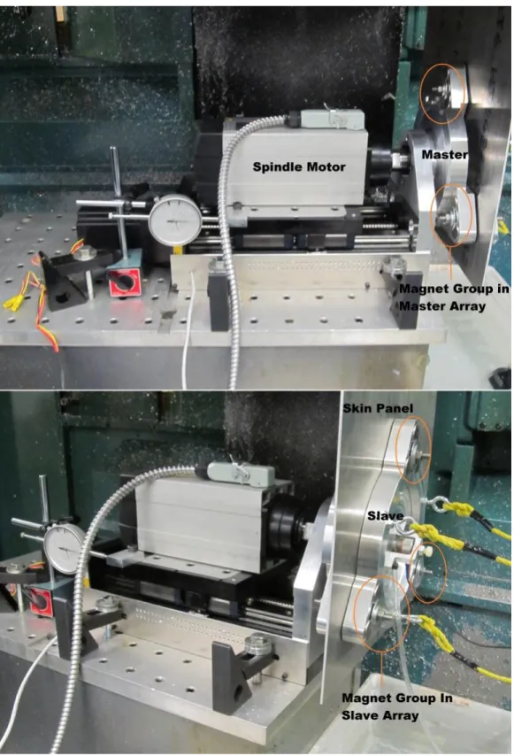
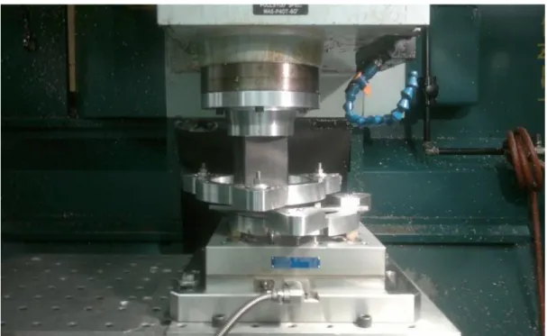
28 For the experimental setup both the master and slave modules are removed from the prototype and firmly secured inside a CNC milling machine as shown in Figure .
Figure 11: Master module attached to the CNC spindle and slave module fixed to the top of the dynamometer itself attached to the machine tool table
The master module was attached to the machine spindle with some additional fixture so the spindle does not rotate. The slave module was firmly attached to the Kistler dynamometer. For a relative displacement in the Y-axis or X-axis directions the spindle position is controlled by the CNC as shown in Figure 12 and Figure 13. The same setup also helps to change the axial gap between the master and slave magnet arrays in the Z-axis direction.
Figure 12: Master magnet array with lateral displacement along Y-axis with respect to the slave magnet array
Figure 13: Master magnet array is lateral displacement along X-axis with respect to the slave magnet array
30 two 8 channel cards PXI 4472 via the amplifier.
4.4 Results and verification
Using the basic magnet properties 1 inch diameter and 1 inch thick magnet with magnetization value of 1 MA/m) Equation 4.1 was simulated for a range of lateral distances for one single pair of cylindrical permanent magnet. From the simulated results it is observed that beyond 100 mm of lateral distance the axial forces tend to zero.
The first experiment was conducted with one single magnet in each group (removing the other two) for both the master and slave modules. The kept magnets in the master array were nominally coaxial with the magnets in the slave array. This experiment helped to verify Equation 4.1 where only a single magnet pair is considered for force estimation.
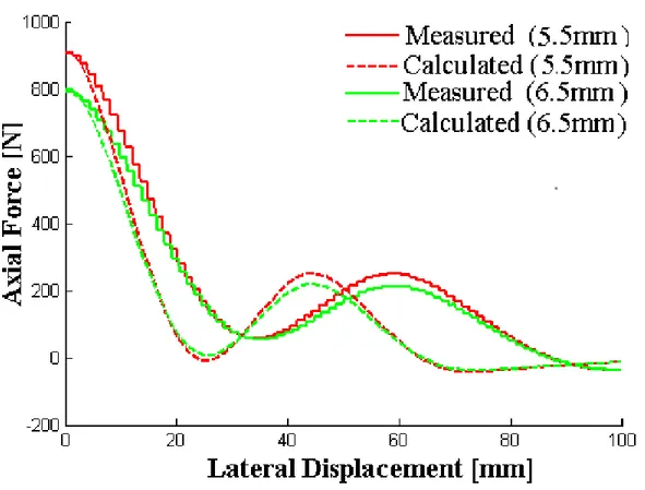
Both the axial and lateral forces between magnets of a pair of magnet are plotted in one single graph in Figure 14. It has been found that the maximum lateral forces is almost equal to half the maximum axial forces as predicted in Equation 4.6. For an axial gap of 6.5 mm between magnets of a pair the maximum lateral force is 150 N which is close to the half of axial force of 330 N.
Figure 14: Axial force and lateral force one coaxial magnet pair with axial gaps x of 5.5 and 6.5 mm
Axial forces are calculated by Equation 4.1 for a range of lateral distances which is then compared with the measured ones as shown in Figure 15. Two values of the axial gap x were used. A larger axial gap results in lower axial force. Increasing lateral displacement also results in lower axial force and the tends towards zero at large lateral displacement.
32
Figure 15: Calculated vs measured axial force for one pair of magnets with axial gaps x of 5.5 and 6.5 mm
The proposed lateral force model as described in Equation 4.7 has been tested against the experimental value obtained with one coaxial magnet pair located in master and slave array. Figure 16 show the comparison between the proposed model based calculated force and experimental measured. It is observed that the calculated force tends to increase and then fall quickly as the lateral displacement increases. Measured force follows a slow decrease compared to the calculation based on the proposed lateral force model.
Figure 16: Calculated vs measured lateral force for one pair of magnets with axial gaps x of 5.5 and 6.5 mm
For the following experiment all three magnets were present in each of the magnet group at the vertices of an equilateral triangle of nominal side length L = 43.37 mm. For this test, first the master magnet array was moved incrementally along the Y-axis direction. Both the axial and the lateral force have been recorded in the force dynamometer plotted in Figure 17.
34
Figure 17: Axial force and lateral force with respect to lateral displacement in Y axis direction between magnet array at 5.5 and 6.5 mm axial gaps, x
Equation 4.4 which considers the relative displacement among the magnets of the same group located in opposite magnet array was used to calculate axial forces based on lateral displacement. Two axial gap x values were used (5.5 and 6.5 mm) to compare the calculated value against the experimental value as shown in Figure 18.