Design and Manufacture of Advanced Composite Aircraft
Structures Using Automated Tow Placement
by Ian B. Land
Bachelor of Science in Mechanical Engineering University of California at Los Angeles, 1991
Submitted to the Alfred P. Sloan School of Management and the Department of Mechanical Engineering in partial fulfillment of the requirements for the Degrees of
Master of Science in Management and Master of Science in Mechanical Engineering at the Massachusetts Institute of Technology
June 1996
© 1996, Massachusetts Institute of Technology, All rights reserved.
Signature of Author
Sloan School of Management and Department of Mechanical Engineering May 17, 1996
Certified By
Certified By
Professor Karl Ulrich Sloan School of Management, Thesis Supervisor
Professor Ti¢oy (I Gutowski
Department of Mechanical Engineer , ~hesis Supervisor
Certified By
Hi JeffreyA. Barks
Associate Dean, Sloan Master's and BLeor's Programs
Certified By
Ain A. Sonin Chairman, Departmental Graduate Committee
MV ASSACHUSETTS INSTi.U E
Design and Manufacture of Advanced Composite Aircraft
Structures Using Automated Tow Placement
by Ian B. Land
Submitted to the Alfred P. Sloan School of Management and the Department of Mechanical Engineering on May 17, 1996 in partial fulfillment of the requirements for the Degrees of
Master of Science in Management and Master of Science in Mechanical Engineering
Abstract
To meet the pressures of manufacturing defense aircraft in the 1990's, manufacturers heve turned to automated tow placement to reduce costs and improve quality. There is a tight link between design and manufacture of aircraft fuselage structures with automated tow placement (ATP). Since ATP is a new technology, there is little historical production data.
This thesis begins to fill that void by gathering information about the tow placement
process through relevant literature, a physical model, historical data and a benchmark study of six different companies with tow-placement machines.
A linear model is introduced which predicts lay-up times from part shapes and sizes. This model is found to reasonably predict lay-up times in approximately one-eighth of the time
necessary to build a CAD data file and import it for NC code generation. Additionally, it
can be simply expanded to estimate recurring costs of a part. This model can be used to develop intuition about ATP by understanding the effects of complexity as well as
orientation.
The average lay-up rate of the first production ATP machine is found to be 0.72 lb./hr. - a number well below previous expectations. Two options to inexpensively improve
production are considered: purchasing used equipment and improving present operations. A process improvement team at a major defense aircraft manufacturer found downtime to
be 44% of the total time to lay-up a part. Thus, reducing downtime was a major focus of improving operations and is discussed in detail in this thesis.
Thesis Advisors:
Thesis Supervisor: Karl Ulrich, Sc.D.
Title: Associate Professor of Management Science
Thesis Supervisor: Timothy G. Gutowski, Ph.D.
Contents
1. Introduction ... ... ... 1.1 The Problem ... 2...2 2... 1.2 The Industry ... 1.2.1 A Static Analysis ... 6 1.2.2 A Dynamic Analysis ... ... 66... 1.3 Composites Processing ... 8 1.3.1 Materials ... 8... 1.3.2 Process Flow ... 101.3.2.1 Large Fairing Process Plan ... .... ...13
1.3.3 Automation ... 13
1.3.3.1 Automation Processes ... 14
1.3.4 Automated Tow Placement ... ... 16
1.3.4.1 Axes ... 17
1.3.4.2 Steering ... ... 18
1.3.4.3 Dropping and Adding Tows ... 19
1.3.4.4 Minimum Cut Length and Boundaries ... 19
1.3.4.5 Downtime ... 20
1.3.4.6 Software ... 20
1.4 Composites Design ... .. 202... 1.4.1 The Manufacturing-Design Linkage ... ...21
1.4.2 Motivation for good early decisions ... 22
1.4.3 The Military Design Process ... 23
1.4.4 Part Families ... ... 24 1.4.5 Design at BD&SG, HD ... ... ... 26 1.4.6 Applications of ATP ... ... 27 1.4.6.1 Fairings ... .. ... 27 1.4.6.2 Angles ... 27 1.4.6.3 Integrated Skin ... 27 1.4.6.4 Large Skins ... ... 28 1.5 Chapter Summary ... ... 28
2. Design for Automated Tow Placement . ... 29
2.1 Reasons to choose the Automated Tow Placement Process ... 29
2.1.1 Scrap . . . . .. . . ...29
2.1.2 Lay-up Rate . .. .... . ... 30
2.1.3 Part Size Capability and Complexity ... 30
2.1.4 Accuracy/Repeatability . . .. ...31
2.1.5 Material Cost ... ... ...32
2.1.6 Strategy - Competition and Learning ... 32
2.2 An Innovative Process for Design . ... 33
2.2.1 Selecting the process for the part ... 33
2.2.1.1 Part Integration ... 34
2.2.2 Equipment Tailoring ... ... 36
2.2.2.1 Comparing Large vs. Small Equipment ... 38
2.2.3 Design for the Process ... 39
2.2.3.1 The primary factors affecting the lay-up rate ... 41
2.3 Chapter Summary ... ... 4
3. Applying a Physical Cost Model ... ... 45
3.1 Types of Cost Models ... ... 45
3.2 The Model ... ...46
3.2.1 Assumptions ...
50
3.2.2 Decision Variables and Parameters .... ... 50
3.3 0-degree Orientation ... 50
3.4 90-degree Orientation ... ... ... 55
3.5 45-degree Orientation ... ... 57
3.6 Return ... 60
3.7 Verification of the Mode ... 61
3.8 Chapter Summary ... 62
4. Guidelines for Using the Cost Model ... ... 64
4.1 The Part ...
.. . ... 64
4.2 The Process Plan ... . . ...65
4.2.1 The Important Steps ... ... 65
4.3 Estimating the time for lay-up ... 66
4.4 Estimating time for the remaining important steps ... 67
5. Manufacturing with Automated Tow Placement .. ... 70
5.1 The Status of ATP ... ... 70
5.1.1 Manufacturing ... 70
5.1.1.1 Production ... 70
5.1.1.2 Programming
....
...
71
5.1.2 Design ... 71
5.1.2.1 Part Selection & Producibility ... 71
5.1.2.2 Tooling ... ... 72
5.1.3 Management ... ... ... 72
5.1.4 Capacity Planning ... 73
5.1.5 Suppliers
...
...
73
5.1.6 Summary Tables and Charts ... 74
5.1.6.1 Software
....
...
...
74
5.1.6.2 Equipment Capabilities ... 75
5.1.6.3 Company Comparison ... ...77
5.2 Capacity ... 77
5.2.1 Present Lay-up Rate and Efficiency ... ...77
5.2.2 The Purchase of a Used Machine . ... 79
5.3 Identifying and Reducing Downtime ... 80
5.3.1 Problems which occur on Tow-Placed Parts ... .81
5.3.2 The Continuous Improvement Team ... ... ...81
5.3.2.1 The Seven-Step Process ... ... 82
5.3.2.2 Downtime Recommendation ... ... 83
5.4 Improving the Operation ... 84
5.5 Chapter Summary ... 85
6. Summary and Conclusions ... 86
6.1 Future ...
88
8. Appendices
1. CMI Viper Fiber Placement Machine Axes
2. Pictures of Ingersoll and ADC Machines
3. CMI chart for lay-up speed and course length
4. Pictures of BD&SG's ATP Parts
5. Pictures of Bell's V-22 Grip
6. CMI Axes Capabilities
7. Results of Designed Simulations
8. BD&SG ATP Part Course Data
9. Detailed Benchmark Observations
10. Process Improvement Data Collection Form
11. Detailed Calculations for Scrap Estimate
12. Model Verification Calculations
List of Tables
Table 1: Benchmark Study ParticipantsTable 2: Resin and Tow Forms used by various companies
Table 3: Physical Properties
Table 4: Approximate Costs of Materials
Table 5: Advanced Composite Manufacturing Processes
Table 6: Comparison of Lamination Processes Table 7: Process Lay-up Rate Comparison
Table 8: Bulk Moduli for Various Laminate Orientations Table 9: Material Choice affects Trim Process Effectiveness
Table 10: Laser Cutting's link to the Part Thickness
Table 11: Part Families observed at BD&SG, Helicopters Division
Table 12: Material Out-time Estimates for the Integrated Center Section Table 13: Equipment Improvements for the V-22 Grip
Table 14: Comparison of two fiber placement machines Table 15: Toughened Resin Systems in Use
Table 16: Design Decision Variables are L and I
Table 17: 0-degree curvefit parameters using equations (4) and (5) Table 18: The curvature equation constant of proportionality
Table 19: 90-degree curvefit parameters Table 20: 45-degree orientation parameters
Table 21: Summary of Parameters of the Cost Model Table 22: Ply list for the Nose Cone
Table 23: Summary table of the ply times calculated for the Cone-Shaped Part Table 24: Result of Fabrication Rate Estimates
Table 25: Equipment Supplier Software Capabilities
Table 26: Benchmark Equipment Status
Table 27: Comparison of Companies who use ATP
Table 28: Capacity calculations Table 29: Lay-up rate efficiencies
Table 30: Efficiency gains are key to improved lay-up rates
Table 31: Comparison of the GE and a New CMI fiber placement machine Table 32: Problems which inspection looks for on HD parts
Table 33: Sources of Downtime for V-22 EMD Fiber Placement
List of Figures
Figure 1: BD&SG's Automated Tow Placement Machine Figure 2: The World Helicopter Market
Figure 3: A framework for the Dynamic Analysis of the Industry
Figure 4: Typical Composite Fabrication Process Flow
Figure 5: Representation of In-Plane (geodesic) and Out-of-Plane Curvature (normal)
Figure 6: Fiber Packing and Viscosity change During Cure Figure 7: Lay up is a primary source for labor costs
Figure 8: Artist's rendering of the fiber placement head Figure 9: Tow Adds/Drops, MCL and Ply Boundary
Figure 10: The product life cycle Figure 11: the V-22 Center Section
Figure 12: Average Lay-up Rates of V-22 EMD Parts
Figure 13: Labor Breakdown of V-22 Aft Fuselage Figure 14: Head Steering Geometry for Boeing's Viper
Figure 15: Fairing course lay-up time is increased by adds
Figure 16: A well-designed Cutout
Figure 17: Graphical Representation of Equation (1)
Figure 18: Actual and Predicted Course Lay-up Times
Figure 19: Cross Section of Part Shapes used to Verify Model in [Gutowski, 1994]
Figure 20: Course times for the 0-degree Orientation
Figure 21: Large fairing with the 0-degree orientation Figure 22: Integrated skin 0-degree orientation ply
Figure 23: Increased part complexity shifted the curves upward Figure 24: 90-degree ply course times
Figure 25: Typical cross-section of fairing and integrated skin Figure 26: Velocity vector diagram for ATP
Figure 27: 45-degree ply course times
Figure 28: Course times are consistent between parts for integrated skins
Figure 29: Return times for the BD&SG Viper Figure 30: Part shapes considered for verification
Figure 31: Comparison of CMI estimates vs. Thesis Model
Figure 32: Hypothetical part geometry for part calculation example
Figure 33: A labor breakdown identifies the important steps which dominate costs Figure 34: A Block Diagram of ATP Lamination
Figure 35: Pareto Chart of Causes vs. Time Figure 36: Pareto Chart of Causes vs. Frequency Figure 37: Increasing Production Rates
Acknowledgments
I would like to thank several groups of people who helped me feel that my internship and thesis were a success.
First, thanks to Donald Rosenfield and all the members of the Leaders for Manufacturing Program for giving me the opportunity to work with them. I would also like to thank my
thesis advisors: Professor Karl Ulrich, Professor Tim Gutowski and Professor Paul Lagace. Without their excellent input and direction, these pieces of paper would be blank.
Second, the employees at BD&SG went beyond the call of duty by giving time, effort,
patience and support. There are a few who deserve special mention for their extra efforts. Lee Kitson, Brice Johnson, Mark Jenks and Paul Handel helped me during the internship
as well as provided input on this thesis. George Rawa provided an excellent example of the link between design and manufacturing. The Fiber Placement Operators - Dominic
Romeo, Bob Schwartz, Bill Elliot and Ron Morris - provided plenty of support, frank
advice and patience throughout the internship.
Third, the benchmark study participants donated effort, hospitality and openness. Randy
Kapesser, Don Evans and Mark Trudan provided excellent data about the equipment as well as a neat tour of the CMI museum. Dee Gil and Drew Mallow arranged my trip to MDA which introduced me to the Ingersoll ATP machine. Kevin Sewell, Dan McIlroy,
and Ron Measom of Bell Helicopters were especially open with information and arranged a great tour. The Texas barbecue was great, too. Bob Young provided an extended tour of Northrop-Grumman which was extremely informative. Finally, thanks to Larry O' Dell
and the ATP team at BCAG Auburn for all of their help.
The last group of people who should be thanked is the Boeing Company for their financial
support of myself and the Leaders for Manufacturing Program. Tim Copes, Frank Hughes and Ruth Dabbs frequently worked very hard to make my internship a pleasant one.
Dedication
This thesis is dedicated to my Fiancee, Charlene Stroup. She has gone through four moves in two years, endless long nights and she will not even get a degree. Such dedication is
1. Introduction
This thesis discusses the fabrication of advanced composite structures using the Automated Tow Placement (ATP) lamination process. It is the result of a Leaders for Manufacturing Internship at Boeing Defense and Space Group (BD&SG), Helicopters Division (HD). This internship included a six-day benchmarking study of companies who use automated tow placement to fabricate defense industry aircraft structures. The
companies participating in this study are shown in Table 1.
Company _ Supplier of ATP Machine
McDonnell-Douglas (MDA) Ingersoll
Cincinnati-Milacron (CMI) CMI
Bell Helicopter McLean Anderson/Automated Dynamics
Northrop-Grumman CMI
BD&SG, Helicopters Division CMI
BCAG, Fabrication Division Ingersoll
Table 1: Benchmark Study Participants
In the first chapter the automated tow placement process is introduced. Then, the
problem which is addressed in this document is described. That section is followed by a discussion about the Helicopter Industry. An introduction to advanced composites processing and design follows. With this background a reader with minimal knowledge of composites and the helicopter industry should be prepared for the following chapters. The second chapter discusses design for the Automated Tow Placement Process. It begins with reasons to choose tow placement to manufacture a part. Then, a concurrent design process is suggested:
1. Select the process for the part 2. Tailor the equipment to the part 3. Design for the process
Concurrent design of equipment, part and process is not earth-shattering, but a detailed case study and execution strategy goes beyond previous efforts in this technology. Chapter 3 and 4 introduce and apply a physically-based cost model for advanced composites. This model has been used extensively at MIT's Laboratory for
Manufacturing Productivity. This thesis is the first attempt to apply this simplified model for production with automated tow placement. The theory behind the model is discussed first. Then, the model is verified and used. Chapter 4 outlines guidelines for using the model and describes how the reader can apply the model with a practical example. Chapter 5 discusses manufacturing with tow placement technology. First, a benchmark summary of the technology is introduced. Then, production data is used to determine the present capacity of Helicopter's tow placement efforts as well as an innovative way to
look at the efficiency of a tow placement machine. Sources of downtime are then identified because downtime was found to be 44 percent of the total time to lay a part.
With downtime identified, the author suggests a learning process to improve the operation of BD&SG's tow placement machine.
The final chapter sum. marizes the main points and introduces items for future research.
1.1 The Problem
Automated tow placement (ATP) was developed in the 1980's. Several companies have taken credit for its invention and initial development, including Boeing Commercial Air Group (BCAG), Northrop and Hercules. It is also known as fiber placement, automated fiber placement and advanced tow placement. BCAG succinctly defined automated fiber
placement in internal documents [7]:
Automated Fiber Placement is the process by which composite prepreg materials are applied to lay-up tools in an automated way to form parts with significant curvature. It can be thought of a
technology which combines the virtues of automated tape laying and filament winding while
eliminating the disadvantages of each.
Automated fiber placement does not eliminate the disadvantages of the other lamination processes, but it is a technology that combines other processes to manufacture a wide variety of aerospace part shapes. ATP is not the ideal process for all part shapes, sizes and volume produced - there is no ideal process for every part. Boeing Defense and Space Group (BD&SG), HD installed the first machine to be used for production aircraft in April 1994.
The machine is a Cincinnati-Milacron Viper as shown in Figure 1.
The internship which led to this thesis spanned from June to December 1995. Using Concept Engineering, the author identified the helicopter division's main concern in general terms:
Although ATP is a new technology with substantial development data, HD lacked the data required to make educated business decisions for design and production offiber placed parts.
Thus, the purpose of this thesis is to use data from manufacturing to make design decisions. This problem statement exposes the linkage between business, design and production. Thus, it is important to understand the industry (external environment), the company (internal environment), composites design and composites processing. The following sections explain background information as well as the current status of ATP in industry.
1.2 The Industry
Helicopter manufacturers sell to civilian and military markets. Figure 2 [1, p. ES-6 & ES-7] shows the world demand for helicopters. Numbers after 1995 are projections. The conclusion from the graph is that the cost of military aircraft is much higher than civilian
aircraft. This is due to the additional requirements of flying low to the ground, firing
weapons, surviving a projectile penetration and using "integrated systems to fly at night, acquire targets and reduce signatures" [1, p. ES-3]. Additionally, the charts also show a decline in production in the 1990's. This forecast is optimistic -- the Teal group
projected not only a decline in future military demand, but also civil. Additionally, their numbers were about two-thirds of the numbers shown in these figures.
5
)l
m'
Figure 2: The World Helicopter Market
This section first takes a static look at the industry to understand the equilibrium forces present in the military aircraft industry. Next, a dynamic view of the industry is
presented to introduce the effect that military downsizing is having on the prime helicopter contractors.
The reader who is interested in a more in-depth assessment of the helicopter industry can refer to a Department of Defense document titled Industrial Assessmentfor Helicopters [1].
World Helicopter Market - Unit Production
.AAA 1iZUu 1000 800 C 600 400 400 200 0 a0 0 o ' C_ 4 Co t u (D CD O CD ox as a) a) 0) a) a) 0) O ) 0) 0) 0) 0) 0 0) 0) a) o - - - c
World Helicopter Market - Values
9
8
¥.:1.
: .'..
. :::S:-::~:.·::::,;:::.:.::.:::..
::·1·:·:5·:·.:
o:~
~~~~~~~~~~~~~~Military†" "" ',, ~ ''"''". .: f-. 7" '"-~."" u:a~ ~ ~ ~ ~ ~~EC.... Y.·
10 . . ~?~~~ ?.--':-----.--- --- ---.. ---co 0 0> - c\J CL) U) n to co 0 co co 0) 0) 0) 0) 0) a) 0) 0) 0) 0) "~~~~~~~~~~~~~~~~~~~~~~~~. ) 0 0) 0) 0) 0) -: 5:.... CD 0) 0) C'C '~ '~-1
g)
~ i::~m:;:·-j?..~.l .'-'.;,
.
...
~~~~~~~c:.*:~:i
/ 2 :::::S:.- ·.. ::~ :.>2~.:~::~ :,'~::>_~*: '.. . . ... P~~~~~~~~~~~~~~~~~~~~~~~~~~~~~~~~~-...,;{ .... ':'> ~:' ;".:: .. O0 ~ O~ O ~ 0 , 0) O ' __1.2.1 A Static Analysis
Porter's five forces framework has been widely accepted since 1980 [26]. The five forces are: 1. Buyers 2. Existing Rivalry 3. Suppliers 4. Substitutes 5. Potential Entrants
In the U.S. military market there are four prime contractors supplying the Department of Defense: BD&SG, MDA, Bell/Textron and Sikorsky. There is little rivalry within this group. Additionally, some are teamed with each other to produce future helicopters for the Department of Defense. Since there is overcapacity in the helicopter industry, some consolidation is expected between these firms. Over the past year, there have been rumors about HD merging with MDA, Bell and Sikorsky. None have shown the test of time. All four contractors have the systems integration capabilities required of a military aircraft assembler.
Farther down the supply chain, the companies who supply components to primary
defense contractors are consolidating. In 1996 Lockheed Martin agreed to acquire Loral's defense-electronics and systems integration businesses, Northrop-Grumman agreed to buy Westinghouse Electric's defense electronics business and Rockwell International is seeking a buyer for its aerospace and defense holdings [10].
There is little chance of substitutes o new entrants. Civilian helicopters cannot substitute the way a modified 747 freighter could for a C-5. There is little chance of success for a new entrant in the military helicopter market. This is due to industry overcapacity as well as the design and capital capabilities required to produce a military aircraft. Lockheed was the last to attempt to enter the market with the Cheyenne Attack Helicopter. They failed due to technical difficulties. Foreign competitors are not expected to enter this industry because of U.S. security reasons.
In summary the Department of Defense has more power than the four domestic suppliers, but prime contractors have a reasonable amount of power due to the low level of
competition after a contract is awarded (a two-part tariff) and the lack of substitutes.
1.2.2 A Dynamic Analysis
As shown in Figure 3 [27] a company's business strategy should respond to the social, political and economic environment in which it is immersed. This response will be in the form of internal changes to structure. processes, job roles and/or technology.
EXTERNAL
TECHNOLOGICAL
Ec
EXTERNAL
SOCIO-FrClNCMICr, FNVI RNM F
Figure 3: A framework for the Dynamic Analysis of the Industry
Significant political-economic changes have occurred following what Joshua Gotbaum, the Assistant Secretary of Defense of the United States, called "Victory in the Cold War
era" [1, p. i]. Defense development budgets have dropped 50% in real terms over the last
decade. Prime contractors are consolidating facilities, streamlining their organizational structure, reviewing management processes, laying off employees and investing in new technologies. The goal is to realize an adequate profit despite the increased pressures to reduce costs. Indeed, their goal is being met: "Despite declining military sales significant excess capacity and strong foreign competition, all four of these prime [helicopter]
contractors are currently profitable [ 1, p. ES-2]."
One way the defense department is hoping to reduce costs is to use some standard commercial parts in military aircraft. This may be a primary reason for Boeing's
involvement with both of the present development efforts: the V-22 Osprey (Bell/Boeing) and the RAH-66 Comanche (Boeing/Sikorsky).
The changes in the defense environment as well as the maturing of tow placement technology resulted in HD adopting fiber placement. HD expects a cost savings by manufacturing integrated, advanced composite aircraft structures with ATP.
Although it is difficult to separate a dynamic analysis from a static analysis, this section exposed the dynamics of the defense aircraft market which has been downsizing.
Downsizing affected actions inside and between firms. Finally, this trend will probably continue unless a significant threat, such as an unpredictable China, causes America to rethink its defense posture.
1.3
Composites Processing
In this section the author first introduces advanced composite materials. Second, a typical composites process flow is described. Then, the motivation for automating the manufacture of advanced composites is discussed and lay-up processes are highlighted. Finally, automated tow placement is described in more detail.
1.3.1 Materials
Most people are familiar with common composite materials like wood, cement and adobe. Advanced composites are materials with specialty fibers embedded in a polymer matrix. They are becoming more common on race cars, aircraft and sports equipment due to their high strength to weight ratios. This section addresses several issues: (1) benefits and disadvantages of composites, (2) resin systems, (3) fibers and (4) material costs. In her 1990 MIT master's thesis Christy Shipp describes a host of possible advantages which are outlined here: weight savings, corrosion resistance, fatigue resistance, reduced manufacturing costs [with integrated structures] and increased product sales due to a
"high tech" marketing appeal [13, p. 26 & 27]. She also listed some disadvantages:
increased manufacturing cost, limited understanding of product and process when
compared with metals, high maintenance costs, difficulties with lightning strikes and part warpage during cure. Recently, increased material standardization has improved
maintenance costs, a copper mesh layer reduces the effects of lightning strikes and improvements have been made to decrease warpage.
Thermoset and thermoplastic resins are differentiated by the amount of polymer cross-linking. Thermoplastics (very little cross-linking) are not included in this
document. Thermoplastics are beneficial because they can be heated and reformed. An excellent discussion on thermoplastic and thermoset resins is given by Jenks [12, p. 54-59].
There are various thermosetting resins, including epoxies, polyester, polyamide and bismaleimide (BMI). Thermosets undergo a permanent cross-linking reaction induced by temperature and/or a chemical catalyst. At present, thermosets are more common than thermoplastics. Polyamide and BMI can operate at higher temperatures than epoxies, but they are more expensive and difficult to manufacture.
This thesis focuses on epoxies because they are the primary resin used in automated tow placement applications. Table 2 identifies several common resin systems used with automated tow placement. Tows are untwisted bundles of fibers. There are two types: (1) towpreg and (2) slit-tape. Towpreg is tow material preimpregnated with epoxy resin. Slit tape is preimpregnated unidirectional tape which has been slit into tows of material and mounted to a polymer interleaf strip which is removed as the tow is dispensed.
Table 2: Resin and Tow Forms used by various companies
3501-6 is a non-toughened epoxy resin which is extensively used with military aircraft. It
is delivered in a semi-cured condition known as the "B-stage." The others are toughened
resin systems. Toughened resins have reduced tack for improved handling. With ATP a toughened resin does not deposit along the fiber delivery system as quickly. This results in less downtime and more production for the equipment. The disadvantage is that toughened resins often perish earlier (a shorter shelf-life).
There are a variety of advanced composite fibers, including boron, graphite, aramid (Kevlar), S-Glass and E-Glass. The physical properties of two frequently-used graphite fibers along with bulk steel (for comparison) are shown in Table 3.
Material E1 failure stress, Maximum Density,
MPa strain, % g/cm3
...
GPa
Stiff Graphite, IM7 300 5313 1.8 1.78
Strong Graphite, AS4 248 4071 1.65 1.8
410 Stainless 200 1000 20 7.8
Table 3: Physical Properties [20]
The table reveals the obvious benefits of using graphite fibers: the stiffness to weight ratio of IM7 is 6.6 times that of 410 stainless steel. Fibers are much stronger than bulk materials because their small diameter naturally excludes large scale voids and defects. The strength of these fibers can be exploited by aligning them with the direction of forces. Therefore, there are performance benefits to using fiber-reinforced composites. It is useful to understand how carbon fibers are made. There are seven steps to make a graphite fiber:
1. Poly Acrylonitrile (PAN) is delivered
2. PAN is stretched in a steam atmosphere
3. PAN is oxidized in air at 230°C 4. Fibers are skeined
5. Material is oxidized in air at 230°C
6. Material is carburized at 1000°C in Nitrogen 7. Material is graphitized at 2500°C in Argon
Resin Supplier Tow Type Users
3501-6 Hercules (1) & (2) Boeing
8552 Hercules (1) & (2) Boeing, Northrop Grumman
E7T1-2 Fiberite (2) Bell, Raytheon, CMI
The PAN raw material is stretched and oxidized in air. Then, this stretched material is
wound onto a coil (pronounced sk a ned) to ease feeding as it unwinds into the series of
following oxidation steps. In each of the steps the molecular arrangement of the carbon fiber changes. After graphitization, the fiber is cooled and resin is introduced to form
preimpregnated broad goods (fabric or tape) or tow.
Fiber/Resin Prepreg Fabric ($/lb.) Slit-Tape ($/lb.) Towpreg ($/lb.)
AS4/3501-6 33 35 35
AS4/8552 41 42 43
AS4/977-3 58 60 96
IM7/977-3 80 84 120
Table 4: Approximate Costs of Materials [28]
Another issue with advanced composites is the cost as shown in Table 4. The costs are approximate because material suppliers charge a setup price as well as a price per pound.
Thus, a larger batch will cost less to purchase on a per pound basis. In general, fabric
costs are less expensive than tow, but increased material costs can be offset by a reduction in manual labor and scrap costs from automating layup.
For comparison purposes, a 777-200 will cost approximately $420/lb and a Ford Probe will cost about $8/lb. Thus, a commercial or military aircraft could cost effectively use graphite/epoxy composites and a car could not. Christina Shipp found that the present value of fuel savings per pound of weight over a 20-year aircraft life is approximately $300 per pound [13, p. 24]. Thus, there is a motivation to use composites in aircraft. With an understanding of material forms and costs, the process steps required to fabricate advanced composite structures can be discussed.
1.3.2 Process Flow
A simple process flow diagram for advanced composites manufacturing is shown in
Figure 4. Although the figure is quite understandable, some points are highlighted:
· The raw material is advanced composite fabric, tape or tow
· After ply cutting, some material is stored in "kits" in a freezer
* Dashed lines represent the flow of the tool without the part * Some sub-assemblies require sealing from the environment * Triangles represent inventory process steps
ean ,p I I I I
Figure 4: Typical Composite Fabrication Process Flow (courtesy Northrop-Grumman)
There are four basic process steps for fabrication of thermoset materials [20, spring
1995]. These are:
* Wetting (prior to layup)
* Placement of fibers (during layup)
* Flow & Consolidation (at layup and beginning of cure) * Cure
These processes can occur separately or at the same time. "Wetting" will typically occur at the material supplier's plant. This is the step where resin is introduced to the fibers. It is beneficial to introduce resin at the latest stage possible because it hardens when
exposed to the environment. The tradeoff is that handling of materials wet with resin is difficult and messy. Thus, most materials are wetted before the lay-up step. Resin kinetics and thermodynamics are critical at this stage because all fibers should be wetted with resin prior to an increase in resin viscosity which limits flow.
The placement of fibers (layup) is the act of orienting and layering fibers. This process can be done by hand, by machine, or by some hybrid of the two. Surface curvature and resin tack are the critical physical concerns at this stage. As shown in Chapter 2, in-plane and out-of-plane curvature (shown in Figure 5) will limit the processes as well as the speed at which the part is fabricated. Tam and Gutowski wrote an excellent discussion about the geometric difficulties of mapping fibers into complex shapes [21]. Tack is important because a low-tack resin may not be able to conform to, for example, a concave surface because the tack force cannot overcome the tension along the fibers.
I I I I I
"Flow and consolidation" is the flow of resin through the matrix and consolidation of fibers into a densely-packed volume. Figure 6 shows a representation of fiber packing as well as the viscosity change of 3501-6 resin. This step is critical because part strength will increase with reduced voids and densely packed fibers. Flow is often encouraged through elevated temperatures, but the manufacturer must be careful to maintain the correct temperature or the resin will set prematurely. Resin pressure is critical because too much could cause voids as resin exits the capillaries between fibers.
Figure 5: Representation of In-Plane (geodesic) and Out-of-Plane Curvature (normal) The final basic process step, "cure", is essential to part geometry. Reaction kinetics typically occur according to the Arrhenius equation:
k = Ae-(Ea/RT)
This equation reveals that the reaction occurs faster with increased temperature and slower with increase activation energy (Ea). The critical concerns with cure are warp, burn and part degradation. With the anisotropy of the thermal expansion coefficients in composites, warping is a genuine concern. Additionally, the exothermic reaction could advance too quickly and cause a portion of the part to burn or degrade. Finally, cure time depends on part thickness and a part with extreme thickness changes could also see strength degradation at thin wall points.
1.3.2.1 Large Fairing Process Plan
The major steps of the process plan for HD's large fairing are listed below. Since this fairing has a sandwiched honeycomb construction, there is little ply cutting and no kit making for stiffeners. There are 22 major process steps:
1. Prep the tool face
2. Stack and cut isolation plies
3. Load and align ATP mandrel / clean machine head / install material
4. Apply inner copper shielding ply (needed because near fuel tank)
5. Apply E-Glass isolation ply 6. Lay inner skin
7. Lay-up adhesive film
8. Bag and Debulk
9. Fit Core
10. Lay-up Outer 1Stply
11. Bag and Debulk
12. Lay-up other outer plies
13. Apply outer copper shielding ply
14. Transfer to curing tool
15. Install caul plate (for inner surface smoothness)
16. Vacuum bag and leak check
17. Transport to autoclave 18. Cure in autoclave
19. Transport to inspection
20. Non-destructive t ting
21. Rework if necessary
22. Trim, package and ship to assembly
Only items 6, 10 and 12 involve the automated tow placement machine. Item numbers in bold typeface are hand operations during the lay up stage. These steps are representative of an ATP part with honeycomb construction. A skin/stiffener construction will have stringers installed before or after a single lay-up stage. Now that the reader has an understanding of the process steps, the next step is to develop an understanding of the motivation for automation as well as the processes available.
1.3.3 Automation
A change in the economic-political environment was one of the driving factors for Boeing to purchase their CMI tow placement machine. Is it reasonable to expect a cost
savings through automating the layup of composites? Foley and Bernardon looked at this question with thermoset fabric and thermoplastic uni-directional tape, biaxial broad goods and the preconsolidated sheet [5., p.71.]. They found that among labor, material,
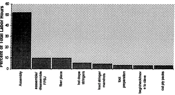
equipment, and other factors, labor was the most significant driver for cost effective materials (thermoset fabric and thermoplastic unidirectional tape). Within the labor realm, the lay-up cycle was the most significant portion of labor hours in composite fabrication (Figure 7). They also determined that automation should be used in house to make low cost materials more cost effective because the manufacturer would:
1. Increase their control of final part quality
2. Gain flexibility in tailoring the final properties of the part 3. Add value in-house rather than paying a material supplier profit
The first two items are generally accepted to be true in modern business literature: automation will have (1) more consistent quality and (2) flexibility in tailoring the final properties. Taguchi and the Japanese proved there is a cost with lower quality [30]. Flexibility allows improved products because the aircraft performance is improved. Even with military production, better products should result in increased throughput and long-term profitability. Thermoset Fabric-40.00% 35.00% 30.00% 25.00% 20.00% 15.00% 10.00% 5.00% 0.00%
Layup Bag and Autoclave Cutting Debulk Cycle
20.7 hour average, 700 parts
Figure 7: Layup is a primary source for labor costs [5, p. 71]
Foley and Bernardon may not have considered two aspects of the system: the cost of inventory and the supply chain. Inventory cost is especially important because holding cost is high and material can perish due to the shelf-life of a thermoset resin (a
manufacturer either buys expensive freezers or wastes material). Additionally, the manufacturers are typically aerospace companies which pay high wages. Lower costs at a supplier firm may reduce the total cost of production. Indeed, outsourcing has been a significant cost savings for car and computer manufacturing. Although Bernardon and Foley's analysis is excellent for 1990, future studies should consider the system costs in more detail.
1.3.3.1 Automation Processes
Various steps in the fabrication of advanced composites were described previously in this chapter. To date there has been significant automation in cutting, layup, cure, trim and inspection. Since Jenks presents a concise overview of relevant manufacturing processes in his master's thesis, this thesis does not reiterate them [12, p. 49-53]. For ease of reading, Jenk's overview table has been included as Table 5.
There are a variety of other technologies which are used at various stages of composites processing: ultrasonic and reciprocating ("gerber") cutters; honeycomb machining;
autoclave and press-forming (flow, consolidation and cure steps); waterjet, router and laser trim; and automated ultrasound part inspection.
Process Category Processes Included
Resin Transfer Molding (RTM) Vacuum-assisted Resin Injection (VARI) Preform Molding
Structural Reaction Injection Molding (SRIM) Injection Molding Reaction Injection Molding (RIM)
Reinforced Reaction Injection Molding (RRIM) Compression Molding Sheet Molding Compound (SMC)
Thermoplastic Molding (Stamping) Diaphragm Molding
Hot Transfer Press Molding
Pultrusion Axial Fibers
Multi-directional Fibers
Lamination Hand Lay-up
Automated Tape Laying (ATLM) Contoured Tape Laying (CTLM) Tow (Fiber) Placement
Filament Winding
Textile Processing Braiding
Complex 3-D Weaving Knitting
Table 5: Advanced Composite Manufacturing Processes
Table 6 summarizes the limits and capabilities of relevant lamination processes. Hand
lay-up is a labor-intensive process which can be used to effectively manufacture a large variety of shapes of limited size by laying sheets of fabric. CTLM is a high volume process which dispenses preimpregnated tape directly to a tool surface. It is excellent for
shapes with little curvature like wing-skins. Fiber placement is useful for a large variety of parts with non-constant cross sections, buildups and single and double curvature. Since filament winding is a continuous process which lays a band of tows, but it cannot add or drop tows. It is excellent for parts with circular, constant thickness cross-sections like rocket motors and liquid storage tanks for corrosive materials.
Table 6: Comparison of Lamination Processes
Table 7 gives typical lay-up rates for a variety of composite processes. This table shows
there is substantial overlap between the processes. To maximize the lay-up rate (and minimize recurring labor cost) filament winding and CTLM are excellent choices.
Unfortunately, table 6 showed that these processes are not capable of laying up as many
part shapes as hand lay-up or tow placement. ATP can manufacture the widest range of
aerospace part families, but this can sometimes be at a cost in lay-up rate as well as the
equipment is more expensive than all other options. RTM and hand lay-up are viable for smaller parts. Typical Lay-up Process Rate (b/hr) RTM .09 to .21 Filament Winding up to 100 Fiber Placement .1 to 2
Contoured Tape Layup 3 to 12 Manual Hand Layup .002 to .30
Hand Lay-up with an 2.0
automated debulk assist
Table 7: Process Lay-up Rate Comparison - typical values
At this point the reader should have an understanding of the industry, material, process flow and various types of automated fabrication techniques. The next step is to
understand more about the automated tow placement process.
1.3.4 Automated Tow Placement
The definition of ATP was given in section 1.1 and a description of shapes were listed in
Table 6. Automated tow placement is the dispensing of preimpregnated tows (or
Hand Lay-up Versatile making complex parts as large as 60 inches (due to human ergonomics). Simple parts can be made larger (the belly skin is 251 inches). Can lay buildups.
Contoured Tape Laying Limited to contours less than 15 degrees. Large size capability. Can lay buildups.
Tow Placement Capable of large parts & complex contours with non-constant cross-section, but not excessive tapers that require material placement across the tip (i.e. nose cones). Can lay buildups.
Filament Winding Capable of surfaces of revolution only. Not capable of complex contours & non-constant cross-sections without excessive weight buildup. Limited fiber orientations. Cannot lay buildups.
slit-tape) through a collimator into a band onto a tool surface. The tows can be dispensed at different rates and cut individually. Figure 8 is an artists rendering of the CMI tow placement head. The Ingersoll and the ADC heads have individual payout, controlled tension, a band collimator, tow cutters and clamps, restart rollers and a compaction roller. The Ingersoll has controlled heat for tack enhancement. These components can look very different, but the machines still dispense tows to build a part.
There are several important ATP concepts which the reader should consider: * Axes
* Steering
* Dropping and Adding Tows
· Minimum Cut Length and Boundaries
* Downtime * Software t on Fiber Placement Head Tow Restart Rollers -Collimated Fiber Band Controlled Heat
Directlon or Head I ravel
Figure 8: Artist's rendering of the fiber placement head (courtesy CMI)
Other important issues are tooling, programming and inspection. These issues are briefly discussed in section 1.5.
1.3.4.1 Axes
The CMI machine has seven axes (letters in parenthesis refer to the figure in Appendix 1): three head axes (i, j, k), a vertical arm movement (y), two horizontal arm movements (x, z) and a mandrel rotation axis (c). The Ingersoll machine has seven axes, but the head axes are roll-pitch-roll vs. CMI's yaw-pitch-roll. The ADC machine is a six-axis machine because it has only two head axes (pitch and roll). Axes are a benefit because they allow
the machine to deposit tows onto a more complex part shape, They are a hindrance
because the slowest machine axis limits the laydown speed, This is one of the reasons
why the ADC machine can lay the V-22 Grip faster than either of the other brands.
1.3.4.2 Steering
Steering a fiber band allows the fiber placement machine to map a constant fiber angle on a surface with in-plane curvature (geodesic curvature). This separates the fiber
placement machine from a CTILM machine which can only lay "natural" paths or the tape will wrinkle. Differential payout of tows as well as resin tack allow geodesic curvature.
Differential payout allows the outer tow to dispense faster than the inner tow, similar to a
tractor which slows the inner track to make a turn. Tack assists the inner fiber, under
compression, and outer, under tension, to hold to the surface.
Flory and Bernardon calculated the effect of material steering and conformability requirements on machine design as well as the composite part itself [4, p. 4-8]. They found several items:
* Acceptable steering radius increased linearly with tow width
* Compaction roller gap decreases non-linearly as the part radius increases
· Increased roller compliance reduces tow placement control
· Cutting, turning and/or retracting took 44% of total time
· Overall deposition rates can be improved more easily by reducing time spent
on non-productive operations than by increasing head speed (Flat 8' x4' part)
· Tilt-Crossfeed ATP has the broadest commercial aircraft part capability (97%)
· Lower-cost gantry tape layers cost substantially less with most of the part capability (at least 71%)
Most of these findings are in excellent agreement with the discussions on equipment tailoring and downtime in future sections. The paragraphs below explain and clarify the points outlined above.
The author can expand on Flory's and Bernardon's paper after viewing fiber placement in a production setting. They predict a substantial gap (>.05") between the roller and the
part for any part radius less than ten inches with a machine that has greater than a
one-inch bandwidth or a segmented three-inch bandwidth compaction roller with less than eight segments. Observation of BD&SG's machine suggests CMI's pneumatic compaction roller is robust to a minimum radius of about 2 inches.
Flory and Bernardon concluded that "increasing [deposition] roller compliance reduces tow placement control [4, p 6]." This is not always true. Tow placement accuracy decreases with increased roller segments, not roller compliance. Their mistake was that
they assumed roller conformance was proportional to the number of roller segments. The CMI machine has a highly conformable pneumatic roller which had little or no loss of control due to compliance when compared with a hard roller. Segmented rollers on Boeing's machine had less control than their standard pneumatic roller. Flory and Bemardon's study used a Hercules ATP machine with a solid and a segmented roller. Flory's and Bernardon's non-productive time includes cut time, turn/retract time and material load/thread time. This is not the same as the downtime as it is defined in this
thesis. The use of a flat 8' x 4' part for a comparison of productive and non-productive time is questionable because an 8' long part will never reach the 1200 ipm steady-state lay-up rate. This concept is shown by the figure in Appendix 3. Additionally, a 1200 ipm rate is not very likely because material tack presently limits laydown rates in the field
to below 800 ipm.
1.3.4.3 Dropping andAdding Tows
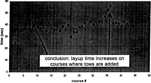
At the start and end of each course, tows need to be added and dropped, respectively. Tows need to be added when the surface area of the part increases along the surface path. They may need to be dropped if the head is traveling from a large area to a smaller area.
An example of this area change is the 0-degree orientation on the large fairing
(Appendix 4). Tow adds and drops add significantly to the lay-up time because the machine must slow to execute them. Then, it must accelerate back to speed. With
subsequent tow cuts and adds, the machine often never reaches its full program speed.
Figure 9 explains adds/drops and the minimum cut length. 1.3.4.4 Minimum Cut Length and Boundaries
The minimum cut length is the distance from the tow cutters to the lay-down point between the compaction roller and the part surface. This distance limits the coverage of the area which is desired for the ply boundary. Smaller tows will have more coverage, but increase t. complexity of the head (reduces reliability). Figure 9 shows several overlap scenarios for tows at a ply boundary (0, 50, 100%). No overlap has less coverage
but does not waste material. Complete overlap wastes a substantial amount of material, requires trim and/or increases part weight. If tows are added or dropped due to surface area changes within the ply boundary, there can be a spectrum from a triangular gap (no overlap) to a triangular overlap (complete overlap).
Designed Ply Boundry
Designed Ply Boundry Adding or Dropping Tows
(depends on lay-up direction)
.ditW
v~iig;
@
8'm'
g
9
50%
overlap
: :¢:i1;~f:fii!:.!!::-: a0 :.-- -:> % overlap 100% overlap
Cannot Lay Tows Due to MCL Figure 9: Tow Adds/Drops, MCL and Ply Boundary
:'f:':'i::':'i:c::::::!..:ii: ··,· z.rr SS:::::i:i:'':.:. ·t·r::';'l::::::·:,.,·. :.:Zi;.'I;O;SS:j.X·::.::..::er ·j·a:,,.. ::;:.is.... ;·5:Ii2:fi:· :::..::i:::..::::-..::.::f...:.::..: :.:: ·.. :iL---5::· · 1· :5;:...: · i:: :;:: ·C · "I:· i··i· ·:·i
· 5·;·; · · ;·-S·:Z Z.-:... .:,..::'::·;..·i·.·.2·:·'··.7:· :·iZ·:·r+·:··· ····:+·;·iZ 5.·· · ri:- ·· ·;···:··:·:·:·.:· ·: 5 :···L.·::···:····:···i···:···. 5 i· ';:'·s·-·. i. i·'· "''iI,:;:i:::::i-; 53 rr:ic, r;: 51 :·. ·:,':·".·-·. ijy -. , :··ts·1'·'·"' -·· ··";:';i:::::-·::·:s;·'·'; '':·::?:::;I·::i:·:::':·:::::'' 5 ·' ·:",·: :···'i,"' .; ""i': ·· 7· rl :··:
55·2:2·:::"!·)·'i·:t·.i j ji s·r:: s: :5· 5';if· 1 Q··::·::: Ii·- .?·t·. i.. ·...;s. .i·.. ....ii·.;··.:i .tn ·.· i ·:.··,:;;· · ·. ·. ..:.5.. ·: .·t .. -i-:P:i . i·.i ··';ss·:·.·.:,::·.·'t :., ·..."·.:':i;::.f:·j:iX; ·.i: · ·· ·- · · ·-· :2"';·': :·;:"::s:ii::::'Y:::::·:'·:;.: ··· V s·:i :.:·s::j.i:,R·.:,:·:·::y6q57 i···r ;':: .si...:: 'Q.·:j,:,,:· : .:::1 .... :. ..-::: :· .:.i.s:.·::.;5.::.2· 55·::i-···5·. · :::1···i···-2 i; ·· .I·"· .2·: i
1. 3.4. 5 Downtime
Downtime is a significant portion of the time on the fiber placement machine. The author and Boeing employees formed a continuous improvement team to reduce downtime. In
this thesis downtime is considered to be any time when the machine is not laying tows
that it could be, except for cuts, drops and the carriage return. The team found an average
of 44% of the time to lay a part is downtime. Downtime is discussed in more detail in
Chapter 5.
This section discussed many issues which were pertinent to manufacturing as well as design. It is now important to gain a deeper understanding of military aircraft design as it applies in HD.
1.3.4.6 Software
Machine software is critical for an automated tow placement machine. In the case of
automated tow placement it has been the deciding factor in the development of a
complete system: production was delayed for Ingersoll machines due to glitches in
software development. ADC and CMI both have robust software systems that control the process.
In general an automated tow placement software system will import surfaces and ply boundaries from a computer aided design package. These surfaces may already have been run through a finite element package to test part stress. Paths are generated from the
surfaces. Then, the NC code can be generated as well as a simulation of the ply laydown. When the completed NC codes are loaded into the control unit at the machine, the
machine has the information necessary to move the head along the tool surface.
Many of the parameters which are set during NC programming significantly effect how
the machine lays up the part as well as the rate at which it is laid. Thus, it is very
important for the programmer to understand the effects of a parameter. For example,
Appendix 3 shows the effect on lay-up rates of lay-up speed settings.
Section 1.3 introduced composites processing and focused into a description of the tow
placement prc -ess. The components of the system were introduced, but a holistic view of ATP has not yet been presented. Putting it all together, the fiber placement machine is supported by subprocesses: tooling, software and material. The material-machine
interface presents many challenges - the primary one is downtime. There is significant pre or post lay-up processing to install longerons or other details (Section 1.4.4 describes longerons) as well as adding caul plates, an isolation ply and/or copper mesh. Finally, the tool must be unloaded and the part prepared for cure.
1.4
Composites Design
This section introduces concepts in the design of advanced composite military aircraft structures. First, examples of the physical link between manufacturing and design are introduced. Second, a motivation for using data early in the decision-making process is discussed. Third, the military design process is outlined. Fourth, aircraft part families
are identified. Then, the realm of the concurrent engineering team at Boeing precedes a final discussion of ATP parts.
1.4.1 The Manufacturing-Design Linkage
The design of advanced composites is integrally linked with manufacturing due to the anisotropic properties of the laminate (a lamina is one ply, a laminate is a stack of plies).
Table 8 shows Young's modulus along the fiber direction, El, across the fibers, E2, Poisson's ratio, V12, and the torsional modulus, G12 (20], These values represent the
strength and elastic stiffness of the material in each orientation.
Property Glass/Epoxy Boron/Epoxy Graphite/Epoxy El 7.8 x 10⁶ psi 30 x 106 psi 30 x 106 psi E2 2.6 x 10⁶ psi 3 x 10⁶ psi .75 x 106 psi
V12 .25 .3 .25
G 12 1.3 x 10⁶ psi 1 x 10⁶ psi .375 x 106 psi
Table 8: Bulk Moduli for Various Laminate Orientations
Clearly, the physical properties of the part depend on the fiber orientation. Physical properties that depend on orientation are known as anisotropic properties. The fiber orientation affects the manufacture of the part. For example, a tow placement machine will lay tows at a different speed along its mandrel axis than perpendicular to this axis. This is one example of how design is physically linked with manufacturing.
The link between design and manufacturing can be extended to all parts of the composite fabrication process: lay-up, cure, trim and inspection. Trim, the process of cutting the edges of the part, is an excellent case study to enhance the link between composite design and manufacturing.
Edge Clarity Dissociation Conduction of
of Part Material Temperature Fiber HAZ size
Best Kevlar/Epoxy 500'C Low small
Moderate E-Glass/Epoxy 1250°C Moderate medium
Worst Graphite/Epoxy 3500°C High large
Table 9: Material Choice affects Trim Process Effectiveness
Table 9 shows the effect of material choice on the laser trim process effectiveness [31].
The most clear edge will be smooth and ready for inspection directly after the cut. The least clear will often need hand-sanding as a finishing process after the automated cut. A few of the items in the table require discussion. The dissociation temperature (DT) is the temperature differential between the resin melt and the fiber decomposition. For example, epoxy resin melts at about 500°C where graphite fibers vaporize at 4000C. This makes the surface of the cut very rough because resin is melting while the heat is
still being applied to cut the fiber. Additionally, the fiber conducts heat as it is being cut.
Graphite's high thermal conductivity (it is 1000 times as high as epoxy resin) melts more
resin along the fiber surface than a fiber with low conductivity. Finally, a high conductivity fiber requires additional heat input because more heat is conducted away from the cut area.
High conduction and high DT cause the heat affected zone (the zone where heat alters the properties or state of the material) to increase in size. Thus, graphite has a large HAZ. Since graphite is the most common advanced composite used for aircraft structures, applying laser cutting has been difficult. But, laser cutting is desirable because it
accurately cuts at a rate six times as fast as waterjet or router cutting. Additionally, the
laser takes less set-up time and less fixturing. With the benefits of laser cutting, it will continue to be adapted to cutting graphite/epoxy materials.
part thickness heat affected feedrate
(inches) zone (inches) (inches/second)
.040 .012 10
.070 .035 2
Table 10: Laser Cutting's link to the Part Thickness
Once graphite/epoxy has been chosen, the link between design and manufacturing does
not stop. Table 10 shows that the heat affected zone and the feedrate of the laser trim machine are affected exponentially with part thickness: they are affected by a factor of
three while the thickness does not even double. The designer should consider that an
increase in thickness will increase the time to lay up a part, to cure a part and to trim a
part. Additionally, it will add weight and material and could add a hand-finishing step. With the above example, the reader can see how material property data provided
information from which the design team can make decisions. Using manufacturing data to make design decisions about a fiber-placed part is the purpose of this thesis. The next section identifies the motivation for making educated decisions during design.
1.4.2 Motivation for good early decisions
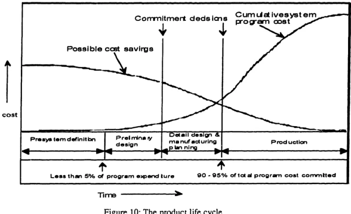
Early decisions significantly effect the life-cycle cost of the product. As shown in
Figure 10, researchers have found that companies typically spend 5% of program costs
during the initial phases of a project while committing 90% of the total program cost [2]. Instead, managers should invest resources early in the development process to realize potential cost savings while they are available. It is equally important that design teams
Conrmntmert deds ios Cum t.. ivesyst
program
oost em1· 3
Possible cost sa virgs
---. 8
Presys tem definit bn Preln minr y
design
elail design &
mea nuf acturing
_p.- ni no.
Prod uction
1.4.3
Less than 5% of program expend lure 90 - 95% of tc al program cost commtlted
Tlrre
j
Figure 10: The product life cycle
The Military Design Process
The military design process is unlike any other in industry. The development of a military aircraft can span nearly twenty years. This process has five stages:
1. Preliminary Design (-3 years) 2. Full-Scale Development (-3 years)
3. Engineering Manufacturing Development (-3 years) 4. Low Rate Initial Production (-3 years)
5. Production (-15 - 20 years)
Between each of the first four stages is a one-year period during which prototype models are extensively tested and funds are lobbied for in congress.
Preliminary Design is the initial concept of the aircraft. It is where a significant portion of the outer fuselage and aerodynamics are defined. Additionally, the "mission" for the aircraft is determined during this stage. The DoD divides missions into three groups: combat, combat support and services. Combat support can be subdivided into
aeromedical evacuation, observation, search and rescue, and assault utility vehicles. Services are primarily cargo, courier and training [1, p. I-4].
MDA's AH-64 is a multiple-engine turbine attack helicopter which fits into the combat category. Bell/Boeing's RAH-66 is an armed reconnaissance attack helicopter which also fits into the combat category. The V-22 Osprey is a tiltrotor aircraft which takes off vertically and flies like a propeller plane. Its missions are combat support and services.
cost
_ -- I
II-_ - - -
Full-scale development is where several full-scale prototype products are manufactured for testing and air worthiness. The kinks in the designs of each of the four subsystems -airframe, avionics, propulsion and weapons - are worked out during this testing. Engineering Manufacturing Development is the period where the manufacturing process
for the aircraft is developed. At this stage the government commits a significant
proportion of the product cost because aircraft manufacturers purchase tooling and equipment for the production process. For example, Boeing's Automated Tow Placement machine and its expensive Invar tooling were purchased for EMD.
Low Rate Initial Production is the phase of the project where production begins in earnest and the supplier works out the kinks in coordinating the flow of material as production increases. At this stage procedures which span for the length of the project will typically be put into place. In the case of Boeing's CH-47, many of the procedures set up during
LRIP 30 years ago were still in place as production ended in 1995.
1.4.4 Part Families
The helicopter airframe subsystem can be divided into structure, landing gear, environmental control and flight control. Within the structure sub-subsystem metal airframes and skins are being replaced with advanced composites for enhanced performance with reduced aircraft weight, fatigue and corrosion.
The author identified several "families" of composite structure which were common to HD's products. All of these, except rotors, are also common to airplanes. Rotor blades
are also not part of the airframe structure. The part fami' s are shown in Table 11. The
reader may refer to Figure 11 to gain a better understanding of where these families fit
onto an aircraft.
skins frames
fairings _ars
floors lonerons
bulkhead ribs
rotor blades angles
Table 11: Part Families observed at BD&SG, HD
Skins and fairings are typically the outer surface of the aircraft which often must meet stringent aerodynamic shape and surface smoothness requirements. In Figure 11 the belly skins and large fairings are representative of this family. They often have a significant amount of single and double curvature.
Floors and bulkheads are typically flat structures which must support the pressure of cargo or the internal pressure of a pressurized cabin, respectively. The floor of the V-22 rests on the keel framework shown in Figure 11. These parts are often thick because the flat shape must withstand the bending moments of the pressure forces.
Figure 11: the V-22 Center Section
Frames are the primary load carrying structure in the fuselage. For example, the frames at stations 369 and 422 take the vertical and shear loads from the wings (The numbers shown are station numbers which are measured in inches along the length of the aircraft.). The fuselage is a torque box which must withstand forces caused by turning as well as the pull or push of the wings (tension if the wing is top-mounted). The frames are the
primary load carrying structure for torque and compression or tension of the wing lift. Spars are the load-carrying structure which run the length of a wing or stabilizer. They are typically under an extreme bending moment, especially with the V-22 which has its engines and rotors mounted at the ends of the wings. For this reason a composite frame will typically have a significant amount of fibers oriented length-wise along the spar. Longerons, ribs and angles are all smaller load-bearing structure. Longerons, also known as stiffeners, are oriented with the length of the aircraft. They stiffen the skins by
withstanding bending loads and buckling. Ribs are the load carrying structure which runs in the airflow direction of a stabilizer or wing. They transmit the forces and moments due to lift as well as when the aircraft turns. Angles are load bearing structures which
connect parts.
The rotor blades are a critical load carrying member in a helicopter. They withstand the centrifugal forces from rotating, the bending forces of lift when in motion and their own weight when idle.
Frames, spars, longerons, angles, rotor blades and sometimes skins, ribs and bulkheads are primary load carrying structure. Primary structure sustains the critical loads of flight.


![Figure 6: Fiber Packing and Viscosity change During Cure[20]](https://thumb-eu.123doks.com/thumbv2/123doknet/14680538.559149/24.915.157.743.736.1015/figure-fiber-packing-viscosity-change-cure.webp)
![Figure 7: Layup is a primary source for labor costs [5, p. 71]](https://thumb-eu.123doks.com/thumbv2/123doknet/14680538.559149/26.915.266.689.307.592/figure-layup-primary-source-labor-costs-p.webp)