Adaline Neural Network and Real-Imaginary Instantaneous Powers
Method for Harmonic Identification
La méthode réseau de neurone Adaline et puissances instantanés
réels-imaginaires pour l'identification des harmoniques
Larbi Hamiche
1, Salah Saad
*1, Leila Merabet
1& Fares Zaamouche
21LSELM Badji-Mokhtar University, BP 12, Annaba 23000, Algeria, 2Department of Mining Engineering, Faculty of science and technology,
Larbi Tebessi University, 12000, Tebessa, Algeria
Soumis le :23/05/2017 Révisé le :14/11/2017 Accepté le : 22/11/2017
صخلم ذى ًف ا لاممنا ممعخسأ يساٌمنا طٍشننا حشزمنا تٍهعافخنا تلاطنا ضٌٌعح مجا نم ً تٍمفاٌخنا ثاراٍخنا جبك تكبشنا ًف تٍئابزيكنا . مح ًمسراٌخ زٌٌطح ة مئال دبم ىهع ة أ ًبصعنا تكبشنا ة ( نيــــلادأ ) قاطنا زٌدمخن ة تٍناٍخناً تٍمٍمحنا تٍظحهنا عم دٌدحح ثاحهطصم لا ثامٍفٌح . تٍمسراٌخنا هذى جمح ةاكاحمنا تطساٌب ًف بلاحامنا ً هذٍفنخب ا اٍبٌزجح مكحح ةدحً ًف dSPACE 1104, ثزيظأ جئاخننا ةاكاحمنا تطساٌب ايٍهع مصحخمنا كفاٌحا عم ايٍهع مصحخمنا جئاخننا اٍبٌزجح دكؤح ًخناً تٍناعف تٍمسراٌخنا هذى تحزخممنا ANN-RIIP. هذه أت تبثا ةينقتلا ن عرس و ة قد نأ نكمي نيــــلادلأا ة سحت ءادأ نم ن تطشننا تلاطنا ثاحشزم . ةيحاتفملا تاملكلا : يساٌمنا طٍشننا حشزمنا -تٍمفاٌخنا ثاراٍخنا -تكبشنا تٍبصعنا نيــــلادأ -تٌزظن “pq” -وٍـــٌرٌف تهسهس Résumé
Dans cet article, un filtre actif parallèle (SAPF) est utilisé pour la compensation de la puissance réactive et la suppression des courants harmoniques dans le réseau électrique. Un algorithme basé sur le réseau neurone(ADALINE) est développé afin d'estimer les puissances instantanées réelles et imaginaires (ANN-RIIP) et d'identifier les termes harmoniques. Cet algorithme est simulé dans l'environnement MATLAB / Simulink et implémenté expérimentalement dans un contrôleur dSPACE 1104. Les résultats obtenus par simulation sont en accord avec les résultats expérimentaux qui confirment l'efficacité de l'algorithme ANN-RIIP proposé. Cette technique a démontrée que la vitesse et la précision d’ADALINE peuvent améliorer les performances des filtres actifs de puissance.
Mots Clés: filtre actif parallèle – courant harmonique – réseau de neurone Adaline – la théorie “pq”- séries de
Fourier
Abstract
In this paper, a shunt active power filter (SAPF) is used for reactive power compensation and harmonic current suppression. Algorithm based on (ADALINE) Neural Network and Real and Imaginary Instantaneous Powers (ANN-RIIP) is developed in order to estimate and identify the harmonic terms individually and online. This algorithm is simulated in MATLAB/Simulink environment and implemented experimental in a dSPACE 1104 controller. The results obtained by simulation are in agreement with the experimental results confirming the effectiveness of the proposed ANN-RIIP algorithm. The results have also demonstrated that the speed and accuracy of ADALINE can improve the performances of active power filters.
Keywords: Active Power Filter - Harmonics Currents -ADALINE Neural Network -“pq” theory - Fourier
series.
1. INTRODUCTION
Harmonic current identification (detection) is the issue to solve in order to improve the harmonic current compensation effects of Shunt Active Power Filter (SAPF). It is also important to select a suitable controller technique to obtain a better compensation capability of SAPF. Harmonic current suppression and semiconductors protection depend greatly on harmonic current control and on stability of the inverter dc voltage. Thus, the control of dc voltage is necessary to keep its value constant and limit the fluctuations in order to prevent semiconductors from failures. That is to look for a controller which is insensitivity to parameters variation and disturbances and also appropriate to parameters closed loop control such as shunt active power filter harmonic current identification and inverter dc voltage control. Therefore many controllers were used and applied for this purpose. An improved tracking technique of the reference current waveform (harmonic current) in a SAPF is proposed [1, 2] using sliding mode control, feedback linearization, and fuzzy logic controller to reduce the complexity of the controller. The compensation capability mainly depends on the regulation of DC link capacitor voltage. Conventionally this voltage regulation is achieved by the closed loop operation of Proportional Integral (PI) controller [2, 3]. To improve the performance of SAPF neural learning algorithm techniques were proposed [4, 5]. The reference current is fed to the hysteresis current controller and compared with the sensed filter currents to obtain the switching signal for active power filter (inverter) [6]. To enhance the performance of the conventional controller and to take advantage of intelligent controllers, a back propagation algorithm based feed forward-type Adaline Neural Network (ANN) technique is implemented in shunt active power filter for producing the controlled pulses required for IGBTs of the inverter [3], [7]. The compensation process proposed is based on sensing line currents and regulating the dc link voltage.
The use of neuronal networks in the field of power electronics is becoming more common because of their ability to learn nonlinearities. In fact, several techniques based on Adaline Neural Networks (ANN) [8], [9], [10] and other intelligent techniques [3], [11] have been developed to estimate, identify, and control harmonic currents in power systems and some results where compared to conventional PI controllers. These works have showed the high performances of shunt active power filter when intelligent techniques are used.
A combined ANN based predictive and adaptive reference generation technique was used [12] where predictive scheme extracts the information of the fundamental component through an ANN that replaces a low pass filter. It has been shown that the combined predictive adaptive approach offers better performance. The predictive and adaptive properties of ANNs are also used for fast estimation of the compensating current [13]. The novelty control design is an Artificial Neural Network (ANN) adopting a modified mathematical algorithm and a suitable alpha value (learning rate value) which determines the filters optimal operation [14]. The compensation process proposed in [15] is based on sensing source currents and regulating the dc link voltage. A high performance extraction algorithm coupled with a fast switching technique was developed [16] introducing a new effective algorithms to identify and generate the necessary compensation signal injected on to the power networks.
From the previous works it can be concluded that static converters are extensively used in the industry and generate non-sinusoidal currents and disrupt the electrical grid. This poses some problems to distributors and users of electric power. The active power filter has been widely used, studies and presented as a solution to overcome the harmonics issues. Their response is instantaneous and copes automatically with changing disturbances introduced by nonlinear loads of electrical power systems. The aim of the present paper is to identify harmonics in order to obtain an ideal compensation when shunt active power filter (SAPF) is used to mitigate harmonic currents. A study of harmonic currents identification is conducted by a method based on Adaline Neural Network and Real-Imaginary Instantaneous Powers (ANN-RIIP). This technique requires less computational time compared to other classical techniques especially the methods based on real and imaginary instantaneous power (pq theory). The proposed method can estimate the total harmonic currents and the harmonic components
independently realizing a selective compensation. The method is also easy to implement in real time applications compared to other classical methods.
The results obtained by simulation in MATLAB / Simulink environment and real time implementation on experimental platform equipped with dSPACE 1104 microcontroller have showed the efficiency and the robustness of the proposed method in harmonic currents and reactive power compensation.
2. MATERIAL AND METHOD
The main role of the shunt active power filter (SAPF) is to inject an appropriate current (If) into the
system to compensate harmonic currents that are responsible for power network pollution. This SAPF is a voltage source inverter connected to the three-phase line through the inductor Lf as presented in
Figure 1. It consists of an inverter based on IGBT power switches with anti-parallel diodes, a coupling filter and a passive element for storing energy, often the capacitor is used for this purpose.
Figure 1: Shunt active power filter operation
The inverter switches control is based on pulse width modulation (PWM) technique applied to the reference current (harmonic current). Thereafter, this current (reference current) is compared with a triangular signal (carrier), the obtained pulses control the inverter switches.
The active filter generates harmonic currents of the same magnitude as those of the network, but in opposite phase.
3. ESTIMATION OF REAL AND IMAGINARY INSTANTANEOUS POWERS (RIIP) BY ADALINE NEURAL NETWORKS
It is important to recall here that the most used method for harmonic current identification is the instantaneous active and reactive power theory. In 1983 Akagi. Konazawa and A. Nabae [17] introduced this theory also called “p-q theory”, where p is the real power and represents the total energy flow in the three-wire three-phase system; q is the imaginary power and has a non-traditional physical meaning and gives the measure of the quantity of current or power that flows in each phase without transporting energy at any instant.
This theory is mainly used for the generation of reference current of reactive power compensator, because it defines the power clearly.
Identification is the first step consists on transforming voltages and currents of three phase frame (a, b, and c) to diphase frame, using Concordia direct transformation.
In the presence of harmonics, the apparent power is composed of three parts active power, reactive power and deforming power as expressed below.
S2= P2+ Q2+ D2 (1)
S = apparent power, P = active power, Q = reactive power, D = deforming power
Noting the line to neutral voltages and three-phase system line currents without zero-sequence by (Vsa,
Vsb, Vsc) and (Isa, Isb, Isc). vα vβ = 2 3 1 −1 2 −1 2 0 3 2 − 3 2 va vb vc (2) Where,
Vsa, Vsb, and Vsc are the line to neutral voltages of phase a, b, and c respectively
iα iβ = 2 3 1 −1 2 −1 2 0 3 2 − 3 2 ia ib ic (3)
Where, Isa, Isb, Isc are the line currents of phase a, b, and c respectively
The instantaneous real power p and instantaneous reactive power q can be expressed equivalently in diphase system and expressed as follows:
p q =
vα vβ
−vβ vα iiαβ (4)
Where, vα, vβ voltages in α and β frame
This will give: p = vq = vα. iα + vβ. iβ
α. iβ− vβ. iα (5)
Where, iα, iβ currents in α and β frame
The p and q can be decomposed as: p = p + p
q = q + q (6) Where,
𝑝 and 𝑞 are the active and reactive average powers respectively, corresponding to the load fundamental current (50 Hz) while, 𝑝 and 𝑞 correspond to the alternative compounds related to harmonic currents.
The generation of the total harmonic currents is carried out by SAPF and injected into the ac source and thus the compensation is obtained.
Consequently, the elimination of the fundamental compound is realized by two low-pass filters. From the equation (3) giving the real and imaginary instantaneous powers, the following current equation is derived: iα iβ = 1 vα2+ vβ2 vα −vβ vβ vα p q (7)
Considering, the equations (5) and (6), the current can be separated in (α-β) frame in three compounds (active and reactive at the fundamental frequency and the harmonics). This will lead to the equation obtained below:
iα iβ = 1 ∆ vα −vβ vβ vα p 0 +1 ∆ vα −vβ vβ vα 0q + 1 ∆ vα −vβ vβ vα p q (8) With
:
∆= 𝑣𝛼2+ 𝑣𝛽2This expression allows the identification of the current references in the (α-β) frame. Then the three phase currents are obtained from diphase currents iα and iβ by the inverse of Concordia
transformation: irefa irefb irefc = 2 3 1 0 − 1 2 3 2 − 1 2 − 3 2 iα iβ (9) Where,
irefa, irefb, irefc are the current references in the (α-β) frame.
3.1 Neural-RIIP (Real and Imaginary Instantaneous Powers) method
This method consists on replacing the two low-pass filters of RIIP method by two ADALINE networks. Figure 2 shows the two ADALINE networks used to identify harmonic current. The first step is to compute the active and reactive powers (p and q) in diphase frame by the equations (1), (2) and (3). Then, validation of the proposed Neural-RIIP technique applied for harmonic current identification by simulation and real time implementation before the compensation.
The experimental and simulation tests are conducted following the workflow diagram shown in Figure 3. This procedure presents how the algorithm is applied to identify harmonic currents. First the measured voltages and currents of network source are visualized through dSPACE microcontroller, and then the instantaneous real and imaginary powers (pq) are calculated using Concordia transformation.
Secondly another algorithm developed in Matlab Simulink environment based on Adaline Neural Network (ANN) is applied to estimate the instantaneous real and imaginary powers (pest qest) as shown in Figure 2.
This algorithm is developed as presented in the section below (theoretical development of Adaline Neural Network algorithm) and explained in [5]. From these estimated powers the harmonic currents are calculated through Concordia inverse transformation (diphase to three phase transformation) and current of references (harmonic currents) are obtained. Finally harmonic currents can be used as references for PWM (pulse width modulation) to generate gates control signals to control the inverter switches.
Figure 2: Two ADALINE networks used to identify reference current
Figure 3. Experimental workflow diagram Measurement of
voltages (Vsabc) and
currents (Isabc) of electrical networks Concordia Transformation (3/2) Concordia inverse transformation (2/3) Signal converter Matlab Environment
Calculation of instantaneous power (pq) ADALINE for (pestimation) ADALINE for (qestimation) Calculation of Harmonics Currents Calculation of reference currents (Irefa, Irefb, Irefc)
ADC (Analogue Digital
Converter)
3.2 Theoretical development of ADALINE neural network algorithm
In order to estimate the real and imaginary instantaneous powers, it is possible to decompose the currents ISabc and voltages VSabc of an electric network into a Fourier series as follows:
Isabc t = In1cos n ωt − α n=1,….,N + In2sin n ωt − α (10) Vsabc t = Vn1cos nωt n=1,….,N + Vn2sin nωt (11) Where,
- ω : The fundamental frequency of the electrical network
- In1 , In2: The amplitudes of the sine and cosine components of network current
- α: Phase angle between current and voltage
- Vn1, Vn2 : The amplitudes of the sine and cosine components of the main voltages
Using a frequency analysis, the expressions (6) of the instantaneous powers is developed:
p = p1cos α + p5cos 6ωt − 5α − p7cos 6ωt − 7α − ⋯ (12) q = − q1sin α − q5sin 6ωt − 5α − q7sin 6ωt − 7α + ⋯ (13)
p1cosα, -q1sinα represent the continuous parts (𝑝 ,𝑞 ) and the rest of terms represent the alternative
parts (𝑝 , 𝑞 ). To estimate active and reactive powers, two Adaline are developed, where the inputs are sinusoidal functions that correspond to each harmonic order in the mathematical developments shown in equations (12) and (13).
The Fourier analysis can express the instantaneous real and imaginary powers in the general case as follows: f t = A0+ An1cos nωt − n − 1 α n=1,…,N + An2cos nωt − n + 1 α + Bn1sin nωt − n − 1 α + Bn2sin nωt − n + 1 α (14)
Where, A0 represent the continuous part, An1, An2, Bn1, Bn1 the amplitudes of the sinus and cosines.
f t = WT. x t
(15)
WT is the weight vector of the network, and x(t) is its input
WT = A0A11A12B11B12… AN1AN2BN1BN2 (16)
and,
𝑥 𝑡 = 1 cos 6𝜔𝑡 − 5𝛼 sin 6𝜔𝑡 − 5𝛼 cos 6𝜔𝑡 − 7𝛼 sin 6𝜔𝑡 − 7𝛼 . .. cos 𝑛𝜔𝑡 − 𝑛 − 1 𝛼 sin 𝑛𝜔𝑡 − 𝑛 − 1 𝛼 cos 𝑛𝜔𝑡 − 𝑛 + 1 𝛼 sin 𝑛𝜔𝑡 − 𝑛 + 1 𝛼(17)
The product of equation (15) can then be implemented by neuron, where WT is the weight vector of the network and x (t) its input. Figure 4, shows this instantaneous power topology for p reel power (which is the same topology for q imaginary power) to be compensated by two ADALINE as illustrated in the figure below.
The input number corresponding to (m=h/2 -1) with the desired number of harmonics to identify. (q) is the signal of reactive power identified by its components, (qest) is the power signal estimated by
Adaline network, the error (e) is the difference between (q) and (qest) power signals. In order to update
the neural weights the learning algorithm (Widrow-Holf ) is used:
W k + 1 = W k + μ e k . x k (18) W k Neural weight at (k) time
e(k) the error at (k) time
x(k) the input vector at (k) time
µ is the learning coefficient
(
q), (qest) are the reel and the estimated reactive powers respectively Widrow-Holf algorithm is theleast mean square (LMS) algorithm applied in adaptive signal processing and adaptive control to calculate the weights.
4. SIMULATION AND EXPERIMENTS
In order to confirm the developed algorithm simulation and experimental tests are conducted using a program working in MATLAB Simulink environment and dSPACE controller respectively. Computer simulations are carried out to validate the ANN-RIIP developed algorithm and evaluate the performances of this method in harmonic currents identification under industrial operating conditions. The studied system is fed from a balanced three-phase voltage sources feeding a three-phase diode bridge rectifier with inductive load. The simulation and experimental parameters are given in Table.1.
Supply:Vs, Rs, Ls 220V,0.5, 2.0 mH. DCLoad: RL, LL 10 Ω, 20 mH DC supply voltage Vdc 750V Filter inductances Lf , rf 0.0003 H , 0.05 Switching frequency 10KHZ
Current sensor gain K=10
Table.1. Simulation Parameters
An experimental platform is designed to validate and confirm the results obtained by computer simulation and evaluate at the same time the performances of ANN-RIIP technique.
The real-time applications on the dSPACE DS1104 are carried out using Real-Time Interface in MATLAB/Simulink environment. The visualization of system waveforms is realized through CONTROL DESK software, enabling to control the signals from Simulink dSPACE schemes. Figure 4 illustrates the experimental setup used to conduct the experimental tests.
Figure 4: Experimental setup
The modulation frequency used in this work is 10 KHz. for fast response the learning rate has been tested and chosen equal to 0.01. This value is motivated by several tests and the input types of the Adaline which are the cosine and sine as illustrated in Fig.2 (they vary between -1 to +1). In this application, the program of the ANN-RIIP technique is written in C++ code. The Current and voltage
sensors have a reduction factor equal to 10. Therefore, real current and voltage measurement are 10 times greater than the values taken during simulation and experimentation.
5. RESULTS AND DISCUSSIONS
The results of simulation tests are presented in the following figures. The measured load current before the compensation is illustrated in Figure 5. The load current has the classical quasi-square wave shape before compensation.
While the reference current (harmonic current) extracted by ANN-RIIP method is shown in Figure 6. The harmonic currents considered on the inputs of the two ADALINE for Diphase Current Method are the 5th, 7th, 11th, 13th, and 17th
Figure 6: The identified harmonic currents using ANN-RIIP method
.
The results of experimental tests are presented below. Figure 7 is the measured load current before the compensation and Figure 8 is the identified harmonic currents. It can be seen that with this method it is possible to estimate the harmonics individually and all harmonic currents considered in the inputs of the two Adaline.
In order to evaluate the performance of the proposed ANN-RIIP method, the waveforms representing the source current and the harmonic current frequency spectrum are measured.
The results obtained by the proposed ANN-RIIP extraction method presented in Figure 5, 6, 7, and 8 have showed a great efficiency in harmonic identification. The waveforms illustrating the measured load current before the compensation Figure 5 and the reference current (harmonic current) extracted by ANN-RIIP method Fig.6 are identical to the experimental waveforms shown in Figure 7 and Figure 8 respectively. It can be seen that it is possible to estimate the harmonic current individually and/or all harmonic currents considered in the inputs of the two Adaline.
Figure 7. Measured load current before compensation
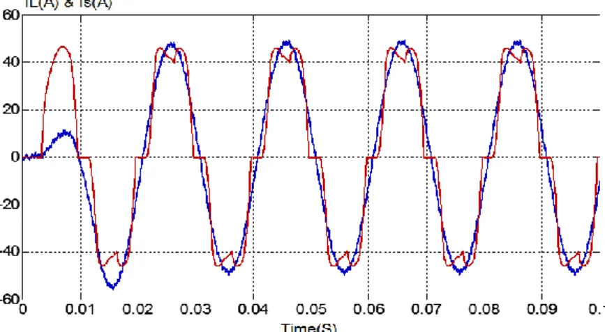
Figure 9 shows the measured load and source current and Figure 10 illustrates the harmonic source current frequency spectrum.
The effectiveness of the proposed method is evaluated by measuring the current of the main source and its frequency spectrum. The waveform of this current is sinusoidal as shown in Figure 9 and the calculated total harmonic distortion (THD) Figure 10 is 1.48%. This value is well below the IEEE recommendations (5%) showing that a good identification is obtained when ANN-RIIP is used for harmonic current identification.
Figure 9: The measured load and source current
Figure 10. Harmonic source current frequency spectrum
6. CONCLUSION
In this work the ANN-RIIP technique is proposed as a contribution for harmonic currents identification in order to obtain an ideal compensation when shunt active power filter (SAPF) is used to suppress harmonic currents generated by nonlinear loads.
Simulation and experimental results have showed that the power quality is improved and an accurate harmonic current identification is achieved with ANN-RIIP technique. It is also important to notice that it is possible to estimate the total harmonic current and individual harmonic current therefore a selective compensation can be obtained. The effectiveness of the proposed method is evaluated by THD measurement which is well below the IEEE recommendations and the waveform of the source current is sinusoidal.
7. REFERENCES
[1] Anirban S. R., Avik B.,2016, Improved tracking of shunt active power filter by sliding mode control , Electrical Power and Energy Systems, 78, p. 916–925.
[2] Saad S., Zellouma L., 2009,Fuzzy logic controller for three-level shunt active filter compensating harmonics and reactive power, Electric Power Systems Research, 79 p.1337–1341.
[3] Saad S., Zellouma L., Herous L,2008,Comparison of Fuzzy Logic and proportional Controller of Shunt Active Filter Compensating Current Harmonics and Power Factor, 2nd International Conference on Electrical Engineering Design and Technology ICEEDT08, Hammamet Tunisia, November 8-10.
[4] Senthilkumar A, Poongothai. Kb, Selvakumar. Sc, Silambarasan. Md, P. Ajay-D-VimalRaje, 2015, Mitigation of Harmonic Distortion in Microgrid System using Adaptive Neural Learning Algorithm based Shunt Active Power Filter, Procedia Technology, 21, p. 147 – 154.
[5] Merabet L., Saad S., Ould Abdeslam D., Omeiri A.,2013, A comparative study of harmonic currents extraction by simulation and implementation, Electrical Power and Energy Systems, 53, p. 507–514.
[6] Juwairiah M. J., Wahyu M. U., Mohd Abdul Talib M. Y., Mohd E. M, 2014, Artificial Neural Network Controller for Single-Phase Active Power Filter, IEEE, p. 978-1-4799-4848-2/14.
[7] Jarupula S., M.Venu Gopala Rao. ,2014, Power Conditioning in Distribution Systems Using ANN Controlled Shunt Hybrid Active Power Filter, IEEE, p. 978-1-4799-4103-2/14.
[8] Dhanavath, S.P. Singh, 2014, Inter leaved buck converter based active power filter control using artificial neural network, International Conference on Power Electronics, Drives and Energy Systems (PEDES), IEEE.
[9] Hu Qing, Guo Qingding, Yu Dongmei and Liu Chunfang, 2005, A Novel ANN-based Adaptive Harmonic Current Detecting Method for Active Power Filters, IEEE/PES Transmission and Distribution Conference & Exhibition: Asia and Pacific Dalian, China.
[10] Yongtao, Dai1, Wenjin, Dai, 2008, Harmonic and Reactive Power Compensation with Artificial Neural Network Technology, World Congress on Intelligent Control and Automation June 25 - 27, Chongqing, China.
[11] Sindhu M. R., Manjula G. Nair, and T. N. P. Nambiar,2008, An ANN based Digital Controller for a Three-phase Active Power Filter, IEEE, p. 978-1-4244-1762-9/08.
[12] Avik Bhattacharya, Kharagpur Kharagpur, 2008, Predictive and Adaptive ANN (Adaline) Based Harmonic Compensation for Shunt Active PowerFilter , IEEE Region 10 Colloquium and the Third ICIIS, Kharagpur, INDIA. [13] Avik Bhattacharya., Chandan Chakraborty, February 2011, A Shunt Active Power Filter With Enhanced Performance Using ANN-Based Predictive and Adaptive Controllers, IEEE Transactions on Industrial Electronics, February 2011, Vol. 58, No. 2.
[14] Aliyu Sabo, Noor Izzri Abdul Wahab, Mohd Amran Mohd Radzi, Nashiren Farzilah Mailah,2013, A Modified Artificial Neural Network (ANN) Algorithm to Control Shunt Active Power Filter (SAPF) for Current Harmonics Reduction, IEEE Conference on Clean Energy and Technology (CEAT).
[15] Dhanavath Suresh., S. P. Singh,2014,Performance investigation of the shunt active power filter using neural network, IEEE Students, Conference on Electrical, Electronics and Computer Science.
[16] Aliyu Sabo, Noor Izzri Abdulwahab, Mohd Amran Mohd Radzi, Nashiren Farzilah Mailah, (online), A Modified Digital Hysteresis and Artificial Neural Network (ANN) Algorithms in Single Phase Shunt Active Power Filter Control. Available at: http://ieeexplore.ieee.org/document/6873789/?tp=&arnumber=6873789.
[17] Akagi, H., Kanazawa, Y. and Nabae, A,1984,Instantaneous Reactive Power Compensator Comprising Switching Devices Without Energy Storage Components, IEEE Trans. Ind. Appl, vol. IA-20, no. 3, pp. 625-6.