HAL Id: hal-01963794
https://hal-amu.archives-ouvertes.fr/hal-01963794
Submitted on 21 Dec 2018
HAL is a multi-disciplinary open access
archive for the deposit and dissemination of
sci-entific research documents, whether they are
pub-lished or not. The documents may come from
teaching and research institutions in France or
abroad, or from public or private research centers.
L’archive ouverte pluridisciplinaire HAL, est
destinée au dépôt et à la diffusion de documents
scientifiques de niveau recherche, publiés ou non,
émanant des établissements d’enseignement et de
recherche français ou étrangers, des laboratoires
publics ou privés.
Coupling Cortical Neurons through Electronic
Memristive Synapse
Elvira Juzekaeva, Azat Nasretdinov, Silvia Battistoni, Tatiana Berzina,
Salvatore Iannotta, Rustem Khazipov, Victor Erokhin, Marat Mukhtarov
To cite this version:
Elvira Juzekaeva, Azat Nasretdinov, Silvia Battistoni, Tatiana Berzina, Salvatore Iannotta, et al..
Coupling Cortical Neurons through Electronic Memristive Synapse. Advanced Materials Technologies,
Wiley, 2018, pp.1800350. �10.1002/admt.201800350�. �hal-01963794�
COMMUNICATION
www.advmattechnol.de
Coupling Cortical Neurons through Electronic
Memristive Synapse
Elvira Juzekaeva, Azat Nasretdinov, Silvia Battistoni, Tatiana Berzina, Salvatore Iannotta,
Rustem Khazipov, Victor Erokhin,* and Marat Mukhtarov
DOI: 10.1002/admt.201800350
of electrophysiological spike-sorting[4] and
optogenetic[5] approaches enables an
effi-cient readout and control over activity of single or groups of neurons leading to a development of prosthetic devices. For example, fMRI-guided electrophysiological recordings of single motor cortex neurons involved in specific motor tasks combined with muscle electrostimulation enabled to produce prosthesis with a remarkable alleviation of the neurological deficits in hemiplegic patients with a traumatic lesion of synaptic connections between the corticospinal neurons and motor neurons in spinal cord.[6] Restoration of synaptic
connections as in the case of traumatic injury above as well as in other patholo-gies associated with a synaptic loss of function and various synaptopathies could be also solved through an introduction of electronic synapses to connect neurons directly, given that these artificial synapses recapitulate the main feature of natural synapses including their plasticity. Moreover, development of electronic synapses with unprecedented, due to biological restraints, features during evolution could result in creation of cyborgs with unprecedented capacities.
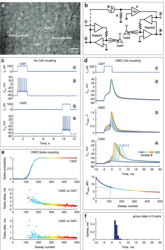
We used patch-clamp recordings from nonconnected pairs of cortical layer 5 pyramidal neurons in rat brain slices (Figure 1a). Action potentials (APs) evoked by suprathreshold depolarizing current injection in either neuron failed to evoke any response in another cell in the pair (Figure 1c), indicating that these cells were not connected by natural synapses in either direc-tion. These neurons were then connected through an electronic circuit with an OMD, playing the role of a synapse analog (Figure 1b). The structure of the OMD included a conducting polymer—polyaniline (PANI), with a solid electrolyte—lithium salt doped polyethylene oxide (PEO), and its memristive fea-tures were based on the high difference in PANI conductivity in the oxidized and reduced forms.[7,8] The ratio of PANI
con-ductivity in oxidized and reduced forms is in the order of 108.[8]
However, the need to have a medium for these reactions reduces the maximum reported ratio for the entire device till about 105.[9] After setting the OMD resistance initially at high
values by negative voltage loading (Figure 1d, bottom), APs in a “presynaptic” Cell 1 (Figure 1d, plot 2) were induced by a suprathreshold depolarizing steps (Figure 1d, plot 1). However, these APs in Cell 1 evoked only a subthreshold depolarizing response in the “postsynaptic” Cell 2 (Figure 1d, plot 4, the first
Functional coupling live neurons through artificial synapses is the primary
requirement for their implementation as prosthetic devices or in building
hybrid networks. Here, the first evidence of unidirectional, activity dependent,
coupling of two live neurons in brain slices via organic memristive devices
(OMD) is demonstrated. ODM is a polymeric electrochemical element,
which has two terminals for the connection in electrical circuits and which
displays hysteresis and rectifying features. OMD coupling is characterized
by nonlinear relationships determined by the instantaneous values of OMD
resistance that can be controlled by the neuronal activity, and the excitation
threshold in the postsynaptic neuron. OMD coupling also has the
spike-timing features similar to that of the natural excitatory synapses. Also,
OMD-synapses support synchronized delta-oscillations in the two-neuron network.
It is proposed that OMD-synapses may enable realization of prosthetic
synapses and building hybrid neuronal networks endowed with a capacity of
learning, memory, and computation.
E. Juzekaeva, A. Nasretdinov, Prof. R. Khazipov, Dr. V. Erokhin, Dr. M. Mukhtarov
Laboratory of Neurobiology
Institut of Fundamental Medicine and Biology Kazan Federal University
Kremlevskaya 18, 420008 Kazan, Russia E-mail: [email protected]
Dr. S. Battistoni, T. Berzina, Dr. S. Iannotta, Dr. V. Erokhin Institute of Materials for Electronics and Magnetism Italian National Council of Research (CNR-IMEM) Parco Area delle Scienze, 37A, 43124 Parma, Italy Prof. R. Khazipov
INMED INSERM UMR1249 Aix-Marseille University
163 Avenue de Luminy, BP 13, 13273 Marseille Cedex 09, France The ORCID identification number(s) for the author(s) of this article can be found under https://doi.org/10.1002/admt.201800350.
Synapse Prosthesis
A synapse is a biological structure, which connects two neu-rons enabling specific and unidirectional information flow (excitation or inhibition) from one neuron to another. Synaptic connections are the key elements of the neuronal networks and their plasticity underlies learning and memory. Recent progress in building artificial neuronal networks is largely based on the elements mimicking features of natural synapses in silico or in electrico.[1–3] Hybrid networks, in which
brain-computer systems read and control the activity of live cells also require interphase devices with cellular resolution. Use
www.advancedsciencenews.com www.advmattechnol.de
Figure 1. Activity-dependent coupling of neurons by OMD. a) Infrared differential interference contrast microphotograph of a P7 rat brain slice with
visually identified L5/6 neocortical cells (Cell1,2) recorded simultaneously. b) Simplified electrical scheme of two patch-clamp amplifier headstages (Patch1,2): 1,3—patch-clamp holding inputs; 2,4—patch-clamp primary outputs; and an OMD-based circuit (5 × 5 mm) connecting two neurons. c,d) Traces of current-clamp recordings from Cells 1 and 2 before c) and after d) OMD-coupling. Traces 1–4 correspond to the inputs/outputs as labeled in b. Note that prior to OMD-coupling (c) APs in either neuron failed to evoke responses in the other neuron, indicating that these cells were not connected by natural synapses. After connection of Cells 1 and 2 through OMD (d), the efficacy of coupling progressively increases with each consecutive depolarizing step/AP in Cell1. 500 traces (color coded by sweep #) are aligned with suprathreshold depolarizing steps delivered to Cell1. Bottom plot, OMD resistance as a function of the sweep #. Dashed lines indicate the first sweep when Cell2 started firing. e) Corresponding plots of the activity-dependent change in spike probability in Cell2 (top), spike delay of Cell2 from Cell1 (middle) and spike delay jitter in Cell2 (bottom). f) Histogram of the spike delay in Cell2 from Cell1 calculated for three OMD-coupled cell pairs (777 spikes).
www.advancedsciencenews.com www.advmattechnol.de
blue color coded sweeps) due to high initial OMD resistance (Figure 1d, bottom panel and 1e, top panel). Since the OMD resistance reduces upon depolarization,[10] the consecutive
depolarizing steps and the APs in Cell 1 induced a gradual increase in voltage responses from the OMD (Figure 1d, plot 3) and in Cell 2 (Figure 1d, plot 4). When the OMD resistance decreased by a factor ≈2 (Figure 1d, bottom, sweep #113), the depolarizing response in Cell2 reached the AP threshold (≈−40 mV) and Cell 2 started reliably fire APs (Figure 1d, plot 4, sweep #113 onwards and Figure 1e). Along with a further decrease in OMD resistance (Figure 1d, bottom), the firing probability of Cell 2 gradually increased (Figure 1e, top). The activity-dependent increase in spike coupling between neurons was also associated with an improvement in the spike-timing through the OMD synapse as evidenced by a progressive reduc-tion in the AP delays (Figure 1d, plot 4 and Figure 1e, middle plot), and a reduction in the jitter of AP delays (Figure 1d, plot 4 and Figure 1e, bottom plot).[11,12] Figure 1f shows the
histo-gram summarizing the delay times of Cell2 spiking from t Cell1 for three cell pairs (777 spikes recorded). It is noteworthy that the characteristic timing of the AP commutation through the OMD-synapse is similar to that of natural excitatory synapses.[13]
To further assess the synaptic response, we also examined whether OMD coupling could enable neuronal synchroniza-tion during spontaneous activity. To this end, presynaptic Cell1 was continuously depolarized by injection of constant inward current to allow spontaneous firing (Figure 2a, blue trace). We observed that the firing of Cell1 induced a gradual decrease in OMD resistance (Figure 2d, bottom) which in turn induces an increase in Cell2 responses as in the experiments above (Figure 2a, red trace). As soon as the suprathreshold level of cell coupling was achieved, Cell2 started firing APs in syn-chrony with Cell 1 (Figure 2a,d), yet with a 3.8 ± 0.1 ms time lag (n = 3 cell pairs, 633 spikes recorded; Figure 2e). Synchronized firing of the OMD-coupled neurons occurred in the δ-frequency range (0.56 ± 0.04 Hz, n = 3 cell pairs; Figure 2b,c) that is char-acteristic of the slow-wave cortical activity during deep sleep.[14]
In this study, we provide for the first time experimental evidence of the unidirectional, activity-dependent, coupling of live neurons through the organic memristive device (OMD). We demonstrate that the spike-timing features of the OMD-synapse approach those of the natural excitatory OMD-synapses, that the magnitude of OMD-coupling can be controlled by the neuronal activity, and that OMD synapses efficiently support neuronal synchronization, in a simple two-neuron network.
Electronic devices (organic and inorganic) have been used to record extracellular field changes,[15] cellular action potential[16–18]
and in vivo electrophysiological recordings.[19] Despite its large
interest, the realization of prototype of artificial synapse chips is mostly focused on the controlled release of chemical com-pounds[20] through micropatterned substrates[21,22] more than on
the creation of a functional interface between devices and cells. Such kind of connection must allow the signal transmission between cells and device and, most important, the transmission of stimulations between groups of cells through the device. There are several works, where silicon circuits were used for mim-icking synapse functions.[1,2] Recently, memristive devices[23,24]
have been used as electronic analogs of synapses.[25,26] Several
memristor-based circuits have demonstrated plasticity suitable
for artificial neural networks,[27,28] mimicked the learning of
simple animals,[29,30] and been used for the acquisition and partial
decoding of signals from retina.[31] However, the evidence that
memristors could functionally couple live neurons is still missing. This is the primary requirement for their implementation in pros-thetic devices or in building hybrid networks that requires the use of special materials in adequate configurations. Furthermore, if we consider the perspective of implantable systems, one must ful-fill requirements such as biocompatibility, flexibility, and stretch-ability. In this framework here, we demonstrate a quite novel functionality with the first evidence of unidirectional, activity-dependent coupling of two live neurons in brain slices via OMDs. OMD coupling is characterized by nonlinear relationships deter-mined by the instantaneous resistance of OMD depending on the connected neuronal activity, and by the observed excitation threshold in the postsynaptic neuron. We demonstrate that the OMD coupling shows also spike-timing features similar to those typical of natural excitatory synapses. Furthermore our OMD-synapses efficiently support synchronized delta-oscillations in the two-neuron network. All such features, ever observed simultane-ously in such a simple single device, make OMD-synapses eligible for a significant step toward the realization of prosthetic synapses.
For considering these devices as elements for synapse pros-thesis some major important properties are required: 1) they must show plasticity in signal transmission emulating that typical in living beings; 2) for implants, devices must be flexible and made of biocompatible materials; 3) size of the elements must be com-parable with cell dimensions; 4) interconnections and external electronics system should not significantly disturb the functioning of the nervous system. Each of these features requires appropriate studies and optimizations. For items 2) and 3), there are already positive solutions. In fact, since the early works it has been shown that OMD can be realized in a flexible configuration.[9] As far as the
biocompatibility of the materials for OMD is concerned, it has been demonstrated in experiments of growth of cells[32,33] and simple
organisms[34–36] on their surface. Moreover, the active channel can
be fabricated by the so-called layer-by-layer technique,[37] allowing
the formation of architectures, where all the parts in contact with the biological surrounding are made of biocompatible polymers.[38,39]
Requirement 3) has also been demonstrated, showing the scal-ability of the OMDs[40] by fabricating devices with lateral sizes of
20 µm[41] that can be scaled further, as it was shown to be possible
the realization of submicron organic electronic systems.[42]
Thus, the major challenges concern properties 1) and 4) that requires further studies and developments. In particular, the question of interconnects and external electronics 4) is very critical in the case of brain implants, a subject of large efforts by several groups.[1,2,43]
The aim of this work is to address and contribute to develop the major requirement 1) hence concentrating our efforts to demonstrating, for the first time directly, that OMDs can have the same plasticity of electrical properties of the chemical syn-apses in living beings.
The major outcome of this study is that we provide experimental evidence of unidirectional, activity-dependent coupling of live neu-rons through an organic memristive device. We demonstrate that the spike-timing features of the OMD-synapse are very similar down to several details to those of natural excitatory synapses, that the magnitude of OMD-coupling can be regulated by neuronal
www.advancedsciencenews.com www.advmattechnol.de
activity, and that OMD synapses efficiently support neuronal syn-chronization in a simple two-neuron network. We therefore give important indications that OMDs apart of being key candidate elements for neuromorphic computational systems (where up to now purely electronic elements have been used for information storage and processing[10]), they also should be considered as
suit-able elements for developing “synapse prosthesis,” and useful for
neuromorphic computational systems, where the same elements will be used for memorizing and processing information.
Experimental Section
OMD Construction and Preparation: The schematic structure of
the organic memristive device is shown in Figure S1a (Supporting
Figure 2. Synchronous oscillations in a two OMD-coupled neuron network. a) Current-clamp recordings from Cell1 (blue) and Cell2 (red). Parts
of traces outlined by dashed boxes before and after spike coupling through OMD are shown on expanded time scales on the right. The horizontal dashed line indicates Cell2 spike threshold. b) Corresponding membrane potential spectrograms in Cells 1 and 2. c) Power spectrum density plots of the membrane potential in Cells 1 and 2 before (top) and after (bottom) spike-coupling through OMD (confidence interval is shadowed; n = 3 pairs). d) Frequency of spikes (top) in Cell1 (blue) and Cell2 (red) calculated for the 10 s bin intervals from the recordings shown in a and the corresponding values of OMD resistance (bottom). Dashed lines indicate the onset of spike-coupling between Cells 1 and 2. e) Example of 65 normalized spikes (top) recorded in Cell1 (blue traces) and Cell2 (red traces) and the histogram of the spike delay in Cell2 from Cell1 (bottom), data from three OMD-coupled cell pairs (633 spikes) are pooled together.
www.advancedsciencenews.com www.advmattechnol.de
Information). Construction of the OMD followed the method already reported in several papers.[44,45] A glass substrate with two evaporated
separated chromium electrodes (Source and Drain) was masked with kapton tape to form a channel of about 5 × 15 mm to be exposed to the deposition. This metal was used because it provides a good adhesion to used supports (as contact areas are beyond zones where redox reactions occur, there is no requirement on the inert nature of the used metal). Then it was carefully washed with soap and sonicated in MilliQ water for 20 min before the deposition. The polyaniline conductive channel was deposited on this insulating support using the Langmuir–Schaefer technique in which monolayers of the chosen reagents are deposited on horizontally oriented substrates. Details of the used approach can be found in ref. [46]. It allows the deposition of films with a single layer resolution. It is very important regarding the working principle of the device: on the one hand it must provide reliable conductivity values (therefore, minimum thickness is 6–8 nm;[10] on the other hand, it must
be very thin for allowing fast exchange of Li+ ions between PANI and PEO. Therefore, 100 nm of the film thickness in this study was a good compromise for reaching the best device conditions. The preparation of polyaniline solution used has been reported in several papers[7,10] and
starts with the dissolution of the emeraldine base form of polyaniline (PANI-Sigma Aldrich Mw ≈ 10 000) in 1-methyl-2-pyrrolidinone (Sigma
Aldrich ACS reagent ≥99.0%) reaching a concentration of 0.1 mg mL−1
and with the addition of 10% of toluene (AnalaR NORMAPUR ACS). Once this solution was spread at the air/water interface with subphase (MilliQ water), it is cut in sections by a specially designed grid and finally deposited on the glass substrate. In all our devices, the conductive channel was formed by touching 60 times the interface and this corresponds to the deposition of 60 monolayers of PANI (≈100 nm). This polymeric channel undergoes to two doping processes to complete the protonation into its conductive form (emeraldine salt). The doping processes were performed by dipping the sample into HCl 1 m for 30 s and, after a
resting time of 30–40 min, for 15 s. A water solutions (20 mg mL−1) of polyethylene oxide (Mw = 8 × 10⁶ Da (PEO)) doped with 0.1 m
LiClO4 (Sigma) was deposited the PANI active channel in a crossed
configuration, inserting in it a reference electrode (Gate) made of a silver wire of 0.05 mm diameter. Finally the device was exposed to HCl vapors for few seconds before starting the characterizations. The device was covered with thin Kapton film to prevent dedoping and reactions with surrounding atmosphere.[47]
OMD Electrical Connection and Properties: A scheme of the electrical
circuit for the investigation of OMD properties is shown in Figure S1b (Supporting Information): 1—input; M—OMD; R—resistor (1 MΩ); A—instrumentation amplifier (AD620, Analog Devices, USA) with the gain set to ×10; 2—output. Measurements were carried out in the environmental surrounding. When 1 ms pulses were applied to the input 1) pulses with progressively increased amplitude were taken from the output 2) depending the resistance of the OMD (Figure S1c, Supporting Information). Input pulses with amplitude of 0.2 V and intersweep interval of 100 ms were accompanied by a positive offset of 0.13 V to potentiate the OMD conductivity. Each recording of 1000 pulse sweeps was preceded by negative conditioning of −0.5 V applied to the input 1) for 100 s (1000 sweeps of 100 ms) to depress the OMD conductivity. When OMD was connected into the recording circuit in reverse, it demonstrated semiconductive properties (Figure S1d, Supporting Information) as a natural chemical synapses.
Brain Slice Preparation: All animal-use protocols followed the
guidelines of the French National Institute of Health and Medical Research (INSERM, protocol N007.08.01) and the Kazan Federal University on the use of laboratory animals (ethical approval by the Institutional Animal Care and Use Committee of Kazan State Medical University N9-2013). Acute horizontal brain slices were prepared from postnatal day (P)7-15 Wistar rats of either sex. The animals were anesthetized with isoflurane (5%), decapitated, and the brain rapidly removed to oxygenated (95% O2—5% CO2) ice-cold (2–4 °C) artificial
cerebrospinal fluid (ACSF) of the following composition (in × 10−3m):
NaCl 126, KCl 3.5, CaCl2 2, MgCl2 1.3, NaHCO3 25, NaH2PO4 1.2 and
glucose 11 (pH 7.4). Four hundred µm thick horizontal slices were cut
using a PELCO easiSlicer vibratome (Ted Pella, Inc., Redding, CA, USA). Slices were kept in oxygenated ACSF at room temperature (20–22 °C) for at least 1 h before use. For recordings, slices were placed into a submerged chamber and superfused with oxygenated ACSF at 30–32 °C at a flow rate of 10 mL min−1.
Electrophysiological Recordings: Whole-cell patch-clamp recordings
were performed on visually identified L5/6 neocortical pyramidal cells using a BX51WI upright microscope equipped with a 40×/0.80 LUMPlanFL N objective (Olympus, Tokyo, Japan) and a QIClick-R-F-M-12 CCD camera (QImaging, Surrey, BC, Canada). Electrodes were pulled from borosilicate glass capillaries (BF150-86-10, Sutter Instrument, Novato, CA, USA) and had resistances of 4–7 MΩ. Pipette solution contained (in × 10−3 m): K-methanesulfonate 115; KCl 20; MgCl
2 2;
Na2ATP 4; NaGTP 0.3; Hepes 10; buffered to pH 7.3 with KOH.
Electrodes were connected via chloride silver wire to the headstages of a MultiClamp700B patch-clamp amplifier (Molecular Devices, Sunnyvale, CA, USA). Recordings were performed in current-clamp mode. The signals were digitized at 10 kHz using a Digidata 1440A analog-to-digital converter (Molecular Devices, Sunnyvale, CA, USA) and saved on a PC for post-hoc analysis using custom-written procedures in MATLAB (MathWorks, Inc., Natick, MA, USA).
OMD Connection to Living Cells: OMD is connected to living cells
using the path-clamp amplifier and matching circuit shown in Figure S1b (Supporting Information). The signal from the primary output of the Cell1 clamped headstage (Patch1, Figure 1b) after ×20 amplification was applied to OMD in AC mode accompanied by a positive offset of 0.13 V to potentiate device conductivity. The signal from OMD after ×10 amplification (Figure S1b, Supporting Information) was applied to the command input of the Cell2 clamped headstage (Patch2, Figure 1b). Each recording was preceded by negative conditioning of −0.5 V applied to OMD for 100 s (1000 sweeps of 100 ms) to depress device conductivity.
Supporting Information
Supporting Information is available from the Wiley Online Library or from the author.
Acknowledgements
V.E. and M.M. contributed equally to this work. The authors thank Dr. S. Kiselev for his valuable advice at the beginning of this study. This work was supported by the subsidy allocated to Kazan Federal University for the state assignment in the sphere of scientific activities No. 6.2313.2017/4.6 (electrophysiological experiments) and No. 6.5408.2017/9.10 (development and characterization of OMD-based electronic circuit), Madelena Project funding by Autonomous Province of Trento-Italy and the CARIPARMA FOUNDATION (development and fabrication of OMD), and performed in the framework of the Program of Competitive Growth of Kazan Federal University.
Conflict of Interest
The authors declare no conflict of interest.
Keywords
artificial synapses, conducting and ionic polymers, live neuronal cells, memristive devices, synaptic prosthesis
Received: August 14, 2018 Revised: September 26, 2018 Published online:
www.advancedsciencenews.com www.advmattechnol.de
[1] P. Fromherz, A. Offenhausser, T. Vetter, J. Weis, Science 1991, 252, 1290.
[2] S. Vassanelli, P. Fromherz, Appl. Phys. A: Mater. Sci. Process. 1998,
66, 459.
[3] D. Kuzum, S. Yu, H. S. Wong, Nanotechnology 2013. 24, 382001. [4] C. Rossant, S. N. Kadir, D. F. M. Goodman, J. Schulman,
M. L. D. Hunter, A. B. Saleem, A. Grosmark, M. Belluscio, G. H. Denfield, A. S. Ecker, A. S. Tolias, S. Solomon, G. Buzsaki, M. Carandini, K. D. Harris, Nat. Neurosci. 2016, 19, 634.
[5] G. Bruzsaki, E. Stark, A. Berényi, D. Khodagholy, D. R. Kipke, E. Yoon, K. D. Wise, Neuron 2015, 86, 92.
[6] L. R. Hochberg, D. Bacher, B. Jarosiewicz, N. Y. Masse, J. D. Simeral, J. Vogel, S. Haddadin, J. Liu, S. S. Cash, P. van der Smagt, J. P. Donoghue, Nature 2012, 485, 372.
[7] V. Erokhin, T. Berzina, M. P. Fontana, J. Appl. Phys. 2005, 97, 064501.
[8] E. Kang, K. Neoh, K. Tan, Prog. Polym. Sci. 1998, 23, 277.
[9] V. Erokhin, T. Berzina, A. Smerieri, P. Camorani, S. Erokhina, M. P. Fontana, Nano Commun. Networks 2010, 1, 108.
[10] V. Erokhin, M. Fontana, J. Comput. Theor. Nanosci. 2011, 8, 313. [11] P. Gkoupidenis, N. Schaefer, X. Strakosas, J. A. Fairfield,
G. G. Malliaras, Appl. Phys. Lett. 2015, 107, 263302.
[12] S. J. Etherington, S. E. Atkinson, G. J. Stuart, S. R. Williams, Synaptic
Integration in eLS, John Wiley and Sons Ltd., New Jersey, USA 2010.
[13] D. Fricker, R. Miles, Neuron 2000, 28, 559. [14] G. Buzsáki, A. Draguhn, Science 2004, 304, 1926.
[15] B. P. Timko, T. Cohen-Karni, Q. Qing, B. Tian, C. M. Lieber, IEEE
Trans. Nanotechnol. 2010, 9, 269.
[16] R. R. Harrison, C. Charles, IEEE J. Solid-State Circuits 2003, 38, 958.
[17] F. Patolsky, B. P. Timko, G. Yu, Y. Fang, A. B. Greytak, G. Zheng, C. M. Lieber, Science 2006, 313, 1100.
[18] D. Khodagholy, J. N. Gelinas, T. Thesen, W. Doyle, O. Devinsky, G. G. Malliaras, G. Buzsáki, Nat. Neurosci. 2015, 18, 310.
[19] D. Khodagholy, T. Doublet, P. Quilichini, M. Gurfinkel, P. Leleux, A. Ghestem, E. Ismailova, T. Hervé, S. Sanaur, C. Bernard, Nat.
Commun. 2013, 4, 1575.
[20] M. C. Peterman, J. Noolandi, M. S. Blumenkranz, H. A. Fishman,
Proc. Natl. Acad. Sci. USA 2004, 101, 9951.
[21] C. M. Rountree, A. Raghunathan, J. B. Troy, L. Saggere, Microsyst.
Nanoeng. 2017, 3, 17052.
[22] M. C. Peterman, N. Z. Mehenti, K. V. Bilbao, C. J. Lee, T. Leng, J. Noolandi, S. F. Bent, M. S. Blumenkranz, H. A. Fishman, Artif.
Organs 2003, 27, 975.
[23] L. Chua, IEEE Trans. Circuit Theory 1971, 18, 507.
[24] D. B. Strukov, G. S. Snider, D. R. Stewart, R. S. Williams, Nature
2008, 453, 80.
[25] S. H. Jo, T. Chang, I. Ebong, B. B. Bhadviya, P. Mazumder, W. Lu,
Nano Lett. 2010, 10, 1297.
[26] C. Wang, W. He, Y. Tong, R. Zhao, Sci. Rep. 2016, 6, 22970. [27] F. Alibart, E. Zamanidoost, D. B. Strukov, Nat. Commun. 2013, 4,
2072.
[28] V. Demin, V. Erokhin, A. Emelyanov, S. Battistoni, G. Baldi, S. Iannotta, P. Kashkarov, M. Kovalchuk, Org. Electron. 2015, 25, 16. [29] V. Erokhin, T. Berzina, P. Camorani, A. Smerieri, D. Vavoulis,
J. Feng, M. P. Fontana, BioNanoScience 2011, 1, 24.
[30] M. Ziegler, R. Soni, T. Patelczyk, M. Ignatov, T. Bartsch, P. Meuffels, H. Kohlstedt, Adv. Funct. Mater. 2012, 22, 2744.
[31] I. Gupta, A. Serb, A. Khiat, R. Zeitler, S. Vassanelli, T. Prodromakis,
Nat. Commun. 2016, 7, 12805.
[32] L. J. Juarez-Hernandez, N. Cornella, L. Pasquardini, S. Battistoni, L. Vanzetti, S. Caponi, M. Dalla Serra, S. Iannotta, C. Pederzolli, P. Macchi, C. Musio, Biophys. Chem. 2016, 208, 40.
[33] R. A. Kaul, N. I. Syed, P. Fromherz, Phys. Rev. Lett. 2004, 92, 038102. [34] A. Dimonte, T. Berzina, A. Cifarelli, V. Chiesi, F. Albertini, V. Erokhin,
Phys. Status Solidi C 2015, 12, 197.
[35] A. Romeo, A A. Dimonte, G. Tarabella, P. D’Angelo, V. Erokhin, S. Iannotta, APL Mater. 2015, 3, 014909.
[36] A. Dimonte, F. Fermi, T. Berzina, V. Erokhin, Mater. Sci. Eng.,
C 2015, 53, 11.
[37] G. Decher, Science 1997, 277, 1232.
[38] S. Erokhina, V. Sorokin, V. Erokhin, Electron. Mater. Lett. 2015, 11, 801.
[39] S. Erokhina, V. Sorokin, V. Erokhin, AIP Adv. 2015, 5, 027129. [40] F. Pincella, P. Camorani, V. Erokhin, Appl. Phys. A 2011, 104, 1039. [41] D. A. Lapkin, A. V. Emelyanov, V. A. Demin, V. V. Erokhin,
L. A. Feigin, P. K. Kashkarov, M. V. Kovalchuk, Appl. Phys. Lett. 2018,
112, 043302.
[42] C. Auner, U. Palfinger, H. Gold, J. Kraxner, A. Haase, T. Haber, M. Sezen, W. Groogger, G. Jakopic, J. R. Krenn, G. Leising, B. Stadlober, Org. Electron. 2010, 11, 552.
[43] M. V. Bennett, R. S. Zukin, Neuron 2004, 41, 495.
[44] G. Baldi, S. Battistoni, G. Attolini, M. Bosi, C. Collini, S. Iannotta, L. Lorenzelli, R. Mosca, J. Ponraj, R. Verucchi, Semicond. Sci.
Technol. 2014, 29, 104009.
[45] S. Battistoni, A. Dimonte, V. Erokhin, Org. Electron. 2016, 38, 79. [46] V. I. Troitsky, T. S. Berzina, M. P. Fontana, Mater. Sci. Eng., C 2002,
22, 239.
[47] V. Erokhin, T. Berzina, P. Camorani, M. P. Fontana, Colloids Surf., A