HAL Id: tel-01870902
https://tel.archives-ouvertes.fr/tel-01870902
Submitted on 10 Sep 2018HAL is a multi-disciplinary open access archive for the deposit and dissemination of sci-entific research documents, whether they are pub-lished or not. The documents may come from teaching and research institutions in France or abroad, or from public or private research centers.
L’archive ouverte pluridisciplinaire HAL, est destinée au dépôt et à la diffusion de documents scientifiques de niveau recherche, publiés ou non, émanant des établissements d’enseignement et de recherche français ou étrangers, des laboratoires publics ou privés.
hydrogen production
Thiphaine Bourgeteau
To cite this version:
Thiphaine Bourgeteau. Development of hybrid photocathodes for solar hydrogen production. Material chemistry. Ecole polytechnique X, 2015. English. �tel-01870902�
Thèse de doctorat de l’Ecole Polytechnique Spécialité : Chimie
Présentée par Tiphaine Bourgeteau le 30 Septembre 2015
Development of hybrid photocathodes for solar hydrogen
production
Développement de photocathodes hybrides pour la
production de carburant solaire
Composition du jury :
Jean Roncali CNRS – Université d’Angers Rapporteur
Alain Deronzier CNRS Rapporteur
Pere Roca i Cabarrocas Ecole Polytechnique Examinateur
Bruno Jousselme CEA Directeur de thèse
Bernard Geffroy CEA/Ecole Polytechnique Co-encadrant
LICSEN - Laboratoire d’Innovation en Chimie des Surfaces et Nanosciences CEA Saclay
One of the challenges of the 21st century is to produce clean and inexpensive energy at the TW scale to
face the increasing energy demand and the global climate change. Because renewable energies are intermittent, they must be converted and stored in order to use them at the same scale of fossil energies. Hydrogen appears to be an ideal energy carrier when it is produced from water and sunlight. This fuel can be stored, transported and use on-demand by its combination with oxygen, for example in a fuel cell. Photo-electrochemical (PEC) cells able to carry out the photo-electrolysis of water are not yet cost-effective, because most of the materials used for their fabrication are rare or expensive (platinum, crystalline semiconductors). Producing hydrogen in a PEC cell at industrial scale depends on the finding of readily-available and easily-processed materials.
In this thesis, the development of a noble-metal free hydrogen-evolving photocathode was undertaken, to reduce protons from light and acidic water. The photo-converting unit was based organic semiconductors organized in a polymer-fullerene bulk-heterojunction layer (P3HT:PCBM) coupled to amorphous molybdenum sulfide (MoS3) as a catalyst. In the device, the P3HT:PCBM layer absorbs
the photons and the photogenerated electrons are then transported to the interface with the catalyst, which uses the electrons to produce hydrogen.
After studying each material (catalyst and solar cell) separately and checking the alignment of their energy levels, the first assemblies were made by solution processes. The deposition methods were adapted depending on the nature of the materials. Spin-coating and spray were used for the deposition of the light-harvesting unit and the catalyst, respectively. With the photo-electrochemical characterization setup, a photocurrent of up to 100 µA cm–2 was obtained, corresponding to production
of hydrogen, as analyzed by gas chromatography. These first results proved the viability of the concept of this hybrid noble-metal free photocathode.
In order to improve the photocathode performance, new configurations were designed. Firstly, interfacial materials placed between P3HT:PCBM and MoS3 (electron-extracting layer, EEL) were
studied to improve charge collection by the catalyst. Among studied materials, photocathodes with titanium-protected aluminum reached up to 10 mA cm–2 of photocurrent. The presence of aluminum induced instability in aqueous media, so that oxides (TiOx) and organic materials (C60 fullerene and
graphene) were considered. TiOx brought only a slight improvement compared to photocathodes
without EELs, while C60 allowed to reach 5 mA cm–2 but with a lower stability compared to metallic
EELs. The origin of the increased performances with EELs was attributed to the burying of the photovoltaic junction, removing the influence of the electrolyte.
Secondly, the material between the transparent electrode and the photovoltaic part, i.e. the hole-extracting layer (HEL), was replaced by amorphous oxides (graphene oxide (GO), MoOx, NiOx). It led
to the fabrication of performant photocathodes, stables for several hours, by process temperatures below 150 °C in the case of MoOx and GO. The increase of the performance seemed to be related to
the increase of the HEL work function, leading to the suggestion that the Fermi level difference between the HEL and the electrolyte has an impact on the capacity of the photocathode to separate the charges and use them for photocatalysis. The most performant photocathodes (several mA cm–2 and
0.6 V of photovoltage) were the one with MoOx, i.e. the material with the largest work function, and
L’utilisation des énergies renouvelables, qui sont intermittentes, à l’égal des énergies fossiles (échelle du TW) doit passer par leur conversion et stockage en un vecteur transportable. L’hydrogène semble le vecteur énergétique idéal qui peut être produit à partir de l’eau et de l’énergie solaire. Ce carburant peut ainsi être stocké, transporté puis utilisé à la demande en le combinant avec l’oxygène dans une pile à combustible. Les cellules photo-électrochimiques (PEC) utilisées pour la conversion ne sont actuellement pas rentables car les matériaux majoritairement utilisés pour leur fabrication, tels que le platine et les semiconducteurs cristallins, sont rares ou chers. Le point clé est de trouver des matériaux qui soient disponibles en grande quantité et facilement mis en forme.
Ce travail de thèse concerne le développement d’une photocathode sans matériau rare pour la photoproduction de H2 via la réduction des protons à partir de l’énergie solaire et de l’eau. Pour cela,
une cellule solaire à hétérojonction polymère-fullerène (P3HT:PCBM) a été couplée directement à un catalyseur sans métal précieux, MoS3. La cellule solaire absorbe les photons, et les électrons
photogénérés sont ensuite acheminés jusqu’au catalyseur qui les utilise pour produire l’hydrogène. Après avoir étudié chacun des matériaux (cellule solaire et catalyseur) séparément et vérifié le bon alignement des niveaux énergétiques, les premiers assemblages ont été faits par des procédés en solution. Les méthodes de dépôt ont dû être adaptées en fonction de la nature des matériaux. Ainsi, le spin-coating et le spray ont été utilisés respectivement pour déposer la partie photovoltaïque et le catalyseur. Les caractérisations photo-électrochimiques mises en place ont permis de mettre en évidence la présence d’un photo-courant (100 µA cm–2) correspondant à la production d’hydrogène,
qui a été analysé par chromatographie en phase gazeuse. Ces résultats ont permis de montrer la viabilité des photocathodes hybrides sans matériau noble.
Afin d’augmenter les performances des photocathodes, de nouvelles configurations ont été conçues. Dans un premier temps des matériaux d’interface entre la couche mince photovoltaïque et le catalyseur ont été étudié (couche extractrice d’électrons, CEE) pour améliorer la collection des électrons photogénérés par le catalyseur. Parmi les métaux étudiés, l’aluminium protégé par le titane a permis d’atteindre des photocourants de 10 mA cm–2. Cependant la présence de l’aluminium induisait une
instabilité en milieu aqueux, aussi des oxydes (TiOx) et des matériaux organiques (fullerène C60 et
graphène) ont été envisagés. Le TiOx n’a permis qu’une légère amélioration par rapport aux
photocathodes sans CEE, tandis que le C60 a permis d’atteindre 5 mA cm–2 mais avec une stabilité
moindre par rapport aux CEE métalliques. L’origine de l’amélioration des performances a été attribuée à l’isolement de la jonction photovoltaïque par rapport à l’électrolyte.
Dans une deuxième approche, la couche extractrice de trous (CET) située entre l’électrode transparente et le P3HT:PCBM a été remplacée par des oxydes amorphes (oxyde de graphène (GO), MoOx, NiOx). Ce changement a permis la réalisation de photocathodes performantes et stables pendant
plusieurs heures, avec des températures de dépôt ne dépassant pas 150 °C dans le cas du MoOx et du
GO. L’augmentation des performances semblant aller de pair avec l’augmentation du travail de sortie de la CET, il a été suggéré que la différence des niveaux de Fermi de la CET et de l’électrolyte avait un impact sur la capacité de la photocathode à séparer les charges et les utiliser pour la photocatalyse. Les photocathodes avec MoOx (matériau testé avec le plus grand travail de sortie) ont les meilleurs
rendements (plusieurs mA cm–2 et un photovoltage de 0.6 V), et présentent une plus grande stabilité
Merci à Bruno Jousselme de m’avoir permis de passer ces six mois de stage et trois ans de thèse au LICSEN. C’était un bonheur de venir chaque matin au labo, grâce à tous les collègues extraordinaires et l’ambiance chaleureuse entre tous. Merci d’avoir encadré ma thèse, pour toutes tes idées qui permettaient de voir un problème sous un nouveau jour, pour les discussions sur les résultats parfois étonnants, pour toutes les rencontres occasionnées par les collaborations. Merci également pour ta confiance, et de m’avoir incluse dans d’autres projets. J’espère que tu ne m’en veux pas trop d’avoir dépassé 80 pages de manuscrit. Ton enthousiasme à chaque nouvelle manip était communicatif, et promis, je vais faire tes photocathodes souples ! Je languis de voir.
Merci à Serge Palacin, directeur du NIMBE, et à Vincent Derycke, chef du LICSEN, pour m’avoir accueillie dans le laboratoire. Il paraît que dans d’autres laboratoires, les directeurs ne côtoient pas les thésards, et ce n’est pas votre cas. Merci pour votre gentillesse et l’aide que vous avez pu apporter durant ces trois années.
Merci à Bernard Geffroy et Denis Tondelier, pour leur accueil à Orgatech à l’Ecole Polytechnique. Avoir accès aux différentes machines a été très précieux pour mes dispositifs, et j’ai beaucoup apprécié de travailler avec vous, de discuter de mes résultats, de parler de la physique des semi-conducteurs organiques en contact avec un électrolyte … Merci à Bernard d’avoir suivi de près mes travaux, et merci à Denis pour tous les bons plans de Massy ;-). Je remercie également Pere Roca i Cabarrocas, directeur du LPICM, et à Yvan Bonnassieux et Jean-Charles Vanel, chef du groupe OLAE du LPICM à l’Ecole Polytechnique, de m’avoir permis de venir à Orgatech pour mes expériences, et pour leur aide pour mes projets au Japon.
Merci à Romain Brisse, on se suivra jusqu’à la retraite, partis comme on est ! Après Rhodia en Chine, le stage dans des bâtiments voisins, et trois ans de thèse à tes côtés, on ne va pas s’arrêter là. J’espère que tu continueras dans ta lancée, tu as toutes les qualités d’un chercheur : la persévérance, la volonté de comprendre tes résultats, les idées un peu farfelues, … Bon courage à toi, (presque) Docteur Brisse !
Merci également à Renaud, mon voisin de bureau depuis mon arrivée. Même si tu as bien squatté mon directeur de thèse, ton aide a été précieuse tout au long de la thèse, pour les préparations de conférences, pour le manuscrit, pour les articles, pour l’électrochimie. Ce fut un plaisir de partager le bureau avec toi. Je n’oublierai pas la société européenne des chevaux miniatures de sitôt. Eduque bien Sacha et Arthur dans la philosophie de l’électrochimie, continue à faire des canelés et de la course à pied, et profite bien de ces années au LICSEN aux côtés de la team Bruno-Stéphane-Vincent !
labo. Dommage que l’arrivée d’une petite Liora nous ait coupées dans notre élan, mais c’était peut-être mieux comme ça, on aurait tous fini en surpoids à cause de tous ces canelés, tartes au citron et électrochimiquement vôtre !
Merci à Catherine, sans qui rien ne serait possible. Tu es quelqu’un d’extraordinaire et je pense que j’ai de la chance de partir avant toi !
Merci aux collègues du premier étage autour de la machine à café. Cédric, toujours présent avant 7h15 avec la punto verte sur le parking, le café, les soirées jeux, des sbires plus ou moins efficaces, et surtout, une connaissance incroyable sur tellement de sujets ! Steven, maître de la RRDE, je crois qu’il va falloir que tu motives Renaud à aller courir ! Que dit un hydrogène en sortant du bar ? H+ ! Guy,
merci pour toutes les histoires que tu nous as racontées, pour ta joie de vivre et j’espère que tu vas continuer tes aventures à vélo. Claire, même si tu as rejoint le côté obscur de la force en allant au 462, merci d’être venue chez nous pour finir ta thèse. Au Laos ils écrivent des remerciements de thèse ? Merci à Xavier, ancien thésard de Bruno, pour tes conseils et ton dynamisme, Thibault et Guillaume, deux excellents collègues parmi les sbires de Cédric, les occupants du bureau maudit (Thomas, Hugolin, Dorris). Un grand merci à Cécile, pour ta gentillesse. Ton départ a laissé un grand vide au laboratoire.
Merci à Vincent Artero, du CEA Grenoble, pour m’avoir accueilli dans son laboratoire pour les mesures d’hydrogène, ainsi qu’à Nicolas Kaeffer et Adina Morozan.
Merci à la team foot, Hugo, Théo, Vincent, Stéphane (s’il y a un apéro après), Joël, Bruno, Renaud, Fabien et David du 462, Pascal, Tania et Jéléna lorsque l’on était en stage, Thomas Baubeau, et d’autres que j’oublie certainement. Merci à la team Pilates avec notre prof Valentina, Jocelyne, Rita, Romain, Nabila, Arianna et Brigitte (qui nous bat tous à la course à pied). Merci à tous les collègues du LICSEN et d’ailleurs : Gaëlle, Nathalie, Yu-Pu, Goeffrey, Andrea, Adrian, Michael, Géraldine, Aurélie, Thomas Berthelot, Fanny, Ludovic, Alexandre, Yohan, Caue, Julie, Ekaterina, Pascale, Elodie, Sérigne, Ludovic, Bruno Lectard, Sylvain, Thomas Aghavnian, Quentin, Qirong, Fabrice Charra et son groupe. Merci à tous pour les tous les souvenirs. Vive les Flying Sharks et Faux-Thons ! Merci à Jinwoo et Warda et tous les autres collègues du LPICM que j’ai pu croiser. Merci également à mes collègues thésards physiciens, Maxime, Patrick et Jelle, ainsi qu’à Lisa de l’infogérance, d’ailleurs on n’a pas fait notre Rotonde de l’automne ! Merci à tous ceux que j’ai pu oublier et qui se reconnaîtront.
Merci à ma famille pour leur soutien tout au long de ces trois ans, « même s’ils n’ont jamais été inquiets » ! Et un merci particulier à Tristan, pour beaucoup de choses…
Introduction ... 1
Chapter 1.
State-of-the-art for clean hydrogen production from water and
solar energy ... 3
1.1. Hydrogen solar fuel for a carbon-free energy economy ... 4
1.1.1. Hydrogen as energy carrier ... 4
1.1.2. Clean hydrogen production ... 6
1.2. Solar-powered water splitting for hydrogen production ... 9
1.2.1. From photosynthesis to photo-electrochemical cells ... 9
1.2.2. Taxonomy of PEC cells ... 12
1.2.3. Inorganic-based solar-to-hydrogen converters ... 15
1.2.4. Organic semiconductors in PEC ... 18
Chapter 2.
Proof-of-concept: synthesis and characterization of MoS
3and
its assembly onto P3HT:PCBM ... 27
2.1. A brief literature overview of HER electrocatalysts... 29
2.1.1. Electrocatalyst overpotential ... 29
2.1.2. Specifications for the choice of the HER catalyst ... 30
2.1.3. Earth-abundant HER catalysts ... 31
2.2. Molybdenum sulfides ... 32
2.2.1. MoS2 ... 33
2.2.2. Molecular [Mo3S4]4+ complex ... 34
2.2.3. Amorphous MoS3 ... 35
2.2.4. Molybdenum sulfides in photocatalytic devices ... 35
2.3. From MoS3 nanoparticles to electrocatalytic MoS3 thin films ... 38
2.3.1. Synthesis ... 38
2.3.4. Analysis of the thin films ... 48
2.3.5. Electrocatalytic activity of MoS3... 55
2.4. Characterization of P3HT:PCBM solar cells ... 69
2.5. Assembly and characterization of the ITO\PEDOT:PSS\P3HT:PCBM\MoS3 photocathode... 71
2.6. Conclusions on Chapter 2 ... 75
Chapter 3.
Study of electron-extracting interfacial layers to enhance the
performance of the photocathodes ... 77
3.1. Metallic layers ... 79
3.2. Solution-processed electron-collecting layer: sol-gel TiOx ... 85
3.3. Nanocarbons ... 89
3.3.1. Graphene ... 89
3.3.2. Fullerene C60 ... 90
3.3.3. Amorphous carbon ... 93
3.4. Comparison of the photocathodes performance ... 95
3.5. Conclusions on Chapter 3 ... 102
Chapter 4.
Study of the hole-extraction layer to improve the performance
and stability of the photocathodes ... 103
4.1. Role of the hole-extraction layer ... 105
4.1.1. No interfacial layer ... 105
4.1.2. Nickel oxide (NiOx) ... 107
4.1.3. Graphene oxide ... 109
4.1.4. Molybdenum oxide (MoOx) ... 111
4.1.5. Discussion... 113
4.2. Combining efficient HEL and EEL ... 120
4.3. Conclusions on Chapter 4 ... 122
References ... 129
Experimental section ... 138
Appendix
... 154
1
Introduction
Providing clean and unlimited energy to the humankind is one of the greatest challenges of the 21st
century. It has been taken up by the scientific community some decades ago in response to the rising concern about environmental issues combined with world population growth. Richard E. Smalley, Nobel prize of chemistry in 1996, named it the “Terawatt” challenge”1 and explained that solving the
energy problem would impact the other problems that we face: water, food, environment, poverty, disease, education, and population. In 2014, 18 TW of energy were consumed by 7 billion people.a In addition to the 3 billion new inhabitants by 2050, 3 other billion people which are currently consuming very few energy will probably have rising standard of living. In 2050, the energy demand is projected to be 30-35 TW, in a scenario in which consuming societies will have slowed down their energy consumption rate, in other words, not the worst case scenario. Within decades, it is necessary to use sustainable and carbon-neutral energy sources to meet this demand without aggravating environmental but also geopolitical and economic crises. Among renewable energy sources, sunlight is by far the most abundant: each hour, the amount of sunlight energy that strikes the Earth would be enough to meet one year of energy demand.
One must however take into account the intermittence of this energy source. Efficient storage of sunlight but also of other energies from renewable resources is a crucial step to truly replace fossil fuels. Batteries are an interesting solution for storing the energy where it will be consumed. But the energy is not always consumed where it is produced. For transporting energy, batteries are not optimal solutions. Instead, fuels, which store the energy in chemical bonds, are energy carriers that are easily transported to a different place to be distributed and consumed. Hydrogen gas appears as an ideal fuel to store solar energy. When produced from water, hydrogen is part of a carbon-free energy cycle involving solar-powered water electrolysis to produce it, and a fuel cell to recover electricity on demand, with only water as byproduct. Photo-electrochemical cells (PEC) have been designed to perform both light harvesting and water splitting. Made of one or two photoelectrodes, their expected efficiency is higher than a system built from two separate devices (solar panel and electrolyzer). However, the development of carbon-neutral energy at a scale of equal measure with fossil energy must be low cost. In the legacy world, where large-scaled and centralized energy plants are already available, the use of carbon neutral energy will benefit from the existing infrastructures. On the contrary, it will be cost prohibitive to build infrastructures where they do not currently exist to produce and distribute energy to the billions of new energy consumers. The need for low cost systems able to
2
provide highly distributed energy around the world is a challenge that requires the use of earth-abundant and easily-processed materials.
The objective of this work was to develop a new type of hydrogen-evolving photocathode for PEC devices working in water, using low-cost materials and fabrication processes. We chose to assemble an organic solar cell (based on the bulk heterojunction P3HT:PCBM with an earth-abundant catalyst for hydrogen production, molybdenum trisulfide. In the device, the role of organic solar cell part is to fulfill the steps of visible light absorption, charge separation and electronic transfer. Then, the electrons are transmitted to the catalyst, which uses the photogenerated electrons to produce hydrogen.
Chapter 2 presents the advantages of MoS3 as hydrogen evolution reaction (HER) catalyst for the use
on an organic photovoltaic junction. The synthesis, characterization and deposition of the MoS3
catalyst are studied. The direct assembly on the P3HT:PCBM BHJ by successive deposition of the layers is then described.
In Chapter 3, electron-extracting layers are added at the interface between P3HT:PCBM and MoS3 to
enhance the photocurrent generation and protect the underlying organic layer from the acidic aqueous media. Two figures-of-merit are applied and discussed to compare the performance of the photocathodes.
In Chapter 4, the impact of the hole-extraction layer (placed between the transparent electrode and the P3HT:PCBM layer) on the performance of the photocathode is investigated. Different materials are tested to understand the energetics of the device towards the electrolyte, in particular the energy level alignment between the solar cell and the catalyst.
Finally, further development of these photocathodes and their potential integration in tandem PEC cells are discussed.
3
Chapter 1. State-of-the-art for clean hydrogen
production from water and solar energy
1.1. Hydrogen solar fuel for a carbon-free energy economy ... 4
1.1.1. Hydrogen as energy carrier ... 4
1.1.2. Clean hydrogen production ... 6
1.2. Solar-powered water splitting for hydrogen production ... 9
1.2.1. From photosynthesis to photo-electrochemical cells ... 9
1.2.2. Taxonomy of PEC cells ... 12
1.2.3. Inorganic-based solar-to-hydrogen converters ... 15
1.2.3.1.Notable examples of inorganic-based solar-to-hydrogen converters (based on PV and PEC cells) in the literature ... 15
1.2.3.2.Inorganic materials for low-cost photoelectrodes ... 17
1.2.4. Organic semiconductors in PEC ... 18
1.2.4.1.Organic photovoltaics ... 18
1.2.4.2.Working principle and structure of an organic photovoltaic solar cell ... 20
4
1.1.Hydrogen solar fuel for a carbon-free energy economy
1.1.1. Hydrogen as energy carrier
Addressing the Terawatt challenge means that we have to face the shortage of fossil energy sources and the increase of energy demand while limiting environmental damages as much as possible. Sunlight is a highly interesting renewable source of energy, being an inexpensive, non-polluting, abundant and endlessly renewable source. In one hour, the Earth receives the equivalent of one year of energy consumption.2 It is the only renewable energy source that scales to a sufficient level to replace fossil fuels2 and the cost gap between solar-produced energy and traditional fuels is reducing. Taking
into account sunlight intermittence, an area of solar panels the size of Spain would be enough to power the planet, and divided among the countries (and especially in places such as Sahara desert, whose unpopulated area is ten times as big as Spain), it would only represent 25 solar plants of 10 km a side in each country. At present, solar energy (photovoltaic and thermal conversion combined) represents approximately only 0.25 % of the total worldwide energy consumption.
One of the main reasons why the part of solar energy in the energy mix (distribution of the different sources of primary energy in the global energy consumption, Fig. 2) is not rapidly expanding is, aside from the cost, that this source is intermittent (diurnal and dependent on weather condition) and dilute (it cannot directly power a standard car). Consequently, supplying solar energy day and night cannot happen without a storage mechanism, which should preferably be as inexpensive as the photo-converting unit. Indeed, D. Nocera pointed out that the cost of consumer goods that are neither hi-tech nor commodity will be low if the manufactured item is light in weight and is able to be produced at a Fig. 2. Estimated renewable energy share of global final energy consumption in 2012. Reproduced from the Global Status Report “Renewable 2014” published by the Renewable Energy Policy Network REN21.
5 high volume.3 Current energy technologies are at the opposite of this observation (centralized and
large energy plants), so that disruptive energy technologies will be those that are light-weight and highly manufacturable while being robust and of low maintenance, in order to provide energy in a decentralized way.
Efficient energy harvesting, conversion and storage of solar energy for on-demand usage and transport still remain a main challenge.1 To store photovoltaic electricity (or from others intermittent renewable
sources), several methods exist, each with advantages and drawbacks, sometimes preventing their use for large-scale solar application. Among them, the pumped hydro-energy storage consists in using electricity when it is available to pump water in the reservoir of a hydraulic dam. It is highly efficient and has been largely developed but it is geographically limited and can be expensive if the hydraulic dam has to be built. Batteries are an efficient energy carrier, especially for mobile applications (cars) and for consumption of energy at the same place where it is produced. However, renewable energies are not always available at the same place to where they are consumed, and TWs of energy cannot be transported in batteries. This limitation in transport is actually present for other ways of energy storage (thermal energy storage, compressed air energy storage, …). On the contrary, fossil energy sources (oil, coal), widely used all over the world, are easily transported by pipelines or container ships. Molecular fuels (usually in a liquid phase) are storing energy in the form of chemical energy. The volume of electron storage is chemical bonds, so that they are high mass energy density (around 50 MJ kg–1) energy carriers compared to batteries, which store electric energy (less than 1 MJ kg–1, due to the
mass of external components).2-5 Traditional fuels are however carbonated and limited in amount. As a
result, huge amounts of CO2 are released in the atmosphere when they are burnt to retrieve energy as
heat or electricity, with the consequences that we know. But if we are able to store solar energy into molecules, solar-derived fuels will likely prevail as an energy storage medium for solar energy, allowing their transport to the consumer. In fact, the most interesting solar fuels are those focusing on two raw materials: water and CO2. The solar storage and release reactions are:
𝐻2O + solar energy → 𝐻2+ 𝑂2
𝐶𝑂2 (aq.) + solar energy → 𝐶𝑂 (or other carbonated molecules)+ 1 2⁄ 𝑂2 Storage
𝐻2+ 𝑂2 → 𝐻2O + energy
𝐶𝑎𝑟𝑏𝑜𝑛𝑎𝑡𝑒𝑑 𝑓𝑢𝑒𝑙 + 𝑂2 → 𝐶𝑂2 + energy
Release
With water electrolysis, the energy carrier is hydrogen, which has a very high energy density (120 MJ kg–1). Solar energy is used to re-arrange the bonds in the water molecules into the higher energy H–H
and O–O bonds. When the sun no longer shines, at night, the energy stored into H2 and O2 is released
by combining them, for example in a fuel cell to recover energy as electricity, with only water as a byproduct.3, 5 In the meantime, hydrogen can be stored in high pressure cylinders or other means of
6
storage, and transported similarly to other gases. In fact, hydrogen pipelines already deliver main ammonia production and oil refining plants. The huge advantage of water compared to CO2 as a raw
material is that it does not involve carbonated molecules in the energy cycle (Fig. 3), a very important factor for the development of a carbon-free hydrogen energy economy.
Thus, hydrogen appears as an ideal energy carrier, provided that it is produced from water and renewable energies.
1.1.2. Clean hydrogen production
In the past years, companies have been increasingly interested in this alternative fuel. The automobile industry has produced hydrogen cars powered by a fuel cell: concept vehicles from Honda, Toyota or Mercedes demonstrated the feasibility in 2008-2014, and commercial vehicles were released in limited numbers by Hyundai in 2013 and Toyota in 2014. Energy or gas companies have been installing hydrogen fuel stations, around 600 worldwide, though only two in France. In the hydrogen energy cycle of Fig. 3 the less advanced part (commercially speaking) is the clean hydrogen production. Fig. 3. Carbon-free energy cycle for the storage of solar energy in hydrogen from solar-powered water splitting. Hydrogen is an energy carrier which has a very high mass energy density, but it must be used under high pressures (700 bar) because hydrogen at atmospheric pressure has a low volume energy density compared to liquid fuels. Hydrogen can be stored and transported before being distributed in fuel stations to hydrogen cars, which uses hydrogen in a fuel cell to recover energy as electricity with only water as a byproduct.
7 Indeed, 95 % of the hydrogen that is currently used is produced by steam reforming of methane,b a
carbonated molecule, which yields to syngas (CO + H2), with unavoidable release of CO2 in the
atmosphere. While the academic community has been searching actively for materials to build solar water splitting cells, only a few companies are investing in clean hydrogen production. The only potentially commercial setup is the assembly of a solar panel array with a water electrolyzer, both of which are mature technologies. But their combined use for hydrogen production is exceeding the cost of non-renewable fuels, partly because two separate devices must be fabricated.
In nature, the photosynthesis process is performed in many organisms such as plants, algae or cyanobacteria, which are storing solar energy into molecules. These organisms, called autotrophs, are able to convert water and CO2 with sunlight into chemical bonds (carbohydrate molecules such as
sugars) while releasing oxygen. In an attempt to artificially recreate photosynthesis, devices called photo-electrochemical (PEC) cells have been designed, performing in only one device light harvesting, photovoltaic conversion, and chemical transformation.4 Splitting water into oxygen and hydrogen in
such a system is a huge challenge but it would be an ideal long-term solution because high efficiencies are expected.2 The US department of energy (DOE) has established a threshold cost goal of 2-4 $ per
ggec delivered, dispensed and untaxed, to be cost-effective compared to fossil fuels. Different methods
for hydrogen production (reforming of natural and bio-derived carbonated molecules, coal and biomass gasification, water electrolysis, solar thermochemical water hydrogen, photoelectrochemical, photobiological and fermentation processes) are compared to this target cost. While gas reforming is already cost-competitive, the estimated current price for hydrogen from solar-powered water electrolysis is 10-12 $ per kg H2c, and the cost target for photo-electrochemically produced hydrogen
in 2020 is around 5 $ per kg H2c. A report pointed out that producing hydrogen at a competitive cost is
realistic but innovative breakthroughs are still needed, especially regarding the PV-critical materials which could hinder the wide-scale development of solar-powered water splitting.5 It has also been
pointed out that the lifetime of these solar hydrogen production devices should exceed 15-20 years to be economically competitive.5,6 Presently, the lifetime of a solar cell is over 20 years and 10-20 years
for a proton-exchange membrane (PEM) electrolyzer.7 However, current PEC systems last from a few hours to a few months, at the laboratory scale. Thus, PEC cells still need to be improved, both in performance and in stability.
b Afhypac, « Mémento de l'Hydrogène – Production d’hydrogène à partir des procédés de reformage et
d’oxydation partielle », 2011
c gge = gallon of gasoline equivalent. The energy content of a gallon of gasoline and a kg of hydrogen is
8
Inset 1. Electrolysis of water
The electrolysis of water consists in the electrochemical decomposition of water into hydrogen and oxygen gases in which electrical energy is the driving force of chemical reactions. The two
half-reactions of water splitting are termed as OER (oxygen evolution reaction, i.e. water oxidation into oxygen) and HER (hydrogen evolution reaction, i.e. water reduction into hydrogen).
2 𝐻++ 2 𝑒− → 𝐻
2 HER (acidic media) 𝐸𝐻+/ 𝐻
2
0 = 0 𝑉 𝑣𝑠 𝑁𝐻𝐸
2 𝐻2𝑂 → 𝑂2+ 4 𝐻++ 4 𝑒− OER (acidic media) 𝐸 𝑂2/ 𝐻2𝑂
0 = 1.23 𝑉 𝑣𝑠 𝑁𝐻𝐸
𝐻2𝑂 → 𝐻2 (𝑔) + 1
2𝑂2 (𝑔) Overall water splitting ∆𝐺 = 237.2 𝑘𝐽 𝑚𝑜𝑙−1 The HER takes place at the negatively charged cathode, and the OER takes place at the positively charged anode (Fig. 4).
Fig. 4. Schematic representation of an electrolyzer in acidic media. The two electrodes are usually separated by a proton exchange membrane to evolve H2 and O2 in two different compartments.
At standard pressure and temperature conditions, the free energy of the reaction is + 237 kJ mol–1,
which, according to the Nernst equation, corresponds to 1.23 V per electron transferred: the reaction is not spontaneous and can only be driven forward if a sufficient voltage is applied, in other words, if electrical energy is provided by an external source to the system. In devices, larger driving voltages (1.5 - 2 V) are needed because of additional resistances (slow kinetics at the surface of the two electrodes, resistances of the electrolyte or due to the membrane, …). A voltage of 2 V can be brought by 3-4 commercial silicon solar cells in series.
At each electrode, the overpotential, i.e. the extra potential (E) over the standard potential of the redox couple that must be applied to drive a reaction at an electrode at a certain rate, can be minimized by using efficient electrocatalysts to enhance the electrode kinetics.
Compared to hydrogen produced by steam reforming which contains sulfur and carbon impurities, hydrogen produced by water electrolysis is clean.
9
1.2. Solar-powered water splitting for hydrogen production
1.2.1. From photosynthesis to photo-electrochemical cells
In nature, hydrogenases and nitrogenases are able to convert CO2, N2 and water into chemical energy
(lipids, sugars) under ambient conditions and illumination. Inspired by this process, solar-powered water splitting cells were designed to perform water electrolysis (cf. Inset 1), without external voltage supply by reproducing the major functions of natural photosynthetic systems: photon adsorption and charge separation, long range electron transfer, and catalysis for water oxidation to oxygen and reduction to hydrogen.
Since the pioneering work of Fujishima and Honda in 1972,8 photoelectrochemical (PEC) cells performing solar water splitting have been widely reported in the literature, both in academic journals4,9 and in patents.10 They can have many different configurations depending on the absorber,
catalysts and co-catalysts, number of photoelectrodes, buried junctions, etc.4,11
The simplest photocatalytic system for water splitting is a semiconductor (cf. Inset 2) presented in Fig. 5:
Fig. 5. Schematic representation of an ideal single semiconductor for water splitting. The valence band and the conduction band are straddling the H+/H
2 and O2/H2O redox potentials, and the HER and OER kinetics
10
Inset 2. Semiconductor
The materials responsible for the absorption of light in a photovoltaic device are semiconductors, which are characterized by a bandgap of a certain energy (Eg). This gap is the energetic separation
between the valence electrons (in the valence band, VB) and the nearest free electronic states (in the conduction band, CB): 𝐸𝑔 = 𝐸𝐶𝐵− 𝐸𝑉𝐵
A material is generally considered a semiconductor (SC) when Eg is greater than the thermal
energy available (e.g. around room temperature: 25 meV). Very few valence electrons can be excited to the conduction states by thermal activation, but the material non-conductive in the dark. The absorption of a photon of energy greater than Eg can excite an electron from the VB to the CB,
generating two types of charge carriers. An unoccupied valence state is created, termed a ‘hole’ (white dot on the scheme), and the electron (black dot on the scheme) occupies a conduction state. The photon energy then resides in the potential energy difference between this excited electron-hole pair. The excited electron and electron-hole will quickly undergo thermal relaxation, ending up at the conduction band edge (ECB) and valence band edge (EVB), respectively: all of the photon energy
exceeding the gap energy will be dissipated as heat.
The Fermi level (EF) is defined as the total electrochemical potential for electrons, and signifies the
thermodynamic work that is required to add one electron to the material. It will be located at the middle of the bandgap if the SC is intrinsic, just above the valence band for a p-type doped SC, and just below the conduction band for a n-type doped SC. The work function (W) is the minimum thermodynamic work needed to remove an electron from the material to a point in the vacuum just outside the material. In practice, the work function value is considered to be the difference between the vacuum energy level and the Fermi level at the surface.
11 The ideal PEC device should meet several criteria (Fig. 5):12,13
- optical absorption in the IR-visible range (corresponding to the majority of the solar flux), i.e. with a bandgap smaller than 3 eV. Moreover, the bandgap must be larger than 2 eV with conduction and valence band edges properly aligned with the H+/H
2 and O2/H2O redox
couples (ECB < E°H+/H2 and EVB > E°O2/H2O) to be able to split water.
- high mobility of holes and electrons in the semiconductor - sufficient kinetics for OER and HER at the electrode surface - resistance to corrosion in aqueous electrolytes
- solar-to-hydrogen conversion yield (STH) higher than 10 %, competitive cost on an energy-equivalent basis, absence of toxic effects, simple fabrication processes, large availability of materials.
So far, no standalone semiconductor (as presented in Fig. 5) was found to be able to perform unassisted water splitting, because the criteria are sometimes going in different directions. For example, a semiconductor with a bandgap sufficiently high to split water (> 2 - 2.5 eV) will not absorb a great part of the solar spectrum, while a semiconductor with a lower bandgap (1.5-2 V) will absorb more light but its ability to split water will be compromised due to the small voltage. A smaller bandgap semiconductor will also lower the chances that the band edges will properly straddle the two electrochemical redox potentials. Besides, a single semiconductor with a suitable band structure for water splitting would not necessarily have sufficient kinetics for both hydrogen evolution and oxygen evolution, so that devices often incorporate catalysts to enhance the reaction rate. In fact, no material meeting all these criteria was discovered. Therefore, in practice, systems with different levels of complexity were developed.
For example, many devices are built with an additional bias, either brought by a PV cell connected in series with a photoelectrode, or by using two photoelectrodes, in so called tandem systems (Fig. 6). The absorbers can use complementary parts of the solar spectrum to maximize light absorption, and the photovoltages provided by the two systems are added so that it is possible to use smaller bandgaps than necessary for overall water splitting. In a tandem configuration, it is possible to develop separately each photoelectrode, with its own catalyst or protective layers. Each photoelectrode must only have one of the two bandgap edges properly positioned toward one of the two redox potentials (the conduction band above the H+/H
2 level or the position of the valence band under the O2/H2O
level). Thanks to this strategy, many materials, which could not be used for the full water splitting, can be used as a photoelectrode, combined or not with interfacial layers and/or catalysts.
Consequently, with the purpose of reaching high solar-to-hydrogen (STH) efficiencies and long-term stability, a variety of systems exists, combining different absorbing materials, configurations,
12
photovoltaic biases, catalysts, protective layers, etc in order to drive simultaneously and in an unassisted fashion the evolution of hydrogen and oxygen.
1.2.2. Taxonomy of PEC cells
As introduced previously, light-powered water splitting cells can be built from different materials and in different configurations. These systems producing hydrogen from solar energy and water are usually designated as photo-electrochemical cells despite the fact that they operate following different physical principles or technologies with various states of maturity.
An approach to analyze and compare solar-to-chemical energy converters, that is, only the devices which are storing solar energy into chemical bonds, is presented in a work from Jacobsson and coll.11
It emphasizes the close relationship between a PV-electrolyzer and a monolithic PEC cell contrary to the traditional assumption in the literature that they are fundamentally different. The authors based their analysis by studying the main physical processes (photon absorption, charge carrier separation, charge carrier transport, and catalysis) in different intermediate devices between PEC cells to PV-electrolyzers, such as a buried junction with a window layer and a catalyst or tandem cells. Their point of view is not to say that these systems are equivalent in physical principles but that they are conceptually close so that a PV-biased electrosynthetic system should not be forgotten by the community of researchers working on photo-electrosynthetic systems. A striking example is the GaAs/GaInP2 devices from Khaselev and Turner. The most cited (> 1000 citations) article reports 12.4
Fig. 6. Schematic representation of a tandem PEC cell for water splitting. In this example, the photoanode (A) absorbs blue/green light, the photogenerated electron is injected in the circuit and the hole oxidizes water into oxygen. The photocathode (B) absorbs the rest of the sunlight and the photogenerated electron is used to reduce protons into hydrogen. An electric generator (solar panel, potentiostat) can be used to provide an additional bias.
13 % solar-to-hydrogen (STH) efficiency for a monolithic device and is often cited as the record device for solar hydrogen production.14 Then, they published another device described as integrated
multijunction PV-electrolyzer based on the same materials in tandem, reaching 16 % STH efficiency and having a better stability (the absorber being outside of the electrolyte), which has been largely overlooked.15
Recently, the group of N. Lewis published a taxonomy for solar energy converters (into fuels or electricity) which allows the differentiation between devices from particulate photocatalysts in suspension to semiconductor/electrolyte junctions or solar-powered electrolyzers.16 They take into
account the number of junctions in the device. In this taxonomy, a junction is defined as an interface between two unlike materials where there are chemical and/or electrical potential gradients as well as kinetic asymmetries, which allows separation and transport of photogenerated charges. These photojunctions can be buried (i.e. not directly in contact with the electrolyte), solid-state (involving two semiconductors) or semiconductor/electrolyte. The taxonomy (Fig. 7) contains varied well-known systems such as:
- Solar electric cells (photovoltaic cell producing electricity), such as polycrystalline, CIGS (copper indium gallium selenide) thin film or organic solar cells
- PV-biased electrosynthetic cells (photovoltaic cell that produces fuel, consisting in buried photovoltaic junctions arranged electrically in series with electrocatalysts submerged in an electrolyte)
- Regenerative PEC cells, containing for example dye-sensitized solar cells (DSSCs), which are solar cells (producing electricity) based on a semiconductor/electrolyte junction. The species that is reduced or oxidized at the working/photoactive electrode is regenerated at the counter electrode, without change in the electrolyte composition.
- Photo-electrosynthetic cells, which are producing fuels at the semiconductor/electrolyte junction
- Photoelectrosynthetic particulate or molecular photocatalysts in suspension, with buried junctions and/or semiconductor/electrolyte junctions
These different systems can be combined, for example by using a solar electric cell or a regenerative PEC cell to bias a (photo)-electrosynthetic cell. The classification also takes into account if the cell has one or two photo-electrodes, connected to an additional electric solar cell or not. Indeed, for water splitting, several junctions are often needed to better utilize the solar spectrum and provide the 2 V necessary to drive the reaction at a significant operating current. Using the classification allows proper comparison between systems which are belonging to the same class and facilitates the identification of the research challenges and state-of-the-art for each type of system.
14
It is worth to note that a distinction can be made between wireless and wired configurations of PEC cells (Fig. 8). While the wireless device can be simply dropped in water and illuminated to split water, the wired configuration has the advantage that H2 and O2 are evolved in different compartments,
removing the necessity to separate the gases.
Fig. 7. A taxonomy for the classification of solar energy converters. For a device of interest, identify n (total number of junctions), m (number of semiconductor/electrolyte junctions), and l (number of buried junctions), then proceed through the flow chart to determine the appropriate name for the device. Note that the taxonomy does not address devices designed to use light to drive exergonic processes. Reproduced from Ref.16 with permission from The Royal Society of Chemistry.
15 1.2.3. Inorganic-based solar-to-hydrogen converters
1.2.3.1. Notable examples of inorganic-based solar-to-hydrogen converters (based on PV and PEC cells) in the literature
In this part, some examples of PEC devices are cited either for their historic importance or their considerable efficiencies. For more information, the reader can refer to detailed reviews.4,9,10,17–23
In 1972, Honda and Fujishima designed for the first time a PEC cell, based on a TiO2 semiconductor
electrode where O2 was evolved, and H2 was evolved at the Pt counter electrode (Fig. 9).8 TiO2 has a
larger bandgap (3.2 V) than required for water splitting and band edges that straddle the H+/H 2 and
O2/H2O redox potentials. However, a bandgap of 3.2 V means that the semiconductor only absorbs
light in the UV region, which represents about 3 % of sunlight at ground level. Moreover, TiO2 was
not able to directly reduce protons at its surface; a Pt cathode was used to perform the HER.
To improve the efficiency, performant devices were built by combining efficient semiconductors (usually with multijunctions to better utilize the solar spectrum) and catalysts, often based on expensive and rare materials such as platinum, ruthenium or indium. Visible light water splitting with a wireless multijunction cell was first demonstrated and patented by W. Ayers in 1983, with a variety of materials but without mention of the efficiency.24 Among the record cells, one can cite the
p-GaAs/n-GaAs/IL/p-GaInP2//Pt (IL = interfacial layer) monolithic device in a wired configuration
Fig. 8. Schematic representation of the wired (A) and wireless (B) configurations. A proton-exchange membrane can be inserted between the two electrodes of configuration (A). Reproduced from Ref29 with
16
developed by Turner and coll., consisting in two junctions: a buried p-n GaAs junction biasing a semiconductor (GaInP2)/electrolyte junction. According to the taxonomy described in section 1.2.2,
this cell is classified as a PV-biased photo-electrosynthetic cell. It reached 12.4 % STH efficiency.14
By replacing the semiconductor/electrolyte junction by a n-p GaInP2 junction and burying the two
junctions by a platinum electrode, the PV-biased electrosynthetic cell reached an efficiency of 16.5 %15 still in a wired configuration (and 7.8 % for the equivalent device based on a triple junction of a-Si/Pt). In a similar configuration, Tributsch and coll. reported a RuO2/p-n AlGaAs/p-n Si/Pt cell,
reaching over 18 % of solar to chemical energy conversion.25 The two p-n junctions were buried so that they did not interact with the electrolyte, and the configuration could be considered as wired because the two electrodes were distinct. A wireless cell was designed by Kocha and coll. based on n-p GaAs/n-n-p GaInP2/Pt, where H2 and O2 were both evolved on the Pt nanoparticles, with 4-10 % of
STH conversion efficiency.26
To reduce the cost linked to the use noble metals, multi-junction silicon solar cells were designed with earth-abundant catalysts by Rocheleau and coll. (1998, 7.8 %, wired configuration),27 Suzuki and coll.
(2003, 2.5 %, wireless configuration)28 and Nocera and coll. (2011, 4.7 % in wired configuration, 2.5
% in wireless configuration).29 The wireless one chip photovoltaic device designed by Suzuki and coll.
consisted in a silicon-based device with low-cost catalysts, sealed in epoxy resin except for the catalyst.28 Nocera’s group later named the wireless device “artificial leaf”30 (Fig. 10), which consists
of two earth-abundant catalysts for OER and HER on either sides of a triple-junction silicon solar cell. An example of PEC device using other materials than silicon is the tandem cell consisting of a WO3
n-type PEC cell (absorbing the blue/green part of the solar spectrum) biased with a dye-sensitized solar Fig. 9. Electrochemical cell with (1) the TiO2 electrode and (2) the Pt electrode. Reproduced from Ref.8 with
17 cell (absorbing the remaining part of the solar spectrum) developed by Grätzel and coll. 31 4.5% STH
efficiency were obtained but hydrogen was evolved at a platinum cathode.
1.2.3.2. Inorganic materials for low-cost photoelectrodes
Materials for noble metal-free photoanodes and photocathodes have been developed based on inorganic semiconducting compounds.
Many scientific efforts have focused on the development of n-type semiconductors for low-cost photoanodes,4,32 such as BiVO
4,33–35 WO3,36–38 Fe2O3,39–41 TiO242–44 and (oxy)nitrides (TaON,45,46
Ta3N547,48), as well as other semiconductors and compounds resulting from the combination of
semiconductors. Fig. 11 presents a diagram of main semiconductors used for water splitting. The semiconductors on the right have sufficiently small bandgaps to absorb enough visible light, and due to the position of their valence band, they have enough potential to oxidize water. However, the conduction band is just above the redox level for water reduction, so that they have been used mostly as photoanodes.
In many of the above systems, the photoanode for OER is used with a Pt cathode for the HER, with or without bias. Contrary to photoanodes, for which promising low-cost and stable materials exist, efficient and low-cost materials for photocathodes have been less investigated (three times less articles based on Web Of Knowledge database in 2015). Silicon49–52 and Cu
2O53,54 have been used as
light-harvesting modules, usually in combination with a HER catalyst, but they suffer from a relatively low stability and must be protected. Silicon processing usually requires a lot of energy, and Cu2O, which
can be electrodeposited, is an interesting material for low-cost fabrication of devices working in
Fig. 10. Artificial leaf designed by Nocera’s group. On the right, the schematic view of the device is presented. Reproduced from Ref.30 with permission from the American Chemical Society.
18
alkaline media. It can be mentioned that alternative approaches derived from p-type dye-sensitized solar cells are also under investigation, by combining a dye-sensitized p-type semiconductor (NiO) and a catalyst for the HER (in solution or attached to the dye), with relatively low photocurrents (in the order of 10 µA).21,55 In this thesis, a new type of photocathode based on low-cost organic
semiconductors was investigated.
1.2.4. Organic semiconductors in PEC
1.2.4.1. Organic photovoltaics
Organic semiconductors (OSCs) are organic materials with an electron conduction band and a hole conduction band separated by a gap that confer it semiconducting properties. In 1977, Alan Heeger, Alan MacDiarmid and Hideki Shirakawa reported high conductivity in oxidized and iodine-doped polyacetylene.56 They were awarded a Nobel Prize of chemistry in 2000 for the discovery and
development of conductive polymers. Since then, many applications have been developed, such as organic light-emitting devices (OLED, widely commercialized in display applications, for example in new generations of smartphones), organic photovoltaic cells (OPV) and organic field-effect transistors (OFET). Organic solar cells are part of the third-generation solar cells,57,d comprising dye-sensitized
d The solar cells of the first generation are mainly based on silicon wafers (monocrystalline, polycrystalline
silicon) and are the dominating technology of the market. Second generation solar cells are based on thin film Fig. 11. Schematic illustration of bandgap positions of several semiconductors photocatalysts. Reproduced from Ref.32 with permission from the Royal Society of Chemistry. The semiconductor materials on the left
either have a too large bandgap (low visible light absorption) or are unstable. New materials includes BiVO4,
19 solar cells,58,59 inorganic quantum dots or nanostructured semiconductors in arrays or combined with
organic semiconductor polymer matrices60 and all-organic solid-state cells (so-called organic solar
cells).61,62
Organic conducting and semiconducting materials have a great potential for high-throughput manufacturing with processes in soft conditions, light weight and low amounts of raw materials compared to their inorganic counterpart. OPV cells now display over 10 % power conversion efficiency (PCE)63 using abundant materials and low-cost processes. Among other advantages of
organic semiconductors, the thin films can be deposited on flexible substrates such as PET, allowing roll-to-roll production of lightweight solar cells with a low energy payback time.64 In addition, a wide
variety of OSC materials can be obtained with different energy levels and bandgaps by chemical synthesis.65 This tunability is advantageous to improve OPV cells but also in PEC systems, as it allows
a fine adjustment of their energy levels to the redox potentials for water splitting and of the light absorption spectrum. Moreover, to cover a significant part of the required voltage for water splitting, open-circuit voltages near 1 V were reported for single junctions.66–68
Organic photovoltaic compounds consist of polymers (identical units (10-103) linked by a covalent
bond) and molecules (Fig. 12), which present a backbone of sp2-hybridized carbons (or nitrogen,
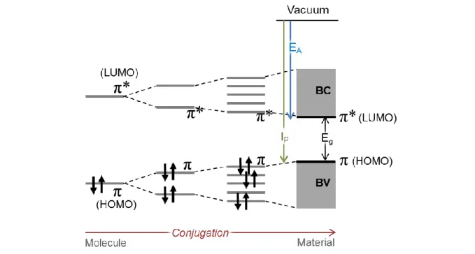
oxygen, sulfur). The conjugation of their π-atomic orbitals along the backbone, i.e. the alternation of single σ carbon bonds and π+σ double bonds, results in the formation of delocalized π molecular orbitals.
The frontier electronic levels (Highest Occupied Molecular Orbital, HOMO and Lowest Unoccupied Molecular Orbital, LUMO) determine the optical and electrical properties of the molecules. In a
technologies (single and multijunction cells based on CdTe, copper indium gallium selenium or CIGS, a-Si, micro-crystalline Si, …)
Fig. 12. Structure of polymeric (1 and 2) donor materials., 1: poly-(3-hexylthiophene) or P3HT, 2: Poly[N-9'-heptadecanyl-2,7-carbazole-alt-5,5-(4',7'-di-2-thienyl-2',1',3'-benzothiadiazole)] or PCDTBT, and of a molecular acceptor material, 3: [6,6]-phenyl C61-butyric acid methylester or PCBM or PC61BM.
20
molecule, the electrons can be ejected from the HOMO (characterized by the ionization potential Ip) or
captured by the LUMO (characterized by the electronic affinity EA). When the molecule lengthens, the
gap between the HOMO and LUMO levels decreases. If the length of the molecule increases indefinitely, the orbitals will be so close that they will form an energy band (Fig. 13). The ensemble of the π orbitals will form the valence band and the π* orbitals the conduction band. The HOMO and LUMO normally characterize an isolated molecule, but it is common to use them in the solid phase, the HOMO designating the top of the valence band and the LUMO the bottom of the conduction band. For organic semiconductors, the bandgap is defined as the difference between the HOMO and the LUMO.
1.2.4.2. Working principle and structure of an organic photovoltaic solar cell
The working mechanism of photon flux conversion into electrical energy can be divided in four steps (Fig. 14):
1) photon absorption 2) exciton diffusion 3) exciton dissociation
4) carrier transportation and collection.
Fig. 13. Energy diagram of the π molecular orbitals when the conjugation length increases (either by the lengthening of the polymer chain or by interactions between molecules).
21 Firstly, an incident photon, arriving on the organic semiconductor and having an energy that exceeds the semiconductor bandgap, excites an electron to an unoccupied state above the bandgap, creating an electron-hole (e-h) pair, called an exciton. Contrary to inorganic semiconductors, in which the exciton is weakly bound (~10 meV) and is dissociated spontaneously, the binding energy (Coulomb force) of the exciton in the organic semiconductor is much higher (~0.1-1 eV) than the thermal activation energy at room temperature (~25 meV), so that a thermal dissociation is not allowed.
Secondly, the exciton diffuses inside the material until it reaches a dissociation site or recombines. Ideally, the size of the organic domain in which the exciton diffuses should be equal or lower than the diffusion length of the exciton, which is around 10-20 nm in organic materials. Excitons are mainly diffusing because it is a neutral quasi-particle and is thus not affected by external fields.
The third step is exciton dissociation. In polymer solar cells, the electron-hole pair which was created through absorption is held together by coulombic forces. However, for the solar cell to generate electricity, the electron and hole must be separated, and subsequently collected at electrodes of opposite polarity. In order to accomplish this, the exciton bond must be broken. This is done by introducing a secondary organic semiconductor in the active layer, which has an energetically lower lying LUMO-level, such that electron transfer between the two types of semiconductor is favorable. The material with the highest LUMO is called the electron donor while the other is called the electron acceptor. The exciton binding energy must be lower than the difference between the LUMO level of
22
the donor and the LUMO level of the acceptor. In state-of-the-art polymer solar cells, the heterojunction is between a polymer donor (for example poly-(3-hexylthiophene, P3HT) and an molecular acceptor (for example the fullerene derivative [6,6]-phenyl-C61butyric acid methylester,
PCBM). Most of the excitons are actually generated in the donor phase because of the higher absorption in the polymer than in the fullerene, and electrons are transferred to the fullerene acceptor. During the fourth step, the charges then diffuse to the electrodes (the holes towards the anode in the donor and the electrons towards the cathode in the acceptor) and are injected in the electrodes, delivering a current and a voltage in the external circuit. Charge carrier mobility depends on how the frontier π orbitals overlap, and consequently on the morphology and crystallinity of the organic film. In the case of the bulk-heterojunction solar cells, the phase orientations are random. The current flow is controlled by the use of electrodes having sufficiently different work functions (the anode electrode is chosen with a high work function material and the cathode is selected with a low work function material, usually a metal).
Initially, the polymer (donor) and the fullerene (acceptor) were deposited in a bilayer configuration, similarly to inorganic semiconductors (p-n junction). But at the same time, the photons need to go through a certain thickness of active layer (100-200 nm) for the active layer to absorb most of them. Due to the small exciton diffusion length, the donor-acceptor layer was structured in a bulk heterojunction: a typical structure of organic solar cell (based on a polymer/fullerene bulk heterojunction) is shown in Fig. 15. The polymer donor (P3HT) and the fullerene acceptor (PCBM) form a 100-200 nm thick layer with separate domains of P3HT and PCBM. The layer is in-between two electrodes, typically a transparent one (indium tin oxide, ITO) and a metallic one (aluminum).
Bulk heterojunctions were made by mixing both materials together and depositing them together (usually by spin-coating at laboratory scale) to form interconnected domains large of a few tens of nm
Fig. 15. Schematic view of a typical organic solar cell in normal structure, with the corresponding structures of the materials. The light is absorbed in the P3HT:PCBM layer.
23 size, which form upon drying (and sometimes annealing).69 The resulting three-dimensional nanoscale
phase separation in the active layer increases the junction area and allows the formation of efficient solar cells.
In Fig. 15, a layer called a hole-extraction layer (HEL) and made of PEDOT:PSS (poly(3,4-ethylenedioxithiophene):poly(styrene sulfonate)) is used to improve the ITO-P3HT interface (smoothing of the ITO surface, improvement of charge collection in ITO).70 A wide variety of
materials (polymers and molecules) have been reported for the building of organic solar cells.71–73
1.2.4.3. PEC based on organic semiconductors
OSC have been used for solar water splitting devices in different configurations. In this part, a short review on significant devices is presented.
Photocathodes were built based on single OSCs such as polyacetylene, polyaniline, polypyrrole, poly-(3-methylthiophene) or poly-(3-hexylthiophene). These photoelectrodes were made in situ by electropolymerizing a monomer in solution onto a conductive electrode (for example ITO). Their photo-electrochemical behavior was studied and sometimes photo-electrosynthesizing properties were reported (hydrogen or other compounds). Only a few µA cm–2 photocurrent density were obtained in
aqueous environment74–78 and as demonstrated later, the photocurrents were not corresponding to
production of hydrogen.79
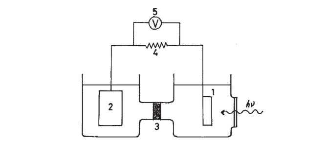
Meanwhile, heterojunctions of two different organic semiconductors started to be developed in electric solar cell configurations to improve the exciton dissociation within the organic layer (cf. previous subsection). The works on P3HT/electrolyte junctions described before resulted in photocurrents of a few tens of µA, showing that the presence of an electrolyte was not enough to help charge separation, and that an acceptor was necessary to improve charge separation. Thus, in 2012, Abe and coll. built an ITO\P3HT:PCBM BHJ photoelectrode.80 They did not use any interfacial layer between the ITO and
the BHJ, but an electron acceptor or donor was added in the electrolyte to tailor the direction of the charge collection. They expected that the collection of either electrons or holes at the BHJ/electrolyte interface would decide whether the photoelectrode would be a photocathode or a photoanode respectively. Surprisingly, only a photoanodic current could be obtained, in the presence of the donor, but no photocathodic current was obtained with the acceptor, though holes from the P3HT are usually well transferred to the ITO. The same year, a P3HT:PCBM BHJ on ITO was used without catalyst as H2-evolving photocathode in aqueous NaCl, Cl– being used as sacrificial donor.12 Tested in a two
electrode configuration (with a Pt counter electrode), a peak current density of 100 nA cm–2 was
reached. Stable photocurrents were obtained over 28 h, but the hydrogen bubbles were sticking to the surface.
To enhance proton reduction at the photocathode surface, a Pt catalyst was added at the top of an evaporated small-molecule (phthalocyanine/fullerene) p/n planar junction and generated 800 µA cm–2
24
photocurrent density corresponding to H2 evolution in aqueous phosphoric acid (pH = 2).81 It was
shown that the photophysical events within the bilayer (i.e., visible-light absorption, carrier generation at the p/n interface, conduction of electron and hole in each layer) were the same than in the corresponding solid-state photovoltaic cell. The difference lies in the fact that in a solid-state solar cell, the charge transfer at the organic semiconductor/metallic electrode interface is not limiting, while for the photoelectrode interfaced with an electrolyte, the rate-limiting charge transfer occurs at the solid/liquid interface (thus the presence of Pt). This work shows however that an organic bilayer that is usually a part of a solid-state photovoltaic cell can be turned into a photoelectrode in wet conditions.82
Based on their previous work, Abe and coll. built a full PEC device with a H2Pc/C60/Pt photocathode
and a perylene/H2Pc photoanode in the water phase (Fig. 16).83 Hydrogen was evolved from water but
the photoanode needed a sacrificial donor (a compound that is oxidized at a lower potential than water).
It is worth to note that a PV-biased electrosynthetic cell was reported in 2013 by Janssen and coll.84 It
consisted in an all-solution-processed triple junction polymer solar cell with an open-circuit potential (VOC) of 2.33 V, which was connected to an electrolyzer to perform water splitting (Fig. 17).
Fig. 16. Schematic illustration of the photocatalysis system of H2Pc/C60/Pt and PTCBI/H2Pc. PTCBI =
3,4,9,10-perylenetetracarboxylic-bis-benzimidazole. D = donor compound (thiol). Reproduced from Ref.83