HAL Id: hal-00926309
https://hal.archives-ouvertes.fr/hal-00926309
Submitted on 9 Jan 2014HAL is a multi-disciplinary open access archive for the deposit and dissemination of sci-entific research documents, whether they are pub-lished or not. The documents may come from teaching and research institutions in France or abroad, or from public or private research centers.
L’archive ouverte pluridisciplinaire HAL, est destinée au dépôt et à la diffusion de documents scientifiques de niveau recherche, publiés ou non, émanant des établissements d’enseignement et de recherche français ou étrangers, des laboratoires publics ou privés.
Proton exchange membrane fuel cell operation and
degradation in short-circuit
Rosa Elvira Silva, Fabien Harel, Samir Jemei, Raphaël Gouriveau, Daniel
Hissel, Loïc Boulon
To cite this version:
Rosa Elvira Silva, Fabien Harel, Samir Jemei, Raphaël Gouriveau, Daniel Hissel, et al.. Proton exchange membrane fuel cell operation and degradation in short-circuit. International Conference on Fundamentals and Development of Fuel Cells (FDFC 2013), Apr 2013, Germany. 6p. �hal-00926309�
PROTON EXCHANGE MEMBRANE FUEL CELL OPERATION
AND DEGRADATION IN SHORT-CIRCUIT
R.E. Silvaa, b, d, F. Harelb, S. Jemeia, b, R. Gouriveaua, b, c, D. Hissela, b, L. Boulond, K. Agbossoud
a FEMTO-ST Institute UMR CNRS 6174, University of Franche Comté, Techn’Hom 90010 Belfort, France
b FCLAB FR CNRS 3539, ,Techn’Hom 90010 Belfort, France
c
National Engineering Institute in Mechanics and Microtechnologies, 26 Rue de l’Épitaphe 25000 Besançon, France
d Institut de Recherche sur l’Hydrogène, Université du Québec à Trois-Rivières, Trois-Rivières, Canada G9A 5H7
Keywords: proton exchange membrane fuel cells, short circuit, degradation mechanism, electrochemical impedance spectroscopy.
ABSTRACT
This paper presents an experimental study dealing with operation and degradation during an electrical short circuit of a proton exchange membrane fuel cell stack. The physical quantities in the fuel cell (electrical voltage and current, gas stoichiometry, pressures, temperatures and gas humidity) are studied before, during and after the failure. After a short circuit occurs, a high peak of current appears but decreases to stabilize in a much lower value. The voltage drops in all the cells and even some cells presents reversal potentials. The degradation is quantified by using electrochemical impedance spectroscopy.
1. INTRODUCTION
The performance of a Proton Exchange Membrane Fuel Cell (PEMFC) is affected by many direct and indirect factors such as fuel cell design and assembly, material properties, operating conditions, and impurities or contaminants. In order to improve cell lifetime, it is important to identify and understand the potential failures and then analyze its mechanisms to allow mitigating their damage. The research presented in this paper is realized in the framework of a research project aiming to determine the influence on different failures in PEMFC operation. Among the operation modes, electrical short circuit represents a common and particularly undesirable failure in PEMFC [1], [2]. On the one hand, the risks of a long short circuit are a non-reversible degradation e.g. melting of the electrodes or at least an accelerated aging; on the other hand, some researches have demonstrated that under particular conditions, high current peaks for very short periods not only rise the temperature but also generate an excess of liquid water decreasing the membrane resistance and reducing the ohmic losses [2], [3]. Moreover, the performance of the fuel cell increases with the increase of the operating temperature [4].
Short circuits are generally originated by the penetration of conductive materials through the thickness of the membrane. The shorting objects may include the carbon fibers and binders of gas diffusion layers, aggregates in the catalyst layers [3]. Hard shorts can occur suddenly in an operating fuel cell stack where one cell develops a significantly higher ohmic resistance compared to the cells in the rest of the stack. As the stack continues to draw current from all cells, the cell with the abnormally high resistance can develop an excessive voltage drop and even reverse its cell potential [3].
The aim of this paper is to present an experimental study of the operation and degradation in PEMFC stack under electrical short circuit. A controlled short circuit is imposed between the electrodes of the fuel cell stack. Then the electrical and fluidic parameters are studied during and after this operation mode. An analysis of the degradation is realized by performing Electrochemical Impedance Spectrometry (EIS). This paper is organized as follows: Section 2 describes the fuel cell stack as well as explains the experimental setup. Section 3 presents experimental results. Section 4 presents the conclusions of this experimental research.
2. EXPERIMENTAL SETUP 2.1. Fuel cell stack and test bench
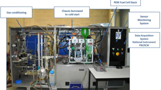
The fuel cell stack is fed with air and hydrogen. It is composed of 40 cells connected in series, with an active surface of 220cm2 each. The nominal current of the PEMFC is 110A, the nominal (electrical) power is 3.8kW and the nominal operating temperature is 80°C. Hydrogen and air stoichiometry rates are fixed to 1.5 and 2 respectively. The test bench illustrated in Figure 1 is used to evaluate the fuel cell in both dynamic and static states [5].
Figure 1. 5kW Fuel Cell test bench at FCLAB 2.2. Short-circuit procedure
The PEMFC electrodes are directly connected by using a controllable circuit breaker. The current is measured by using a Hall Effect sensor. Fuses are used as redundancy protection.
2.3. Measures
Electrical, thermal and fluidic parameters are measured before, during and after the controlled short-circuit. It allows understanding the physical phenomena occurring in the stack. The EIS is used to determine the dynamic behavior of the fuel cell [6], thus it is used to define reference conditions to quantify the degradation. EIS are performed before and after the short circuit by using the spectrometer designed by S. Wasterlain [7].
3. EXPERIMENTAL RESULTS
A short circuit is imposed between the two current outputs of the fuel cell stack. However, the objective is not to perform a destructive test, and then the duration of the short circuit is limited to avoid strong thermal stress which can degrade permanently the fuel cell. This section presents the experimental results obtained for a short circuit with duration of 10s.
3.1 Electrical behavior
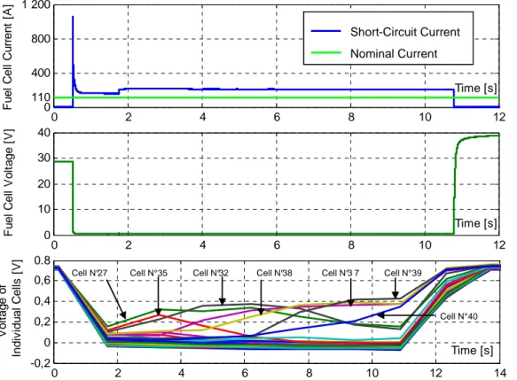
Figures 3a, and 3b illustrate the current and voltage during the short circuit. Figure 3c presents the voltage in each of the cells of the stack.
Figure 3a shows that the short circuit current (from 0.5 to 10.5 s) reaches a value of 1100A (5A/cm²) this represents near 10 times its nominal value. However, this current then decreases to stabilize at a value of near 2 times the nominal value. This is a relatively low value compared with electrical machines; here the current is limited by the mass transfer losses and by the hydrogen flow. This confirms the results presented by Hinaje et al. which use this phenomenon to use the fuel cell as a current source controlled on the hydrogen flow [8]. Figure 3b shows that the stack voltage drops near to 0V, even some cells presents reverse potential as illustrated in figure 3c and explained by [3] .This occurs mainly in the single cells that are far from the air input. The figure also shows that in some cells the voltage drops only about 50% of its nominal value, this is mostly the case in the single cells located near the air input.
(a)
(b)
(c)
Figure 3. PEMFC electrical behavior during short circuit
(a) current, (b) stack voltage, (c) individual cell voltage
0 2 4 6 8 10 12 0 110 400 800 1 200 Time [s] Fu e l C e ll C u rr e n t [A ] 0 2 4 6 8 10 12 0 10 20 30 40 Time [s] F u e l C e ll V o lt a g e [ V ] 0 2 4 6 8 10 12 14 -0,2 0 0,2 0,4 0,6 0.8 Time [s] V o lt a g e o f In d iv id u a l C e ll s [ V ]
Cell N°27 Cell N°35 Cell N°32 Cell N°38 Cell N°3 7 Cell N°39
Cell N°40 Short-Circuit Current Nominal Current
3.2 Thermal and fluidic behavior
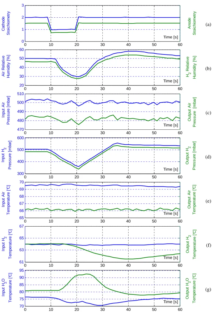
Figure 5 presents the experimental results for the gas stoichiometry, humidity and pressure, air temperature, H2 temperature and water (cooling) temperature. It is important to highlight that the
time scale is not the same than in Figure 3, this is because the fluidic time constants are much higher than the electrical ones; in the figure the short circuit is occurring from 9s to 19s.
During the short circuit the gas are consumed at a very high rate. The stoichiometric factors air/H2
decrease from 2/1.5 to 1/0.75 respectively. As the supply in gas is proportional to the current supplied to the load, water is produced at a very high rate. The excess of liquid water contributes to the reduction of the membrane resistance while reducing the ohmic losses in the membrane [2,8,9]. The high current, even during a short time, causes a rise in the stack temperature; the heat must thus be evacuated. This originates a high thermal gradient, the temperature (measured based on the cooling water temperature) rises to 92 °C; 15% higher than the nominal value.
3.3 Electrochemical Impedance Spectroscopy
Figure 4 presents the EIS (110A) results before and after the short circuit. Tables 1 and 2 summarize the polarization and ohmic resistance of the individual cells (in groups of 4). Experimental results exhibit that the change in the impedance spectra before and after a short circuit is not so pronounced, the value of the internal resistance of the stack increases by about 1.23% (passing from 17.24 to 17.03 mΩ). Similarly, for low frequencies, the polarization resistance of the stack evolves from 93.77 to 94.42 mΩ an increase of 0.69%. The value of the internal resistance of the stack has not really been an indicator of degradation after short-circuit. Nevertheless, the polarization resistance increases during short circuit on the low frequency capacitive arc associated with diffusion phenomena.
Figure 4. Electrochemical impedance spectroscopy before (nominal conditions) and after the short circuit Table 1. Ohmic and polarization resistances. Before Short-Circuit
Cell n° [5-8] [9-12] [13-16] [17-20] [21-24] [25-28] [29-32] [33-36] [37-40] Stack Rm [mΩ] 1.83 1.76 1.74 1.71 1.70 1.66 1.61 1.57 1.63 17.03
Rp [mΩ] 9.99 9.63 8.96 9.41 9.21 8.65 8.31 8.41 8.02 93.77
Table 2.Ohmic and polarization resistances. After Short-Circuit (10s)
Cell n° [5-8] [9-12] [13-16] [17-20] [21-24] [25-28] [29-32] [33-36] [37-40] Stack Rm [mΩ] 1.87 1.80 1.72 1.71 1.72 1.68 1.62 1.58 1.63 17.24 Rp [mΩ] 10.22 9.72 9.02 9.46 9.30 8.69 8.26 8.59 7.87 94.42 0 2 4 6 8 10 12 0 1 2 3
Impedance Spectra, Before Short-Circuit
Re(Z) [mOhms] -I m (Z ) [m O h m s ] 0 2 4 6 8 10 12 0 1 2 3
Impedance Spectra, After Short-Circuit
Re(Z) [mOhms] -I m (Z ) [m O h m s ] 0 20 40 60 80 100 120 0 10 20 30 Re(Z) [mOhms] -I m (Z ) [m O h m s
] Impedance Spectra, Stack
Before Short-Circuit After Short-Circuit
(a) (b) (c) (d) (e) (f) (g)
Figure 5. PEMFC fluidic behavior during short circuit
(a) Stoichiometry, (b) Gas humidity, (c,d) Air/H2 pressure, (e,f) Air/H2 temperature, (g) Water temperature
0 10 20 30 40 50 60 0 1 2 3 C a th o d e S to ic h io m e tr y Time [s] A n o d e S to ic h io m e tr y 0 10 20 30 40 50 60 20 30 40 50 60 A ir R e la ti v e H u m id it y [ % ] Time [s] H 2 R e la ti v e H u m id it y [ % ] 0 10 20 30 40 50 60 470 480 490 500 510 In p u t A ir P re s s u re [ m b a r] Time [s] O u tp u t A ir P re s s u re [m b a r] 0 10 20 30 40 50 60 300 400 500 600 In p u t H 2 P re s s u re [ m b a r] Time [s] O u tp u t H 2 P re s s u re [ m b a r] 0 10 20 30 40 50 60 65 66 67 68 69 70 In p u t A ir T e m p e ra tu re [ °C ] Time [s] O u tp u t A ir T e m p e ra tu re [ °C ] 0 10 20 30 40 50 60 61 63 65 67 In p u t H 2 T e m p e ra tu re [ °C ] Time [s] O u tp u t H 2 T e m p e ra tu re [ °C ] 0 10 20 30 40 50 60 70 75 80 85 90 95 In p u t H 2 O T e m p e ra tu re [ °C ] Time [s] O u tp u t H 2 O T e m p e ra tu re [ °C ]
4. CONCLUSIONS
This paper presents an experimental study about operation of a PEM fuel cell stack under electrical short circuit. After a short circuit occurs, a high peak of current appears (near 10 times nominal current) but decreases to stabilize in a much lower value (two times the nominal current), this is due to mass transfer losses limitation and the hydrogen flow as also concluded in [8]. The voltage in the cells varies and depends on the relative position regarding the gas input. The voltage drops in all the cells and even some cells present reversal potentials as presented in [3]. The temperature rises but the dynamic is much slower than the electric ones.
It is difficult to conclude the degradation by using EIS because the results before and after the short circuit are very similar. This could be because the short circuits were maintained for a relatively short duration. For further research, it could be interesting to study the effect of long duration short circuits.
REFERENCES
[1] Wang H., Li H., Yuan X., PEM Fuel Cell Failure Mode Analysis, PEM Fuel Cell Durability Handbook, 2011, Taylor & Francis Group.
[2] Fox C., Investigation of Shorting by Penetration in PEM Fuel Cell Membranes, 2009, Master’s
thesis, Virginia Polytechnic Institute and State University, USA.
[3] Mench M., Kumbur E.C., Veziroglu T. N., Polymer electrolyte fuel cell degradation, 2011, Academic Press.
[4] Tohidi M., Mansouri S., Amiri H., Effect of Primary Parameters on the Performance of PEM Fuel Cell, 2010, International Journal of Hydrogen Energy 35 9338 – 9348. The 1st Iranian Conference on Hydrogen amp; Fuel Cell.
[5] Candusso D., Harel F., De Bernardinis A., François X., Péra M.C., Hissel D., Schott P., Coquery
G., Kauffmann J.-M., Characterisation and modelling of a 5 kW PEMFC for transportation applications, 2006, International Journal of Hydrogen Energy 31 1019 – 1030.
[6] Springer T. E., Zawodzinski T.A., Wilson M.S., Gottesfeld S., Characterization of polymer electrolyte fuel cells using AC impedance spectroscopy, 1996, Journal of the Electrochemical Society, 143(2), 587-599.
[7] Wasterlain S., Candusso D., Harel F., François X., Hissel D., Development of test instruments and protocols for the diagnostic of fuel cell stacks, 2011, Journal of Power Sources vol. 196, n°12, Ed Elsevier, pp.5325-5333.
[8] Hinaje, M., Raël, S., Caron, J. P., and Davat, B. (2012). An innovating application of PEM fuel cell: Current source controlled by hydrogen supply. International Journal of Hydrogen Energy. [9] Wasterlain S., Candusso D., Hissel D., Harel F., Bergman P., Menard P., Anwar M., Study of
Temperature, Air Dew Point Temperature and Reactant Flow Effects on Proton Exchange Membrane Fuel Cell Performances Using Electrochemical Spectroscopy and Voltammetry Techniques, 2010, Journal of Power Sources 195 984 – 993.