Publisher’s version / Version de l'éditeur:
Vous avez des questions? Nous pouvons vous aider. Pour communiquer directement avec un auteur, consultez la
première page de la revue dans laquelle son article a été publié afin de trouver ses coordonnées. Si vous n’arrivez pas à les repérer, communiquez avec nous à [email protected].
Questions? Contact the NRC Publications Archive team at
[email protected]. If you wish to email the authors directly, please see the first page of the publication for their contact information.
https://publications-cnrc.canada.ca/fra/droits
L’accès à ce site Web et l’utilisation de son contenu sont assujettis aux conditions présentées dans le site LISEZ CES CONDITIONS ATTENTIVEMENT AVANT D’UTILISER CE SITE WEB.
Internal Report (National Research Council of Canada. Division of Building
Research), 1970-01-01
READ THESE TERMS AND CONDITIONS CAREFULLY BEFORE USING THIS WEBSITE.
https://nrc-publications.canada.ca/eng/copyright
NRC Publications Archive Record / Notice des Archives des publications du CNRC :
https://nrc-publications.canada.ca/eng/view/object/?id=2a06c01d-4650-4e11-8db6-773da9d943b6 https://publications-cnrc.canada.ca/fra/voir/objet/?id=2a06c01d-4650-4e11-8db6-773da9d943b6
Archives des publications du CNRC
For the publisher’s version, please access the DOI link below./ Pour consulter la version de l’éditeur, utilisez le lien DOI ci-dessous.
https://doi.org/10.4224/20337981
Access and use of this website and the material on it are subject to the Terms and Conditions set forth at
Edge temperature performance of sealed glazing units in cold weather
Sasaki, J. R.
DIVISION OF BUILDING RESEARCH
THE EDGE TEMPERATURE PERFORMANCE OF SEALED GLAZING UNITS IN COLD WEATHER
by J. R. Sasaki
ANAlYlfD
DBR Internal Report No. 371 of the
Division of Building Research
OTTAWA January 1970
GLAZING UNITS IN COLD WEATHER by
J. R. Sasaki
One problem as sociated with factory- sealed multiple -glazing units is thermal breakage of the inner pane. In cold weather the edge temperature of the inner pane is always lower than the temperature over the central portion because the thermal conductance of the edge spacer separating the pane s of glas s is higher than the air space conductance. This temperature difference produces a tensile stress along the edge of the inner pane. Breakage occurs when the tensile stre s s exceeds the edge strength of the glas s ,
The breakage potential of the inner pane is often increased when efforts are made to raise inside window surface temperature s to minimize condensation. High centre -pane temperatures occur when heater units are located beneath the window and discharge heated air against it. High centre -pane temperature s also occur in sealed units with a reflective metallic coating on one of the glass surfaces facing the air space. Although the metallic coating is intended primarily for reducing solar heat transmission, it also reduces the long wave
radiation transfer across the air space and raises inner pane tempera-tures.
The thermal-breakage potential of sealed units can be minimized by increasing the edge temperature of the inner pane.
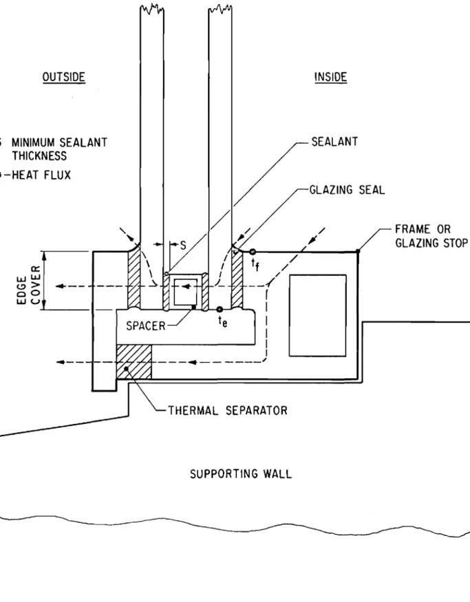
The factors affecting the edge temperature can be predicted from a simple heat balance between the sealed unit and the window frame, as illustrated in Figure 1. The edge temperature of the inner pane, t e , should increase if the following conditions are obtained:
(l) The thermal conductance of the inner glazing seal is high, relative to the conductance of the outer seal. (Conductance is directly proportional to the conductivity and the eros
s-sectional area of the heat flow path, and inversely proportional to the length of the heat flow path. );
(2) The outside edge cover is large, relative to the inside cover. This advantage will only be realized if the thermal conductance of the edge cover is relatively low;
(3) The thermal conductance of the edge spacer is low; and (4) The thickness. s , of sealant between the glass and spacer
is large.
The conductance of the glazing seals (condition 1) will have a favourable effect on the edge temperature only when the inside frame temperature, tf' adjacent to the sealed unit is high. This temperature will be high if the inner portion of the frame has a high thermal con-ductance and a large area exposed to the inside air, and if the outer
portion of the frame has a low conductance or contains a low-conductance thermal separator.
This report presents the results of tests performed in the DBR/NRC cold-room facility to determine how the foregoing factors affect the inside edge temperature of sealed multiple-glazing units. In the first series of tests, the surface temperature characteristics of 20 sealed units were investigated in a thermally neutral frame. This group included both idealized and proprietary units that differed in air space thickness, spacer conductance, sealant thickness, and edge protection.
In the second test series the effects of frame design, glazing detail. and heater configuration on the edge temperature of two sealed double -glazing units were inve stigated. One of the units was an ordinary clear unit; the other had a low-emissivity metallic coating on the
outer surface of the inner pane.
DESCRIPTION OF TEST APPARATUS
The tests were performed in the DBR/NRC cold-room facility with the te st units installed in the partition between the cold and warm rooms as shown in Figure 2.
The cold-room conditions remained unchanged for all tests. The cold-air temperature was controlled to -20°F. A multiple nozzle chamber was located in front of the cold side of the specimen to provide uniform surface conductance over the cold surface. The chamber was pressurized by a blower installed in the rear wall of the chamber. Flow re strictions and pre s sure equalization plenums within the chamber
provided a uniform air discharge from the 213 nozzles (2-in. inside diameter) installed in the front panel of the chamber. The nozzle outlets, located 4} in. from the glass surface, discharged air normal to the window surface. In order to minimize differences in the surface conductance value s in front of and between nozzle outlets. the front panel was slowly rotated in its own plane with the centre of each nozzle
describing a 3-in. diameter circle. The discharge rate was adjusted to provide a surface conductance value of approximately 4. 5 Btu/hr fta OF.
The air temperature on the warm side was :ontrolled to 72 of for all tests. The air flow over the warm face of the specimen was by either forced or natural convection. For the natural-convection tests, the air on the warm side was heated by the electric convector located at the base of the warm room wall facing the specimen. The mean surface conductance value over the specimen face was approximately 1.2 Btu/hr fta
°
F. The heater configurations providing forced-convection air flow on the warm side are described in the appropriate tests. A hot-water induction-air heater was located beneath the window for these tests.Surface temperatures were measured with copper-constantan thermocouples and an electronic temperature indicator. Ribbon-type thermocouples, 0.002 in. thick by
i
in. wide, were used on the glasssurfaces; 30 -gauge wires with twisted junctions were used on the metal surfaces. The thermocouples were attached to the surfaces with adhesive cement and tape.
The reference cold -air temperature, t c' was measured at the mid-height of the specimen
4t
in. from the cold face of the specimen. With natural-convection air flow on the warm side, the reference warm air temperature, t w' was measured at the mid-height of the specimen 6 in. from the inner specimen face. With forced convection onthe warm side, t w was measured 12 in. from the inner specimen face.The measured surface temperatures, t , were expressed as a temperature index defined as:
t - t
c
t - t w c
where t = measured surface temperature, of t = reference warm air temperature, of
w
t = reference cold air temperature, of c
The advantage of expressing the temperature characteristic of a window in terms of temperature index rather than temperature is that, for any particular configuration, the index is practically independent of test air temperatures over the temperature range of interest.
SERIES I EFFECT OF GLAZING-UNIT DESIGN ON EDGE TEMPERATURE
Test Configuration and Test Conditions
The units tested in this series are shown in Figure 3. The units were app r oxirnat eIy 14 in. wide by 20 in. high. Unit 20 was triple glazed while the r ern a.ining units were double glazed. All units with the exception of the idealized double units (1, 2, 3 and 11) were sealed.
Units 1 and 11 with the polystyrene spacers were intended to show the optirnum edge terripe r atur e pe rf'o r-m anc e obtainable with sealed double-glazing units. The units 2 and 3 were idealized att ernpt s at utilizing non-m e taIli c spacer rn at e r i.a.ls , Units 9, 12, 13 and 20 were de ve l oprrie nt.a l units, and the r erna irid e r were proprietary units currently on the rn a rket ,
The units were tested in a wooden f r am e , The m e thod of installing the units in the c o.Idv r oorn partition is shown in Figure 4a,
and the surface the rrrioc oup le locations are shown in Figure 4b. The tests were pe rEo rrn ed with forced-convection air flow and an air
terripe r atu r e of -20°F on the cold side; and with natural-convection air flow and an air temperature of 72°F on the warm side.
Test Results
The edge configurations and the surface terripe r atur e characteristics of the 20 units are listed in Tables I and II. The rn inirnurn ternpe r atu r e on the inner pane of the sealed units always occurred along the bott orn edge. The term, edge temperature, used in the following discussion refers to the rn i n irriurn edge terrrpe r atu r e of the inner pane.
Edge teITlperature perforITlance
The rn inirnurn edge terripe r atu.r e index of the units varied f r orn a high of 52 to a low of 33. The edge indices of the ideal units (1 and 11) were 52 and 51, respectively, reflecting the low t.he r m a.l conductivity of the polystyrene spacer (the rrnal conductivity, k セoN 3 Btu in./hr ft 2 OF). Unit 2, with the solid neoprene spacer (k セ 1), and unit 14, with the welded glass edge (k セ 6), both had an edge index of 43. Units 12 and 13, with a reinforced plastic spacer (k セ 2), had edge indices that were s irn.iIa r to those of the units with rnetaI spacers (k セ 115 to 1400). The edge t.ernpe r atu r e for the rnaj o ri.t y of the units, therefore, did not depend exclusively on the the rrn a l conductivity of the spacer.
The edge temperature of the i -in. units with metal spacer showed some dependance on the thickness of material between the metal spacer and the glass, as shown in Table III. The variation in edge index with sealant thickne s s was 4. The effect of sealant thickness on edge temperature was indeterminant for the i-in. units because of negligible sealant thickness in these units. The edge indices varied from 36 to 38 and were comparable to the indices of i-in. units with greater sealant thickness. Reduced convective heat transfer at the bottom of the narrow air space could explain the warmer glass edge.
The protective metal around the edge of the unit had some effect on edge temperature, as shown in Table IV. The edge index was increased by as much as 3 when the metal surround was removed from a unit.
The edge temperature performance of the triple -glazed unit was similar to that of the double -glazed units. The thermal resistance added at the edge by the extra glass thickness had, therefore, a
negligible effect on edge temperature.
Surface teITlperature profile and breakage potential
The inside surface temperature profiles of representative units are shown in Figure s 5 and 6. Figure 5a compare s the profile s of the three idealized セMゥョN units. Because the glass and air space thicknesses were identical, the profile s were identical over the centre region of the units and differed only near the edge. Two proprietary i-in. units with the highest and lowest edge temperatures are compared in Figure 5b. The profile s of the se units were nearly identical but were lower than the profile of the ideal unit 1.
The surface temperature profiles of the ideal i-in. unit, the
glass-weld unit, and a proprietary i-in. unit with a high edge temperature, are shown in Figure 6a. The figure indicate s the large variation in
profiles obtainable with units nominally having the same air space thickness. The profile variation is related to the glass and air space thicknesses. When a sealed unit is cooled, the panes of glass tend to deflect towards each other and reduce the air space thickness in the centre region. This reduction in air space thickness effects a local reduction in surface temperature that is greater for the narrow air space than for the large. Since thin glass deflects more readily than thick glass, a narrow sealed unit with thin glass tends to have lower
The profiles of typical i-in. and }-in. units are compared
with that of the triple -glazed unit in Figure 6b. The profile depre s sion at the centre of the triple -glazed unit was caused by deflection of the thin panes of glass.
The breakage potential of the inner pane can be represented by the difference between the mean pane index and the minimum glass -edge index. This breakage -potential index difference and the mean pane index are listed in Table I and II. The mean pane indices listed are not those of the particular units tested but represent the mean temperatures that would obtain on units with the air space thickne s se s shown and equal in size to the units tested in Series II. The breakage potentials given are, therefore, comparable with the results of Series II. The breakage-potential index difference of the ideal }-in. unit was 10; that of the remaining}-Ln , units varied from 19 to 29. The breakage -potential
index difference of the ideal i-in. unit was 6; that of the remaining double-glazed units varied from 12 to 23; that of the triple -double-glazed unit was 25. The breakage-potential index difference of the proprietary i-in. units was Les s than that of comparable}-Ln , units because the narrow units had lower centre -pane temperatures.
SERIES II - EFFECT OF FRAME DESIGN, GLAZING DETAIL, HEATER CONFIGURATION AND GLASS TYPE ON EDGE TEMPERATURE Test Units and Conditions
Two sealed double -glazing units were te sted with a number of frame and heater configurations. The design of the sealed units was
identical to that of unit 8 shown in Figure 3. The units were approximately 48 in. high by 39 in. wide and had a nominal air space thickne s s of tin. One unit consisted of two panes of clear glass and was designated the "c1e a rl/ unit. The other unit also had two clear panes but the inner pane had a thin aluminum coating on the surface facing the air space; this unit was designated the "r efl e cttve " unit. The thermal conductance of the air space in the reflective unit was approximately 57 per cent that of the clear unit.
The design details of the five frames tested are shown in Figures 7 to 11. Frame s A and B were of similar construction and consisted of inner and outer aluminum members held together by steel screws.
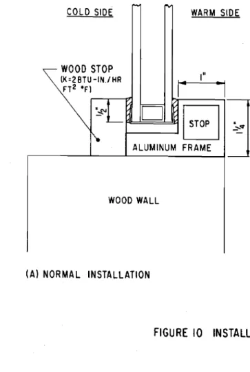
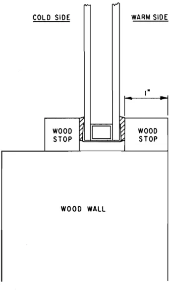
Frame C was also aluminum but had the thermal separation between warm and cold frame members outside of the outer glazing stop. Frame D was a combination of wood and aluminum having an inner member of aluminum and an outer glazing stop of wood. Frame E was made completely of wood.
All tests were performed with forced-convection air flow and an air ternpe r atu r e of -20 ° F on the cold side; and an air temperature of 72°F on the warm side. The warm-side air flow and heater conditions were varied for the different tests. Surface tern pe r atu r e s were measured on the sealed units at the locations shown in Figure 12. Frame tempera-tures were rn e a su r e d on the cold and warm side s adjacent to the edge of the sealed unit.
Test Configurations
The sealed units were tested with the configurations listed in Table V.
The glazing rnat e r i a.Is and glazing methods used in the te sts are shown in Figure 13. The "butyPI glazing seal represented seals having a relatively high thermal conductance. A thin (1/16-in.) neoprene face shim and sealant placed between the unit and the glazing stop had thermal properties s irrri.l a r to the "butyl" seal. The ribbed "vinyllt seal represented a seal having a relatively low thermal conductance. Its behavior was
similar to that of a ribbed or hollow compressible gasket made from neoprene.
The glazing designations are only relevant to metal frames, and refer to the thermal connection between the sealed unit and the warm side of the fr arn e , The glazing method with the low conductance seal on the cold side and the high conductance seal on the warm side would tend to raise the edge temperature of the inner pane and is, therefore, designated the "favourable" method.
The clear and reflective units were tested in Frame A (Figure 7) with both natural- and forced-convection air flow on the warm side. The glazing rn e th od and the frame area exposed to the wa rrri air were varied.
The r ernaining frames were tested with only the reflective unit. F'r am.e B (Figure 8) was tested with natural-convection air flow on the wa rrn side, and with the warm-side frame exposure and the glazing method varied.
F'r-arrie C (Figure 9) was tested with the air flow condition and the frame exposure on the warm side varied.
Frame D (Figure 10) was tested with natural-convection air flow on the warm side. An additional test was performed with the cold-side edge cover increased.
Frame E (Figure 11) was tested with natural-convection air flow on the warm side.
Test Results
The test results are listed in Tables V, VI and VII in terms of temperature indices.
The minimum inside glass-edge temperature occurred along the bottom edge of the inner pane for all configurations. The minimum edge index, the inside frame index, the mean inner -pane index, and the
breakage-potential index difference of the inner pane, .61 (mean-edge), are listed in Table V for all tests. The vertical surface te:mperature
profiles for a select number of tests are listed in Table VI. The minimum edge te:mperature indices and the breakage potentials for various test
configurations are compared in Table VII on the bases of glass type, glazing method, frame design, and warm-side heater and air flow conditions.
Glass type
The inside surface temperature profiles of the clear and reflective units in Frame A with identical glazing detail and air flow condition are compared in Figure 14. The rn e an pane index of the reflective unit was
higher than that of the clear unit by 10 due to the lower air space conductance of the reflective unit. The edge indices of the two units, however, were nearly identical as both had the same edge construction. The breakage-potential index difference of the reflective unit was from 11 to 15 greater than that of the clear unit for the same conditions of installation.
Glazing method
(a) Conductance of glazing material - The minimum edge temperatures of the clear and reflective units obtained with the unfavourable, neutral, and favourable glazing methods are compared in Table VII. The breakage -potential index difference with the favourable glazing method was from 13 to 17 les s than that with the unfavourable
method. The breakage potential of the reflective unit with favour-able glazing was approximately equal to that of the clear unit with unfavourable glazing.
(b) Edge cover - The test results obtained on Frame D with a wooden edge cover of } and 1 in. on the cold side are listed in Table VII.
Doubling the cove rage of the glas s edge by the oute r glazing stop reduced the breakage -potential index difference of the inner pane by 4. A similar effect would have resulted if the warm-side edge cover had been decreased.
Thermal characteristic of frame
The minimum edge temperatures of the reflective unit in the five frames are listed in Table VII. The glass -edge temperature
reflected the inside frame temperature in all tests with favourable glazing.
The inside frame temperatures of Frarres A and B were relatively high and increased with increasing frame exposure. The breakage-potential index difference s of 26 and 27 obtained with favourable glazing and frame exposures of 9 in. (Frame A) and 4 in. (Frame B) were comparable to that of the clear unit with a frame exposure of
3t
in. (Frame A) and neutral glazing.The frame and glass -edge temperatures of Frame C were much lower than those of Frame B even though both had the same inside frame exposure. The thermal separation in Frame C was apparently less than that provided by the steel screws in Frame B. The low inside frame temperature may also have resulted because heat was lost from the frame to the outer pane as well as to the inner pane.
The inner frame and glass-edge temperatures obtained with Frame D were relatively high because of the low thermal conductance of the outer frame member. The wooden frame section minimized the heat los s from the inner frame and from the edge of the sealed unit. The breakage -potential index difference of 26 obtained with a frame exposure of
2t
in. was comparable to those obtained in Frame s A and B with much larger frame exposures.Frame E had a low-conductance glazing stop on both side s of the sealed unit. The breakage -potential index difference of 40 was, therefore, similar to those obtained with neutral glazing in the aluminum frames, and was greater than that obtainable with favourable glazing in an aluminum frame.
Heater configuration and air flow condition
The minimum edge temperatures measured on the clear and reflective units with the natural- and forced-convection air flow and heater
con-figurations are compared in Table VII. The inside surface-temperature profiles for these tests are shown in Figure 15.
The forced-convection tests were performed with an under-window heater. The heater outlet was located 7 in. from the inner pane and 8セ in. below the sill for Frame A; and 4 in. from the inner pane and at sill level for Frame C. The heater discharged air towards the window with a velocity of approximately 300 ft/min. The tempera-ture index of the discharged air was higher than the reference
warm-side air temperature and was approximately 110.
The under-window heater configuration for Frame A was such that the heated air flow impinged against the inner pane near mid -he ight ,
The centre -pane temperatures were, therefore, raised more than the temperatures near the sill, and the breakage-potential index difference with forced convection was greater by approximately 6 than that with natural convection.
The under-window heater for Frame C was adjacent to the window sill and provided forced-convection air flow over the sill frame member as well as the whole inner pane. The minimum glas s -edge temperature and the mean pane temperature were, therefore, raised by the same amount, and the breakage potential with forced convection was the same as that with natural convection.
SUMMARY
The effects of various factor s on the breakage potential of sealed double-glazing units were investigated. The breakage potential of the inner pane of glass is a function of the mean pane temperature and the minimum glass-edge temperature which occurred along the bottom edge of the unit for all te st configurations.
(1) Glass type and air space thickness - Glass type and air space thickness affected only the mean pane temperature. The mean pane index of the reflective unit was approximately lO greater than that of the clear unit. The mean pane index of the セ -Ln , units was approximately 5 greater than that of the i-in. units. With natural-convection air flow on the warm side, the mean pane indices determined by test were 62 for the セMゥョN clear
units, 57 for the i-in. clear units, and 72 for the セMゥョN reflective units. The corresponding index for the i-in. reflective unit would be approximately 67.
(2) Glazing-l).nit design - The edge configuration of the sealed units affected only the minimum glas s -edge temperature. Sealed double-glazing units, as currently designed with metal spacers, had rnirrirnurn
edge temperature indices that varied from 33 to 39 when tested in a thermally neutral frame. In general, the units with a
protective metal surround had slightly colder edges than similar units without the surround.
A sealed unit de signed with a non -metallic spacer and without a metal surround would have a minimum edge index of between
40 and 43. There appears to be no practical method for fabricating a sealed unit with an edge index approaching the optimum value of
51.
(3) Frame design and glazing method - A sealed unit glazed in a neutral or low-conductivity frame such as wood was thermally independent of the frame. The glass -edge temperature of a unit glazed in a metal frame, however, was affected by the inside and outside frame tempera-tures and the glazing method. With the neutral glazing method, edge temperature was independent of frame temperature. With unfavourable glazing, edge temperature was independent of the warm-side frame temperature but dependent on the cold-side frame temperature.
Conversely, with favourable glazing, edge temperature depended only on the inner frame temperature. The minimum edge index with
unfavourable glazing was 7 to 11 les s than with neutral glazing; the index with favourable glazing was 6 to 8 greater than with neutral glazing.
The geometry of the glazing rabbet affected edge temperature, provided the thermal conductance of the cold-side edge cover was relatively low; when the cold- side edge cover was increased from} to 1 in. , the edge index increased by 4.
(4) Heater configuration and air flow condition - The under-window forced-convection heater arrangement provided higher inside surface temperatures than the remote natural-convection heater arrangement. The pattern of the increase in surface temperature depended on the heater discharge configuration and on the glazing method. When the heater discharged uniformly against the sill and centre -pane regions of a unit glazed favourably in a metal frame, both the mean pane and minimum temperatures increased equally. The breakage potential with these conditions was not increased appreciably. The breakage potential, however, would have increased if the unit had been in a neutral frame, or in a metal frame with neutral or unfavourable glazing. The breakage potential increased, regardless of the frame or the glazing method, when the heater discharged against the centre region of the inner pane only.
(SERIES I)
Nominal Air Space 1/2 -Ln, Double Glazing
UNIT (1) (Ideal) (2)(Idealized) (3)(Idealized) (4) (5) (6) (7) (8) (9) ( 10)
SPACER Polystyrene Neoprene Neoprene (1) II< St. Steel St. Steel Lead Lead Steel Aluminum Aluminum (Conductivity, (0.3) (1) Aluminum ( 115) ( 115) (240) (240) (300) (1400) (1400)
Btu-in.jhr fta eF) ( 1400)
CAP MATERIAL None None
I None ISt. Steel St. Steel None Lead tape St. Steel None Aluminum
I
I
Cap on Cap off
I Cap on Cap off
Top edge
*
I 68 HRVIJGセ 59 (39) 54 (34)-
- 48 (42) 45 (40) 46 (40) 50 (40) -Top sightline (TS) 70 (20) 63 (32) 58 (28) 47 (25) 53 (30) 57 (28) 50 (30) 51 (30) 55 (31) 47 (30) I I 4 3/4in. below TS 68 (10) 67 (11 ) 67 ( 10) 65 (10) 65 ( 9) 66 (10) 68 (10) 64 (10) 65 (10) 66 (10) iMid -height 65 ( 10) 65 (11) 65 (11 ) 61 (12) 64 (12) 65 (11 ) 64 (11) 63 (12) 64 (11 ) 64 (11) 4 3/4in. above BS 64 ( 9) 63 (11 ) 63 (11 ) 61 (10) 63 (11 ) 63 ( 9) 63 ( 9) 63 (11) 63 (11 ) 63 ( 10) 2 in. above BS 58 58 56 58 58 58 58 57 57 57 58 58 1 in. above BS 55 ( 8) 51 ( 9) 50 ( 9) 52 (11 ) 52 ( 9) 52 ( 9) 51 ( 9) 52 (10) 50 ( 8) 50 ( 9) 52 ( 9) 52 ( 91 1 in. above BS i 52 49 47 45 47 48 47 46 43 44 46 45 :;: i Bottom sightline (BS)' 51 (11 ) 46 ( 17) 42 (20) 40 (21) 40 (21 ) 42 (20) 42 ( 19 39 (22) 37 (21 ) 39 (22) 42 (20) 38 (25) Bottom edge 52 (17) 43 (24) 39 (26) 37 (30) 37 (30) 39 (30) 35 (30 35 (33) 33 (29) 36 (30) 39 (30) 35 (33) Inner Pane I (Mean) 62-'" I (Mean-Edge) 10 19 23 25 25 23 27 27 29 26 23 27*
Clear Glass Height 19in.**
Cold-side Indices in Bracket.VERTICAL TEMPERATURE - INDEX PROFILE OF INNER PANE -- UNITS II TO 20 (SERIES1)
Normnal Air Space 1/4 in. (Double) 3/8 in. (Double) 3/ I 6 in. (Double) 1/4-in. Double Glazing 3/16 in. (Triple) UNIT (11) (Ideal) (12) (13) (14) ( 15)
I
(16) (17) (18) ( 19) (20) SPACER Polystyrene Reinforced Reinforced Plastic Glass (Welded) Lead Steel Alurninurn Alurn inum Alurninurn St. Steel (Conductivity, (0.3) Plastic (2) (2) (6) (240) I (300) (1400) (115)Btu-in./hr fta0F) I
1 !
CAP MATERIAL None None St. Steel None None i None Alurn i.nurn None Steel St. Steel
I Cap on Cap off Cap on Cap off Cap on Cap off I
Top ・、ァ・Gセ 59 (29)':'* 47 (34) 44 (40) - - 44 (41) - I
i
!52
Top sightline (TS) 61 (24) I (22) 51 (27) 48 (31) 48 (32) 50 (28) 49 (31 ) I
4 3/4 in. below TS 63 ( 12) 62 (13) 65 (II) 58 (14) 58 ( 12) 59 ( 11) 60 (12) 60 (12) 62 ( 13) 66 ( 10)
t !Mid-height 61 ( 12) 60 (14) 62 (13) 54 (16) 56 (13) 57 (12) I 57 ( 13) 57 ( 12) 60 61 (11) 4 3/4 in. above BS 61 (14) 59 ( 15) 62 ( 13) 53 ( 13) 56 (14) 57 (12) 56 (12) 56 ( 12) 59 (15) 59 (15) 61 (10) I 56 55 61 I 2 in. above BS 58 51 54 55 I
I in. above BS 55 (12) 53 (11 ) 54 (10) 54 (10) 51 (15) 51 (II) 53 (11) 51 (11) 53 (12) 53 (13) 53 ( 13) 58 ( 8) 59 ( 8)
1 in. above BS 53 47 49 48 47 48 53 54 2" Bottom s ig htlin e (BS) 52 (17) 46 ( 19) 43 (19) 45 (19) 46 (23) 43 (22) 40 (22) 40 41 (22) 42 (23) 43 (23) 42 (23) 43 (24) :SOttOrrl edge 51 (23) 39 (25) 37 (29) 40 (29) 43 (29) 37 (34) 36 (31 ) 36 (34) 38 (34) 37 (33) 38 (33) 37 (33) 38 (35) ! nner Pane 1 (Mean)
- -
57- -
-r:-
55 57- -
62 -61 (Mean-Edge) 6I
18 23 12 20 21 21 19 20 19 25I
24EDGE TEMPERATURE PERFORMANCE - SEALANT THICKNESS (SERIES I)
do-in. Units)
Sealant Inside Glass Spacer
Thickness Edge Index Material Unit
S (in. ) IE With 0.025 37 St. Steel 5 Protective 0.005 37 St. Steel 4 Surround 0.005 35 Aluminum 10 < 0.002 33 Steel 8 With No 0.125 39 Aluminum 3 Surround 0.025 39 St. Steel 5 0.020 39 Aluminum 9 <0.002 36 Steel 8 < 0.002 35 Lead 7 0 35 Lead 6
EDGE TEMPERATURE PERFORMANCE - PROTECTIVE SURROUND (SERIES I)
Unit Spacer With With No Difference
Material Surround Surround
5 St. Steel
37
39
28
Steel33
36
3
13
Plastic37
403
19
Aluminum37
38
1
INSIDE GLASS - EDGE TEMPERATURE PERFORMANCE AT SILL (INDICES) (SERIES II)
WS =Warm Side Natural - Convection Forced - Convection CS =Cold Side Air Flow Air Flow
I I I 6I I I I 61
Test (Mean) (Edge) (Frame) (Mean- Test (Mean) (Edge) (Frame)
(Mean-Edge) Edge)
FRAME A (1) Clear Unit
Unfavourable glazing - WS exposure =3}u lAl 62 25 50 37 A2 70 27 54 43 Neutral glazing - WS exposure =
3t
ltlA3 62 35 58 27 A4 70 38 61 32 Favourable glazing - WS exposure =
3!"
A5 62 42 53 20 A6 70 44 56 26 - WS exposure =9 A7 62 48 61 14 A8 70 53 67 17 (2) Reflective UnitNeutral glazing - WS exposure =Sセョ A9 72 31 52 41 AIO 80 33 56 47 Favourable glazing - WS exposure =3-!-" All 72 41 52 31 AI2 80 42 54 38 - WS exposure =9" AI3 72 47 60 25 AI4 80 51 64 29 FRAME B (Reflective Unit)
Unfavourable glazing - WS exposure =
zt"
BI 72 26 46 46 Neutral glazing-
WS exposure=21"
B2 72 33 48 39 Favourable glazing - WS exposure =zl"B3 72 39 46 33- WS exposure =4" B4 72 45 53 27 FRAME C (Reflective Unit)
Favourable glazing - WS exposure .::: 21-" Cl 72 35 38 37
-
WS exposure =4" C2 72 39 42 33 C3 83 50 55 33 FRAME D (Reflective Unit, Favourable GlazCS edge cover =1... ing) Dl 72 46 56 26
l
CS edge cover =I" D2 72 50 59 22 FRAME E (Reflective Unit)
SURFACE TEMPERATURE INDICES ALONG VERTICAL CENTRELINE (SERIES il)
H = Clear Glass Height .. 48 in. WS = Warm Side
b" 13/4 H TestIBelow top
sightline 1/2H 1/4H b" Above bottom sightline 3" Above bottom sightline 2" Above bottom sightline 1" Above bottom sightline 111 z Above bottom sightline Bottom sightline
Bottom Frame Mean glass (sill) pane edge indices 53 (8) 62 (9) 5b(8) 70 (11) FRAME A Favourable glazing WS exposure = 3t" FRAME B Clear Unit
- Natural conve c ti on] A5 - Forced convectionIIAb
Rene cti ve Unit
- Natural convectionll All - Forced convectionIIA12 b5 (9t 74 (11) 75 (5) 83(b) b5 (10) 74 (12) 7b (b) 84 (7) b3 (9)
!
b3 (10) sa(8)I
7b (12)j70 (11) ss(9) I74
(b) 1 74 (6) 1 7 3 (b) 88(7) 83 (7) 80 (b) 58 (8) bl (9) b9 (5) 12 (5) 52 (8) 59 (9) sz(4) bb (5) 50 (8) 53 (9) 57 (4) 59 (5) 47 (lb) 50 (lb) 50 (8) 53 (8) 48 (28) 49 (29) 47 (23) 48 (22) I I42 (37) 44 (38) 41 (3b) 42 (37) 52 (9) 54(8) I 12 (b) 80 (7) Reflective unit Favourable glazing WS exposure = 4" FRAME C - Natural convectionll B4 75 (b)174
(7) 73 (7)1
7 3 (7)In
(b) b9 (b) ss(5) 58 (5) 52 (lO) 49 (23) 45 (39) 53 (13)I 72 (7) Reflective unit Favourable glazing WS exposure =4" FR.AM:E D - Natural convectionll C 2 - Forced convectionIIC3 81 (7) 82(7) 73 (b) 17 3(7)[72
(b) 85 (7) 91 (9) 19 5 (9) b8 (5) I i 83(8) sz(5) 79 (7) 5b (5) b9 (7) 49 (II) bl (15) 42 (28) 54 (37) 39 (37) 42 HZセXI 50 (48) 55 (50) 12 (7) 83 (8) Reflective unit Favourable glazing WS exposure =2" FR.AM:E E - Natural convectionll D 1 75 (b) 74 (7) 73 (7) 17 3(7)In
(b) b8 (b) b3 (5) I59(b) 53 (10) 49 (29) 4b (4l) 5b 12 (7) Reflective unitNeutral frame - Natural convectionll El 75 (b) 74 (b) 73 (b) 17 3(7) \12 (b) b8 (5) bl (5) 5b (5) 47 (8) 38 (19) 32 (28) 138 (26)
In
(6)FACTORS AFFECTING INSIDE GLASS - EDGE TEMPERATURE INDICES (SERIES II)
NC =Natural Convection; WS =Warm Side I 6 I 6 M 6
Test
FC =Forced Convection; CS =Cold Side (Edge) (Frame) (Mean-Edge) (1 ) Glass Type - Frame A (NC on WS)
Favourable glazing
-
Clear unit A5 421 53 1 20 11
-
Silver unit All 41 52 31(2) Glazing Method
(a) Relative Thermal Conductances of Glazing Seals. (NC on WS)
Frame A - Clear unit - Unfavourable Al 25 50 37
}
(WS exposure =3t") - Neutral A3 35 I 17 58 27 17 - Favourable A5 42 J 53 20
Frame A - Reflective unit - Neutral A9 31
10 52 41 10
(WS exposure =3t") - Favourable All 41 52 31 Frame B - Reflective unit - Unfavourable B1 26 46 46
(WS exposure =RセQャI - Neutral B2 33
}
13 48 39f
13 - Favourable B3 39 46 33(b) Depth of CS Edge Cover
F . = . D - Refle cttve urrit } CS edg e c ove r
- NC on WS =til D1 46
4 56 26 4
- Favourable glazing
=
1" D2 50 59 22 - WS edge cover=til(3) Thermal Characteristic of Frame
(Reflective unit; NC on WS; favourable glazing)
Frame A - WS exposure = 3 til All 41
6 52 8 31 6
- WS exposure
=
9" A13 47 60 25 Frame B - WS exposure =zilt
B3 396 46 7 33 6
- WS exposure = 4" B4 45 53 27 Frame C - WS exposure =
Z!tI
Cl 354 3'8 4 37 4
- WS exposure
=
4" C2 39 42 33 Frame D - WS exposure=
ziti
Dl 46 56 26Frame E E1 32 38 40
(4) Heater Configuration & WS Air Flow Condition
F r a=nA - C1e a r urrit }
- Favourable glazing NC A5 42
2 53 3 20 6
- WS exposure =3t" FC A6 44 56 26 - WS recess
=
7"Frame A - Reflective unit
}
NC All 411 52 2 31 7
(As above) FC A12 42 54 38
Frame C - Reflective unit
}
_ WS exposure =4" NC C2 39
11 42 13 33
FRAME OR
GLAZING STOP
SEALANT
GLAZING SEAL
THERMAL SEPARATOR
SPACER
tf
/ /
/....----,
- - /
(I
I
I
I
I ¥ -...イKMセ⦅MMM . . - -- - - - "S MINIMUM SEALANT
THICKNESS
-4-HEAT FLUX
SUPPORTING WALL
セ "., MAIN REFRIGERATING
MM]セ
UNIT ---<,-セセI
MULTIPLE NOZZLE BAFFLE CHAMBER , / AUXILIARY REFRIGERATING UNITCOLO ROOM WARM ROOM
14'- 4" I 15' - I" 7'-4" I 15'-1"
I
DOORI
DOOR PLAN VIEW MAIN REFRIGERATING UNITMULTIPLE NOZ ZLE CHAMBER BAFFLE PARTITION TEST SPECIMEN INLET CEILING HEIGHT - 10'-0"
--VERTICAL SECTIONFIGURE
2
COLD ROOM FACILITY
BASEBOARD CONVECTOR
S1. STEEL S1. STEEL __ (115) S1. STEEL 022'1
n
0-4S[
TGセcjャlj
I/a'.J
L
ALUMINUM (400) NEOPRENE, (I) \CD
NEOPRENE\ 0) \...
"..
.
'....
...
FOAM \ POLYSTYRENE \ (03) ALUMINUM I;."n
PS S=0020 ALUMINUM, (1400) PIB®
I-0'15'1n
S<0002 STEEL\ (300) \ LEAD TAPE LEAD (240) 51 -009''--1r1
®
FOAM セ POLYSTYRENE (0·3) \ セMc"
Jla
..
••••
REINFORCED TUBULAR PLASTIC-r-v (2) 0040-[ PIB@
REINFORCED@
PLASTIC, (2)®
WELDED GLASS (6) LEAD (240) SOLDER 0-44'[ STEEL ALUMINUM, PSs=o
91 "0111
n
PIB ALUMINUM ALUMINUM, (400)®
STEEL, (300) \S = MINIMUM SEALANT THICKNESS PIB= POLYISOBUTYLENE SEALANT
PS=POLYSULPHIDE SEALANT
FIGURE 3 DESIGN DETAILS OF SEALED UNITS - SERIES I
TOP r - - . -SfGHTLINE "...
....
v (/) W ::J: U Z C1'> - - - - -(3/4Hl セ :-20°F セ <.:> fo : 4·5 セ (FORCED CONVECTION) (/) (/) « ...J <.:> cr « w ...J UWOOD GLAZING STOP
WARM SIDE - - - - -(I/zHl - - - - ( 1 / 4 H l
セ
...--.l
セ
BOT TO_M - (0) - SIGHTLINE セ J".
,;:;' v-r
セ.0..
"... セ COL WARM SIDE tw : 72 OF fj : 1·2 Btu/hr ftZOF (NATURAL CONVECTION)セn
jセセセセイrene
GLAZING __ B_OTTOM ... SIGHTLINE WOOD PARTITION II ::J: COLD SIDE(A) INSTALLATION DETAIL - VERTICAL SECTION (B) THERMOCOUPLE LOCATIONS ON VERTICAL
t
70
(Bl UNITS 1,869
--e·- UNIT 1- NO CAP (IDEAL)
- e - UNIT 8- WITH CAP - 0 - UNIT 9- NO CAP 30
1
I,
,
,
,
I,
I., I
,
,
,
,
,
,
,
,
,
-
,
I I I I I I I,
1
eII
e#
N⦅セ・セ _ _ _ _-=-=-.:....:...:""-i--=S.:..::IG.:..::HT.:..::l::.c.IN=E'----,NM、BセM..(
--1e"
0/ '. Sセh l&J ... UNIT I z ::::; - e - UNIT 2 l-X - 0 - UNIT 3 !:! tJ'I :::E a I-I'2H I-0 <Xl l&J > a <Xl «(AI IDEALIZED UNITS 1,263
l-x (NO CAPS) c> W x 1/4 H 3" 2"
,"
0 BOTTOM EDGE IH=CLEAR GLASS HEIGHT=191N.
FIGURE 5 TEMPERATURE -INDEX PROFILES OF INNER
• 0
•
I
(B) UNITS 9,18a
20 ( '/2,1/4
8 TRIPLE) I" --.-- UNIT 9 (121 - . - UNIT 18 (1/4) - 0 - UNIT 20 (TRIPLE) I 70 60 • 0 50 40 (Al UNITS 11,14a
18 ( 1/4)
3D --... UNIT II (IDEAL) - . - UNIT 14(GLASS WELD)- 0 - UNIT 18
i
f
I • 0 ••J
1./
L/'
セッvQ
BOTTOM OMMMMMMッNNNNNNNNN[ZMNMMMMセM]セ」NNZNNNZZNK]N」ZNZNNZNNZN]]MMMNNNZセM」ZMMMMMMMM⦅⦅ャ 0 / . / ,0",
HiMMMMMMセ 0 . - -セMNセMiMMMMMMMセ \セャ
• 0 • I I I,
,
3/4 H....
z :::; セ :I: !,2 (/) :IE 0 セ 1/2 H セ 0 CD....
> 0 CD <l セ :I: !,2....
:I: 1/ 4H 3" 2" I" 0 EDGEH=CLEAR GLASS HEIGHT=191N.
FIGURE 6 TEMPERATURE -INDEX PROFILES OF INNER PANE_1/
4
,
COLO SlOE
\
( A) NATURAL-CONVECTION AIR FLOW
(BASEBOARD HEATER ONLY) WARM SIDE
,.
セ
l u m i nu m STOP I"r'
o
7" 3" c : - -l
MM]セヲ]]]] ALUMINUM STOPa
FRAMEセ
H c I ADDED FRAME EXPOSURE (ALUMINUM)
F===
•
Gセ
-
Nセセセ
0·'6" D1A.sセeel
SCREWS" 8" CENTRESWOOD WALL
J
3,-4
N
-
a->I"
,-
-I
...---...l.l:::p
I
Nセ{
0-14' DIA. STEEL L-..- SCREWS,S"CENTRES WOOD WALL COLD SIDE ALUMINUM STOP..
NWARM SIDE COLD SIDE WARM SIDE
3"
iセ
-I
セ
0
セII':ALUMINUM STOP
a
FRAMEセ
d
I
...
WOOD WALL
]
(A) WARM - SIDE FRAME EXPOSURE: 21
'4
(BI
WARM -SIDE FRAME EXPOSURE: 4"' ; , 300 FTIMIN.
\ ' \ \ ' \ \ \ r;=L====iltl
OUTLET 2"1( 30"
ED-CONVECTION AIR FLOW ER-WINDOW HEATER ONLY)
COLD SIDE WARM SIDE
I-
3"·1
-セAセ
セ
n
J
ii'
ALUMINUM STOP 8 FRAME
\\
セ
=0
I
セ
3 •'4 -WARM SIDE I"I-
"I
セdiNセ
ALUMINUM STOP 8 FRAME -, ,LpLASTIC THERMAL SEPARATOR
/
J.J
セセneopreneOセG
r
GASKET COLD SIDEI- . "I
セ
iiJ
N \'NUMiセover
セセi
<1R
セ
.___
1_ (JIセゥゥM
WOOD WALLIA) FRAME EXPOSURE : RQOセ IB} FRAME EXPOSURE: 4·
WOOD WALL WOOD STOP (K=2BTU -IN.! HR n2 "F) I"
セb
ALUMINUM FRAME WARM SI COLD SIDE 0::::[
\.l,J="8
n
iセ
STOP "- WOODSTOP ALUMINUM FRAME
WOOD WALL
DE
(AI NORMAL INSTALLATION lBl MODIFIED INSTALLATION
COLD SIDE WARM SIDE I"
·1
iセ
,/ WOOD :AD
セ
WOOD STOP1
STOP WOOD WALL=co セ c.o セ r-v' WOODEN
PARi'TTf
VERTICAL CENTRELINE " :x: " to-:x: C) W :x: IJ) IJ) oct -J C) Q: oct W -J UL
セセ
- - - ( 1 /2H) ---(1/4H) =c.o - - - (0) BOTTOM SIGHTLINE"--NLtUDL.
FRAME MMセ SILL DETAIL - - - - 3 - - - - 2 - - - - 1/2 BOTTOM SIGHTLINERIBBED VINYL STRIP
1/
2
EDGE COVER
_-T""""
TAPERED BUTYL
TAPE
THERMAL CONDUCTANCE
IBUTYL> VINYL
(A) GLAZING DETAILS
YL
WARM
COLD
SIDE
SIDE
NYL
BUT
セ
VI
YL
WARM
COLD
SIDE
SIDE
NYL
VIN
セセ
セVI
YL
WARM
COLD
SIDE
SIDE
TYL
VIN
セ
'/.BU
UNFAVOURABLE
NEUTRAL
FAVOURABLE
(B) GLAZING METHODS
H I - - - l
FRAME A
FAVOURABLE GLAZING METHOD
NATURAL-CONVECTION AIR FLOW
80
-
.-.
-\
70
60
•
I
I
I
I
II
-,,
,
CLEAR / REFLECTIVE
UNIT
!
UNIT
I
-
I
.-I
I
I
I
I
I
I
-
.-(62) (721.
-I
J
-50
2"
I--4
11I--6
11I--
42'r-=003'4H
I -oo::t"..
UJ Z - l I-::I: セ en :E oI-6
セ
H
l -cc 2 UJ>
o
co
<t I-::I: セ UJ ::I: . / . /.
",'"
Nセ,,""
.".-o
::-:. --.
BOTTOM
EDGE
I I-I
.-e:
----=: : -_I_
-1IGHTLlNf
framセo
40
セNM__
...L.._ _" " " _ - - - 'I
FIGURE 14 VERTICAL TEMPERATURE -INDEX PROFILES
OF INNER PANE - GLASS TYPE
100
\
•
90 FORCED CONVECTION•
•
•
\
80 70 60 UNDER-WINDOW FORCED -CONVECTION HEATER (B) FRAME C セセsideセセ
OJ
2" 4" 6" 42" 1/4H•
,
,
I I I•
r,
I I I I I NATURAL I CONVECTIONI I•
I I I I I I I I I•
I I I(72)MEAN1',
, / IIMEAN/· / . 1 I 183)o
_ . . . '
EDGEエSセNMM⦅NMMBGM
--!-X",--·
FRA .'ONMセN⦅MM⦅N⦅MMMMMMM
ME " . ' 30 40• 50I...• I I ! !- - }=:1
REFLECTIVE UNIT " w z ::J l -I <.:> Vl ::;: o l -t; I/ZH CD we;
CD <l: l -I <.:> W I 3/4H Co <;1" 90•
\
80 I I I I I I II
•
70 REFLECTIVE UNIT•
,
I I I I•
I I I,
I I,
NATURAL : FORCED CONVECTION, CONVECTION•
•
60セ
G
WARM " SIDE 3BBerZGGGセoG
i \
Gセ
FORCED-CONVECTI0][J\\\\ HEATER(Al FRAME A (FAVOURABLE GLAZING)
FORCED CONVECTION
•
•
•
CLEAR UNIT•
I
I I I I•
I
I I,
I,
NATURAL : CONVECTION IMEAN1' / ••" , • 1621:• • 1701 IMEAN1'I / / / 1131 I/. .
/I
.".
/セ
G
• I.
..,
.
'
' -.
'
'....:;>
⦅セ
I _ • __セ[Wᄋ
セN
L
IMEAN • • IONセセG
1801 50 60 70 80! 40iᄋセセ
セ
50- . . I I Ij
1/4 H 42" 4" 6" 2" UJ Z - l f-I <.:> V> :::;: o セ II H o Z CD UJ > o CD <l: f-I <.:> UJ Io
EDGE FRAME 40 _ 3/4H -ex:> <;1" I IFIGURE 15 VERTICAL TEMPERATURE -INDEX PROFILES