HAL Id: hal-02403662
https://hal.archives-ouvertes.fr/hal-02403662
Submitted on 2 Dec 2020
HAL is a multi-disciplinary open access
archive for the deposit and dissemination of
sci-entific research documents, whether they are
pub-lished or not. The documents may come from
teaching and research institutions in France or
abroad, or from public or private research centers.
L’archive ouverte pluridisciplinaire HAL, est
destinée au dépôt et à la diffusion de documents
scientifiques de niveau recherche, publiés ou non,
émanant des établissements d’enseignement et de
recherche français ou étrangers, des laboratoires
publics ou privés.
Optimal Design of Inductors Based on Homothetic
Shape and using Geometric Programming
Jaime Zapata, Thierry Meynard
To cite this version:
Jaime Zapata, Thierry Meynard. Optimal Design of Inductors Based on Homothetic Shape and using
Geometric Programming. 2019 21st European Conference on Power Electronics and Applications
(EPE ’19 ECCE Europe), Sep 2019, Genova, France. pp.1-8, �10.23919/EPE.2019.8915180�.
�hal-02403662�
Optimal Design of Inductors Based on Homothetic
Shape and using Geometric Programming
Jaime W. Zapata and Thierry A. Meynard
Institut National Polytechnique de Toulouse, University of Toulouse, Toulouse, Abstract
The efficiency and power density of a converter are two major characteristics but they are antagonists so the designer has to find a tade-off between them. This is generally formulated as a multi-objective optimization problem giving a pareto front, and it can be encoutered at the system level, at subsystem level or even at the component level. In general the formulation needs to be different at each level because optimization algorithms are not robust enough and cannot guarantee convergence on large scale problems. This paper proposes a design method for inductors, using a mathematical formalism known as Geometric Programming (GP) that gives strong guarantees of convergence whatever the size of the problem. The design model describes objective and constraint functions using monomials and posynomials to comply with GP rules and works with homothetic shapes. A first formulation using continuous parameters allows selecting the region of operation and provides a good estimate of attainable size and losses, then a second formulation shows how to truncate parameters that need to be discrete values to obtain feasible objects (integer number of turns, discrete core size,) and account for non linear permeability. An evaluation case is presented to test the performance of the proposed algorithm. Last, a finite element analysis is included to account for some non linearities such as fringing and proximity effects, and improve the design accuracy. Because of the GP formulation, it should be possible in future work to use such an inductor model for sub-system level optimization (for example 2nd or 4th order filter) and still guarantee convergence towards a global optimum.
I. INTRODUCTION
The inherent trade-off, between efficiency and power density, represents a challenge for the design of power electronics systems due to the multi-objective optimization problem [1]. Several works found in the literature focus the optimization mostly on analytic models of the power converter, then following with experimental or simulation verification [2], [3]. The performance of the optimization algorithm, the most computationally efficient way to tackle the problem and cost or the sub-problems to be optimized, are not deeply considered.
The magnetic components, such as inductors and transformers, are very significant part of the volume and weight of power electronic converters, and can also contribute to reduce the system efficiency [1]. Therefore, their design must be carefully addressed as a sub-optimization problem. Among the challenges to consider during the modeling of inductors are the accurate calculation of the core and winding losses, and of the value of the inductance (air-gap fringing effect and non linear permeability). In terms of design, added difficulty comes from the fact that some parameters cannot vary continuously (number of turns, core and conductor size, air-gap) so that once the mathematical optimum is found it is not so obvious to determine the best feasible design.
In the literature it is possible to find several methods for the optimization of the inductors, most of them focusing on analytic models, measurements and finite elements models [1], [4], with fixed or variable geometry [5], [6]. Our aim here is to develop a method that is sufficiently fast to be later used at subsystem or system level with up to hundreds of variables, and still accurate enough to be a very good starting point of a component optimization process. As we will show here, the Geometric Programming (GP) [7], has been identified as the appropriate optimization method to achieve both these goals because of the following properties: • Assembleability: Alike most optimization methods, several design models can be easily assembled (e.g. by adding the individual objective functions and grouping the individual constraint functions) to formulate a wider optimization problem. •
Buildability: Unlike other optimization methods, higher-level problems resulting of the assembly of several lower-level GP-valid formulations inherit from the guarantees of convergence. It is therefore possible to develop and test design models at component-level, to include these models in subsystem or even system-level efficient design tools.
• Clear-sightedness: Unlike most optimization methods, GP gives guarantees finding the absolute minima, if any; therefore, it does not need initial guess, nor scaling. That indirectly guarantees reproducibility of results, requires less user inputs, and might find an optimum in an unexpected design region which is especially needed in large scale problems where human intuition might fail.
These properties are obtained at the expense of strict rules to be obeyed when describing the problem, but the methods and tools to solve efficiently these problems are available in [8]:
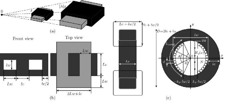
Fig. 1. (a) Homothetic Shape. (b) Charactersitics of a rectangular shape. (c) Charactersitics of a toroidal shape.
• The validity of the formulation is checked before launching the optimization itself. If a rule is not obeyed, it is pointed out
right from the start.
• Solvers for valid GP-form problems are fast and efficient, little knowledge is needed to use them.
II. GEOMETRIC PROGRAMMING
Geometric Programming (GP) is a mathematical optimization problem [7]. It has the following form: minimize:
(1) subject to:
(2) where x = (x1,x2,...,xn) is a vector of the design positive variables, hj(x) are the GP-monomials constraints, the coefficients aj are positive coefficients, and the exponents kj are any real number. However, in this standard formulation the posynomials and monomials are not convex function [9], and can be difficult to solve. However, translating them to the log domain makes them convex and easy to solve. Posynomial Functions:
log(h(x)) = log(axk11 ...xknn)
(3) = log(a)+ k1log(x1)+ ... + knlog(xn)
After such a transformation, the function presents a linear and convex behavior, which guarantees the existence of only one global optimized point. In the next sections we will show that the multi-objective optimization of an inductor aiming at finding the trade-off between power losses and volume, can be quickly solved as long as the formulation is a GP-valid problem [10].
III. INDUCTOR DESIGN BASED ON HOMOTHETIC SHAPE
An homothetic shape, as shown in Fig. 1 (a) has the advantage of being a linear transformation, which preserves not only the colinearity of points but also the vector addition and scalar multiplication. It means that the distances between points are proportional by a factor λ, areas by λ2, volumes to λ3, etc...
By considering fixed shapes of the magnetic cores, and modeling the core and winding losses, the presented approach relates these variable with the area product of the core and the winding (AwAc) [11]. The area product is proportional to the
TABLE I GEOMETRICAL FACTORS
Parameter Rectangular Shape Toroidal Shape
power P, which allows to scale the converter volume depending on the operating point. However, it is not easy to express all the core and winding parameters as function of the area product. Therefore, the approach of considering fixed shapes, with dimensions following an homothetic law, simplifies the modeling problem. This homothetic approach is mainly dedicated to standard magnetic cores (E, planar, ETD, toroidal, etc.). Even though the core dimension in a given family are not always homothetic, this approach allows finding the closest possible core.
A. Core Shape Specifications
In order to apply the methodology, the geometrical parameters must be expressed in terms of the area product. As a beginning step, three ratios are obtained to describe all the geometric parameters no matter the core geometry. A rectangular shape, as shown in Fig. Fig. 1 (b) [11] , or a toroidal shape, as shown in Fig. 1 (c) [12].
aw = Lw/lw
ac1 = Lc/lw (4) ac2 = lc/lw
where, Lw and lw are related to the winding distances, and Lc and lc with the core distances. These geometrical ratios allow defining the desired inductor characteristic in terms of the area product AwAc, but it is necessary to previously define some geometrical factors, for the rectangular and toroidal shape, as described in the Table I.
With these factors it is possible to express the inductor characteristic as follows:
• Core and winding areas:
Aw = Lwlw = awwc(AwAc)1/2
(5)
Ac = Lclc = acwc(AwAc)1/2 •
Effective inductor volume:
V olE = (Y + Z/Kw)(AwAc)3/4
Kw > 1
where, Kw represents a winding factor.
(6)
• Total exchange surface: 1/2
ATH = S(AwAc)
• Allowed losses:
(7)
Pwc = ATHHΔT (8) where, ΔT represents the thermal elevation above ambient temperature, and H is the thermal exchange coefficient. As can be seen, the volume and thermal losses have been described in terms of the area product AwAc.
IV. OPTIMIZATION PROBLEM USING GP FORMULATION The main rules governing the design of inductors are the following:
• A magnetic component stores energy through the interaction of a magnetic flux and a current (φ · I > Ltarget · I2). • The flux density cannot exceed a certain value (φ · Ac < Bsat).
• The current generates losses in the conductor, and the AC flux generates losses in the core; these losses must be dissipated through an exchange surface.
In order to address the optimization problem, the proposed procedure is presented in Fig. 2. At the beginning the user selects from a data base set, some standard parameters found in the commercial datasheets (e.g. the material of the core and winding, geometrical proportions based on the type of core, etc.). Then, the user defines the operating points under which the inductor will
work (e.g. nominal power, input/output voltage, switching frequency, etc). After that, the program will calculate some operation parameters based on the user selections, with these parameters all the geometrical and electrical characteristics are defined.
At first instance, the geometric programming formulation is constructed defining the target variables to be optimized gpvar. The selected variables regard the construction limitations AwAc, inductance requirement jDC and core saturation Bdc. The advantage of the GP is that there is not a theoretical limitation on the number of variables to be optimized, as long as the GP formalism is respected. Besides, all the constraints are imposed in this step. Where all the maximum allowed values can be also defined as a function of the variables to optimize NRJ or, physical limitations of the material Bsat. For concluding the first GP formulation, the objective is defined. The GP does not limit the number of objectives to be optimized at same time, but in this work the objectives are evaluated independently and consecutively. This will be justified in the following sections.
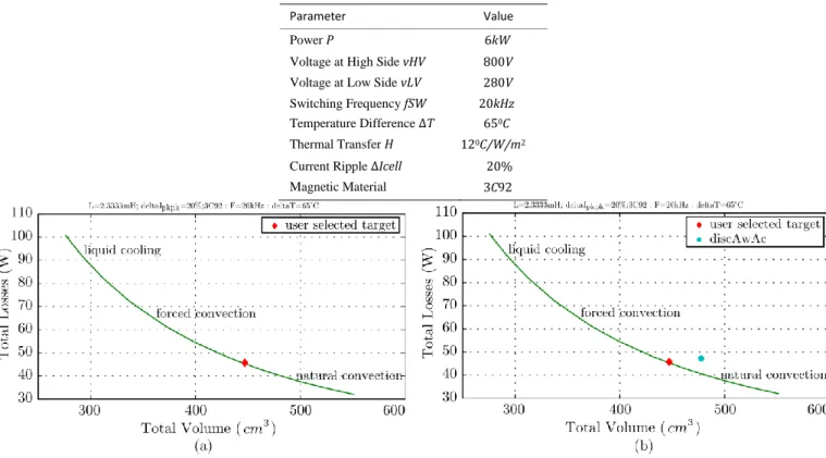
TABLE II EVALUATION PARAMETERS
Parameter Value
Power P 6kW
Voltage at High Side vHV 800V Voltage at Low Side vLV 280V Switching Frequency fSW 20kHz Temperature Difference ΔT 650C Thermal Transfer H 120C/W/m2
Current Ripple ΔIcell 20%
Magnetic Material 3C92
Fig. 3. (a) Volume/Losses Pareto Front, for continuous variables design. (b) Volume/Losses Pareto Front, selecting a feasible core design.
V. EVALUATION CASE
As an evaluation case the selected core is: a EI − Planar type, with a magnetic material MagneticsMPP300, and conductor
Copper, for a Chopper application. Moreover, the design parameters are presented in the Table II. A. GP Formulation in a Continuous Domain
At first instance, the GP formulation selects the area product as the optimization objective AwAc. Beside, the first assumption made is that rac/rdc = 1. It is made in order to know the volume/loss Pareto front under ideal conditions. The result depicted in
Fig. 3 (a), allows the designer to chose a desired operating condition on this design space. This selected target can be made based on the technique for the thermal dissipation (liquid cooling, forced convection or natural convection). In this case, the selected point is: Htherm = 13W/0C/m2, AwAc = 1.02623e6mm4, nTurns = 50.4397. However, as can be noted, the variables are
continuous (e.g. nTurns), and it must to be an integer value in order to construct the inductor.
B. GP Formulation for Feasible Variables
1) Feasible Core Design: Once the algorithm generates the Pareto front for continuous variables, the designer will be able to
(b), the designer was able to chose an available core. In this case, the selected point is: Htherm = 13W/0C/m2, AwAc = 1.12e6mm4,
nTurns = 52.1402
It means that the geometry proportion AwAc, is not a variable anymore, but it is an imposed parameter to be set on the GP formulation as follows:
• gpvar: jDC, Bdc ( AwAc now imposed to AwAcDisc ) • constraints: Inductance requirement NRJreq
≤ NRJ(AwAcDisc) Avoid saturation
Bmax≤Bsat(AwAcDisc) Respect thermal constraint totalLosses(AwAcDisc)≤ allowedLosses(AwAcDisc)
• objective: totalLosses(AwAcDisc)
2) Feasible Turns Ratio: After the optimization, the core is now slightly bigger than strictly required but it still has to truncate
the turns ratio nTurns. There are different ways to do this:
• nTurnsDisc=floor(nTurns): It increases Bmax, the core losses and wire section. But it decreases dc winding losses.
• nTurnsDisc=ceil(nTurns): It decreases Bmax, the core losses and wire section. But it increases dc winding losses.
It means that the turns ratio nTurns, is not a variable anymore, but it is an imposed parameter to be set on the GP formulation as similar to the explained above, with the difference that:
• gpvar: Bdc ( jDC is now imposed)
• constraints: Inductance requirement
Avoid saturation
Bmax≤Bsat(AwAcDisc, nTurnsDisc)
Respect thermal constraint totalLosses(AwAcDisc, nTurnsDisc)≤
allowedLosses(AwAcDisc)
• objective: totalLosses(AwAcDisc, nTurnsDisc)
In that evaluation, the selected operating points are depicted in Fig. 4. The values are: Htherm = 13W/0C/m2, AwAc =
1.12e6mm4, nTurns = 53. In case no acceptable design is found, the next bigger core must be selected.
C. Design using Finite Elements Analysis
The jDC/Bdc formulation does not involve the B(H) characteristic of the material; in this approach, the air gap is adjusted at the end of the design to obtain the appropriate induction level and inductance value. Therefore a non-linear B(H) characteristic can be easily taken into account since B and H are already known, as shown in Fig. 5 (a).
The air gap reluctance is found by subtracting the core reluctance (with μ(Bdc)) to the targeted total reluctance, as shown in Fig. 5 (b).
There are some motivations for using Finite Elements:
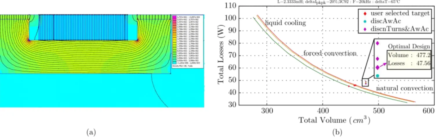
Fig. 6. (a) Flux density results using Finite Elements. (b) Optimization procedure of an inductor under user specifications.
• Relation from airgap to airgap reluctance is complex and involves details of the geometry (e.g. distance to the winding). •
AC losses are difficult to take into account (skin, proximity and air gap induced losses) and each formulation is geometry dependent.
Therefore, FEMM simulations are run to have a good estimate of rac/rdc and inductance L. The whole process is repeated until the correction coefficients become as close to 1 as specified. From the results, it was realized that 5% tolerance generally needs less than 4 iterations. Calculation time is around 1 minute, with roughly 99% for FEMM and 1% for GP formulation execution. The results of the FEMM analysis for the selected geometry, is depicted in Fig. 6 (a). In this figure it is possible to see the Flux Density B on the core.
Moreover, after 3 iterations, the results of the optimization process is depicted in Fig. 6 (b). In this figure, the desired operating points are highlighted, and from the results it is possible to see that for an inductor of 477.2cm3, a total power dissipation of 47.56W is achieved. The result assumes the designer will be able:
• To find an existing core and an integer number of turns close to the prescribed solution.
• To find the air gap that gives targeted L, accounting for fringing effect and for material non linearity. • To find a winding topology (round/litz, horizontal/vertical foil,) that gives the assumed rAC/rDC.
VI. CONCLUSIONS
This work presents a methodology for the optimal design of inductors, based on the homothetic shapes. Due to this criteria of designing, it is possible to represent all the geometrical and electrical characteristics of the inductor in terms of the area product.
Besides, the geometrical programming formalism is used as a powerful tool for the multi-objective convex optimization. Giving as result a volume/loss Pareto front, which allows to the designer to select the available core and turns ratio close to the prescribed solution.
Moreover, other advantage of the geometric programming formalism, is that this design is extremely fast (< 20ms). And it can be used, to explore the design space (weight/losses pareto, iteration on materials or shapes, variation of frequency,), at system level to get good estimates of weight and losses of magnetic components (e.g. in a full conversion chain).
REFERENCES
[1] U. Badstuebner, J. Biela, and J. W. Kolar, “An optimized, 99phase-shift pwm dc-dc converter for data centers and telecom applications,” in The 2010 International Power Electronics Conference - ECCE ASIA -, June 2010, pp. 626–634.
[2] U. Badstuebner, A. Stupar, and J. W. Kolar, “Sensitivity of telecom dc-dc converter optimization to the level of detail of the system model,” in 2011 Twenty-Sixth Annual IEEE Applied Power Electronics Conference and Exposition (APEC), March 2011, pp. 585–592.
[3] J. W. Kolar, J. Biela, and J. Minibock, “Exploring the pareto front of multi-objective single-phase pfc rectifier design optimization - 99.2efficiency vs. 7kw/din3power density,” in 2009 IEEE 6th International Power Electronics and Motion Control Conference, May 2009, pp. 1–21.
[4] A. Morentin, G. Fontes, M. M. Hillesheim, T. Meynard, D. Flumian, J. Bourdon, and H. Piquet, “Opencomp3d: An opensource framework dedicated to design in power electronics,” Mathematics and Computers in Simulation, 2018. [Online]. Available: http://www.sciencedirect.com/science/article/pii/S037847541830301X
[5] T. Sato, K. Watanabe, H. Igarashi, T. Matsuo, T. Mifune, K. Kawano, M. Suzuki, Y. Uehara, and A. Furuya, “3-d optimization of ferrite inductor considering hysteresis loss,” IEEE Transactions on Magnetics, vol. 49, no. 5, pp. 2129–2132, May 2013.
[6] A. Stupar, T. McRae, N. Vukadinovic, A. Prodic, and J. A. Taylor, “Multi-objective optimization and comparison of multi-level dc-dc converters using convex optimization methods,” in 2016 18th European Conference on Power Electronics and Applications (EPE’16 ECCE Europe), Sep. 2016, pp. 1–10. [7] S. Boyd, S.-J. Kim, L. Vandenberghe, and A. Hassibi, “A tutorial on geometric programming,” Optimization and Engineering, vol. 8, no. 1, p. 67, Apr
2007. [Online]. Available: https://doi.org/10.1007/s11081-007-9001-7
[8] Ggplab: A simple matlab toolbox for geometric programming. [Online]. Available: https://web.stanford.edu/ boyd/ggplab/
[9] A. Stupar, J. A. Taylor, and A. Prodic, “Posynomial models of inductors for optimization of power electronic systems by geometric programming,” in 2016 IEEE 17th Workshop on Control and Modeling for Power Electronics (COMPEL), June 2016, pp. 1–8.
[10] A. Stupar, M. Halamicek, T. Moiannou, A. Prodic, and J. A. Taylor, “Efficiency optimization of a 7-switch flying capacitor buck converter power stage ic using simulation and geometric programming,” in 2018 IEEE 19th Workshop on Control and Modeling for Power Electronics (COMPEL), June 2018, pp. 1– 8.
[11] F. Forest, E. Laboure, T. Meynard, and M. Arab, “Analytic design method based on homothetic shape of magnetic cores for high-frequency transformers,” IEEE Transactions on Power Electronics, vol. 22, no. 5, pp. 2070–2080, Sept 2007.
[12] F. Forest, E. Labour, T. A. Meynard, and V. Smet, “Design and comparison of inductors and intercell transformers for filtering of pwm inverter output,” IEEE Transactions on Power Electronics, vol. 24, no. 3, pp. 812–821, March 2009.