HAL Id: hal-01347681
https://hal.archives-ouvertes.fr/hal-01347681
Submitted on 21 Jul 2016
HAL is a multi-disciplinary open access
archive for the deposit and dissemination of
sci-entific research documents, whether they are
pub-lished or not. The documents may come from
teaching and research institutions in France or
abroad, or from public or private research centers.
L’archive ouverte pluridisciplinaire HAL, est
destinée au dépôt et à la diffusion de documents
scientifiques de niveau recherche, publiés ou non,
émanant des établissements d’enseignement et de
recherche français ou étrangers, des laboratoires
publics ou privés.
Guiding pancreatic beta cells to target electrodes in a
whole-cell biosensor for diabetes
Eileen Pedraza, Aleksandar Karajić, Matthieu Raoux, Romain Perrier,
Antoine Pirog, Fanny Lebreton, Stéphane Arbault, Julien Gaitan, Sylvie
Renaud, Alexander Kuhn, et al.
To cite this version:
Eileen Pedraza, Aleksandar Karajić, Matthieu Raoux, Romain Perrier, Antoine Pirog, et al.. Guiding
pancreatic beta cells to target electrodes in a whole-cell biosensor for diabetes. Lab on a Chip, Royal
Society of Chemistry, 2015, 15, �10.1039/C5LC00616C�. �hal-01347681�
CNRS Laboratories of Chemistry and Biology (UMR 5248CBMN), of Molecular Sciences (UMR 5255 ISM) and of System
Integration (UMR 5218IMS), that collaborate in an excellence cluster (Labex Amadeus) to develop novel islet cell-based biosensors for diabetes research and therapy. Picture courtesy to Dr Y. Bornat, IMS.
Title: Guiding pancreatic beta cells to target electrodes in a whole-cell biosensor for diabetes
Development of novel islet cell-based sensors for diabetes therapy requires an optimal match between arrayed microelectrodes and cells. This has been achieved here by electrophoresis of cells using commercial compounds. The final set-up permits automated signal recognition and treatment.
See Jochen Lang et al. Lab Chip, 2015, 15, 3880.
Lab on a Chip
PAPER
Cite this:Lab Chip, 2015, 15, 3880
Received 3rd June 2015, Accepted 4th August 2015 DOI: 10.1039/c5lc00616c www.rsc.org/loc
Guiding pancreatic beta cells to target electrodes
in a whole-cell biosensor for diabetes
†
Eileen Pedraza,abAleksandar Karajić,cdMatthieu Raoux,abRomain Perrier,ab Antoine Pirog,deFanny Lebreton,abStéphane Arbault,cdJulien Gaitan,ab Sylvie Renaud,deAlexander Kuhncdand Jochen Lang*ab
We are developing a cell-based bioelectronic glucose sensor that exploits the multi-parametric sensing ability of pancreatic islet cells for the treatment of diabetes. These cells sense changes in the concentration of glucose and physiological hormones and immediately react by generating electrical signals. In our sen-sor, signals from multiple cells are recorded as field potentials by a micro-electrode array (MEA). Thus, cell response to various factors can be assessed rapidly and with high throughput. However, signal quality and consequently overall sensor performance rely critically on close cell–electrode proximity. Therefore, we present here a non-invasive method of further exploiting the electrical properties of these cells to guide them towards multiple micro-electrodesvia electrophoresis. Parameters were optimized by measuring the cell's zeta potential and modeling the electric field distribution. Clonal and primary mouse or human β-cells migrated directly to target electrodes during the application of a 1 V potential between MEA electrodes for 3 minutes. The morphology, insulin secretion, and electrophysiological characteristics were not altered compared to controls. Thus, cell manipulation on standard MEAs was achieved without intro-ducing any external components and while maintaining the performance of the biosensor. Since the analy-sis of the cells' electrical activity was performed in real timevia on-chip recording and processing, this work demonstrates that our biosensor is operational from the first step of electrically guiding cells to the final step of automatic recognition. Our favorable results with pancreatic islets, which are highly sensitive and fragile cells, are encouraging for the extension of this technique to other cell types and microarray devices.
1 Introduction
The first biosensor to be described was an amperometric enzyme electrode for glucose,1 and currently an overwhelm-ingly large part of the market for bioelectronic sensors is dominated by blood glucose sensors for the management of diabetes.2,3This reflects a strong demand for precise and fre-quent monitoring to stabilize glucose levels because correct dosing of insulin can reduce disease-associated effects, such as blindness, amputation, and kidney or organ failure.4 How-ever, sensors that measure glucose exclusively can show
limitations because the body's demand for insulin is influenced by many factors in addition to glucose, such as hormones or other nutrients.5,6Biosensors capable of consid-ering these additional factors in the estimation of insulin demand would be highly advantageous. Whole-cell biosensors are particularly attractive due to their ability to integrate mul-tiple inputs,7but the field has been mostly limited thus far to monitoring of environmental toxins and clinically relevant parameters, with no immediate implementation in the clinic documented yet.8–11Moreover, there is a demand for smaller biosensors for greater portability and eventually for implantation. Our group is developing a whole-cell biosensor for the treatment of diabetes that exploits the multi-parametric sens-ing ability of β-cells, which are the insulin-secreting cells of pancreatic islets. β-Cells sense glucose and metabolize it to secrete insulin. Glucose metabolism is a multi-step process that involves the production of ATP, which triggers the open-ing and closopen-ing of potassium and calcium ion channels. Con-sequently, potassium and calcium ions flow across the cell membrane and produce an electric current. Various hor-mones and drugs can bind to receptors on the cell mem-brane, influence glucose metabolism, trigger ion channel
a
CNRS UMR 5248, Chimie et Biologie des Membranes et Nano-objets, Allée Geoffroy Saint-Hilaire, Pessac, France
b
Université de Bordeaux, Département Sciences et Technologie, Av de la Libération, Talence, France. E-mail: jochen.lang@u-bordeaux.fr
c
CNRS UMR 5255, Institut des Sciences Moléculaires, 16 Avenue Pey Berland, Pessac, France
d
Bordeaux Institut National Polytechnique, Avenue des Facultés, 33405 Talence, France
e
CNRS UMR 5218, 351 Cours de la Libération, Talence, France
† Electronic supplementary information (ESI) available. See DOI: 10.1039/ c5lc00616c
opening, and consequently alter the electric current. Our bio-sensor uses micro-electrode arrays (MEAs) to record these elec-trical signals produced byβ-cells in response to multiple envi-ronmental factors (glucose, lipids, hormones, etc.). The cells' response to changes in glucose concentration manifests itself in changes in the frequency of the recorded signals.12–14These extracellular signals are robust and are also influenced by the presence or absence of physiologically relevant hormones and drugs.12–14Compared to traditional glucose sensors, this bio-sensor offers high temporal resolution in real time since the frequency of the recorded signal changes quickly in response to changes in the environment. Entire islets, which are cell clusters measuring 50 to 300 μm in diameter, or individual islet cells measuring around 10 μm in diameter can be assessed by varying the size or spacing of micro-electrodes within the microscale range. The array layout and small inter-electrode spacing allows for high sample throughput as well as investigation of interactions between neighboring cells.
In the immediate future, this biosensor can be used ex vivo for rapid quality assessment of islet cells from deceased donors prior to their transplantation in the case of type 1 diabetes. Other applications are for online monitoring of stem cells during differentiation or for pharmacological screening to reduce animal experiments. In the long run, the same technology can be part of an artificial organ ex vivo or in vivo to realize closed-loop sensing as implantable biosen-sors that drive insulin pumps.6In both applications, immedi-ate and long-term ones, only a few cells or islets are needed, in stark contrast to the several millions of islets required for transplantation. In the case of an artificial organ, these cells or islets may be obtained from deceased human donors or from appropriate animal sources.
Signal quality and consequently overall sensor perfor-mance rely critically on good contact between cells and electrodes.7,8 Signal detection in cell-based biosensors has been greatly improved by reducing interference from encap-sulation polymers,15,16 controlling cell placement,17,18 and increasing cell attachment to the sensing substrate.19For our whole-cell biosensor in particular, close cell–electrode prox-imity is vital to acquiring a detectable signal.12–14Pancreatic islets are rare and valuable since they must be isolated from a human donor. Therefore, we want to minimize the number of cells needed and develop a method of cell manipulation to place the cells on the electrodes in a standardized manner. Label-free techniques for controlling the placement of cells may employ different forces: acoustic,20ultrasonic,21 electri-cal via dielectrophoresis,22mechanical,23 or optical (“optical tweezers”).24 Surface modification with adhesive proteins is simple to implement but offers less control and precision over the final placement of the cells.25Microfluidics methods as well as negative pressure and suction methods may gener-ate significant hydrodynamic stress resulting in cell deforma-tion26,27or cell rupture28and require highly customized set-ups. Dielectrophoresis (DEP) can distinguish between cell types with different polarities but requires extensive instru-mentation and the introduction of multiple additional
electrodes in a complex layout, thus hindering its application to pre-existing MEAs and biosensors.29,30DEP may also over-heat samples,31 and the high-frequency signals may cause electroporation and electrofusion.32,33Moreover, unless high frequencies and very low-conductivity buffers are used, DEP moves particles away from target electrodes rather than towards them, making it undesirable for our purpose.34
Since electrophoresis is better suited than DEP for migra-tion of particles over long distances (up to centimeters) and does not require a complicated set-up,34 it can be readily implemented into pre-existing MEAs. Previous work has focused on measuring electrophoretic mobilities or migrating the cells just over a short distance (fractioning cells),35,36 whereas the final goal of the present contribution is to bring the cell into close contact with the target electrode. Ozkan et al. nicely demonstrated that mouse neural stem cells could be spatially manipulated via electrophoresis and maintained normal morphology and proliferation rate.37 They designed and created a customized electro-optical platform for this purpose but the same principle could be implemented into biosensors by cleverly selecting the optimal electrode layout for introducing the electric field. However, the question remains unanswered as to how these electric fields might affect cells in other more subtle ways that do not manifest themselves in such gross changes. This is particularly impor-tant in the context of biosensors, where it is crucial that the cells maintain their normal function and behavior so that the biosensor can function properly.
We present here a non-invasive method of further exploiting the electrical properties of islet cells to guide them directly towards electrodes via simple electrophoresis. This work is the first to implement electrophoresis for spatial manipulation of cells directly into a biosensor. Moreover, our method uses commercial, readily available MEAs and does not require any components to be introduced into the sys-tem. We demonstrate that after spatial manipulation by electrophoresis, both primary and human cells retain normal behavior, resulting in a functional biosensor.
2 Materials and methods
2.1 Chemicals
Chemicals were purchased from Sigma (Sigma, St. Louis, MO, USA) except for glucagon-like peptide-1 (GLP-1) (Bachem Bioscience, King of Prussia, PA, USA). Nifedipine and glibenclamide were solubilized in dimethyl sulfoxide and adrenaline in ascorbic acid. The solvents (final concentra-tions≤0.1%, v/v) did not affect electrical signals.
2.2 Islet isolation and cell culture
The pancreatic clonal β-cell line INS832/13 was kindly pro-vided by Dr. C. Newgard, (Duke University School of Medi-cine, NC, USA),38cultured as published,12and used for exper-iments between the 50th and the 80th population doubling (PD), which indicates how many times the population has doubled in number. Adult (8–20 weeks) male C57BL/6 mice
were killed in accordance with the ethical rules concerning animal care of the University of Bordeaux. Mouse islets were isolated, dissociated, and cultured for 3 days on MEAs, as previously described.14,39 Isolation was performed by extracting the pancreas, injecting it with 2 ml of collagenase NB 8 (1.1 PZ-U per ml, Serva Electrophoresis, Heidelberg, Germany) via cannulation through the pancreatic duct, cut-ting it into 1–2 mm pieces, and letting it be digested for 11 min at 37 °C. The islets were then hand-picked to separate the endocrine tissue from the exocrine tissue. Dissociation was performed by incubating the islets in 0.1 mM trypsin– EDTA (Invitrogen, Carlsbad, CA) for 2 min at 37°C and sub-sequently pipetting up and down 20 times to break the islets up into individual cells. Human islets (90% purity, non-dia-betic, 60 years, female, 21.5 BMI) were isolated and kindly provided by the Geneva Cell Isolation and Transplantation Center. Dissociation was performed by incubating the islets in Accutase (Fisher Scientific, Illkirch-Graffenstaden, France) for 6 min 30 s at 37°C while pipetting up and down for 15 s every 45 s.
2.3 Preparation of low-conductivity buffer
The conductivity of the incubating solution was reduced by decreasing the concentration of ions in the solution and substituting them with nonionic solutes to maintain an osmotic pressure suitable for biological cells (270–300 mOsm L−1). Mannitol was selected to balance the osmolarity because it does not affect glucose-induced insulin secretion.40 There-fore, a custom buffer composed of 5 mM HEPES IJ4-IJ2-hydroxyethyl)-1-piperazineethanesulfonic acid), 270 mM man-nitol, and 5 mM glucose was formulated. The osmolarity of the solution was measured using an Automatic Micro-Osmometer Type 15 (Löser Messtechnik, Berlin, Germany). The pH of the solution was determined using a 0.1% bromo-thymol sulfone phthalein, (BTB) solution in 20% ethanol. The conductivity of the solution as well as the zeta potential of the polystyrene spheres and INS832/13 cells was measured using a disposable, capillary folded chamber and a Zetasizer Nano ZS apparatus (Malvern Instruments Ltd, Worcester-shire, UK).
2.4 Cell viability and insulin secretion in low-conductivity buffer
Immediately after cell preparation, all cells were washed three times with the low-conductivity buffer to remove resid-ual ions and were suspended in this buffer. The short-term and long-term effects of this buffer on clonal INS832/13 β-cells were investigated. To investigate the long-term effects, INS832/13 cells were first incubated in either cell culture medium or low-conductivity buffer at a density of 5.5× 10⁶ cells per mL for 30 min and subsequently assessed for viabil-ity and function. The viabilviabil-ity and metabolism of cells was assessed by incubating cells in a 48-well plate for 24 h and performing an MTT CellTiter96 Non-Radioactive Cell Prolifer-ation Assay (Promega, Madison, WI, USA) according to the
manufacturer's protocol. Insulin secretion was assessed by culturing cells on an adherent 24-well plate for 72 h and performing a glucose stimulus test during which cells are incubated in glucose (either 3 or 15 mM) for 30 min and incubating solutions are subsequently collected, as published previously.39Insulin content was quantified by an ELISA kit (Mercodia AB, Uppsala, Sweden) and normalized by total pro-tein, which was quantified by a Pierce BCA Protein Assay kit (Thermo Scientific, Rockford, IL, USA). To investigate the short-term effects, a modified glucose stimulus test was performed on INS832/13 cells grown on an adherent 24-well plate in normal culture medium for 72 h. For this modified test, glucose incubation solutions were prepared in either Hank's Balanced Salt Solution (HBSS) (control) or low-conductivity buffer. Insulin samples were collected after 30-min incubation.
2.5 Micro-electrode arrays (MEAs)
Studies were performed with two types of MEAs (Qwane Bio-sciences SA, Lausanne, Switzerland): MEA60-4Well-Pt for polystyrene spheres or clonal INS832/13 β-cells and 100-30-Pt for mouse or human islet cells. MEA60-4Well-Pt consists of 4 cylindrical Plexiglas chambers (6 mm diameter, 8 mm height), each housing 15 recording electrodes (30μm in diameter and spaced 100 μm apart) and one internal reference electrode. MEA60-100-30-Pt consists of one cylindrical glass chamber (24 mm diameter, 6 mm height) housing 59 recording electrodes (40μm in diameter and spaced 200μm apart) arranged in an 8 × 8 matrix with-out corner electrodes and one internal reference electrode. Platinum metal was selected as the electrode material, despite its relatively high impedance (800–1100 kΩ), because it allows positive bias to be injected into the electrode with-out causing significant degradation. The substrate material was glass and the insulation material was SU-8 epoxy (5 μm thick). The MEA surface was rendered hydrophilic by plasma treatment with air at 9.83 W L−1for 2 min; it was prepped for cell culture by coating with Matrigel (2%, v/v, BD Biosciences, San Diego, CA, USA).
2.6 Computational modeling of electric field
The optimal configuration for applying an electric potential to the sensor electrodes was determined by computational modeling. The distribution of the resulting electric field in the sensor was calculated by finite element analysis using the software COMSOL Multiphysics (COMSOL, Stockholm, Swe-den). Electric currents AC/DC module was used to solve the following Poisson equation: ∇·(σE + Je) = Qj where σ is the electrical conductivity of the medium, E is the electric field, Jeis the external current density vector, and Qjis the current source. The electric field is given by the following equation: E =−∇V. The velocity of particles with a charge, q, is directly proportional to the electrophoretic force, F, described by: F = qE. Neumann boundary conditions (n·J = 0) were used for the insulating layer and chamber edges. An electric potential
(varied from 1 to 2.5 V) was applied to select electrodes and the remaining electrodes were designated as ground (V = 0). 2.7 Spatial manipulation by electrophoresis
An electric field was produced by applying an electric poten-tial difference between neighboring electrodes. The electric potential was generated using an EmStat 3 potentiostat (PalmSens BV, Utrecht, Netherlands) with the working electrode acting at the positive potential and the counter electrode short circuited with the reference electrode acting at the negative potential. The electrophoresis of negatively charged round particles was investigated using uniform dyed polystyrene microspheres IJPIJS/2% DVB)) of 10 μm diameter (Bangs Laboratories Inc., Fishers, IN, USA). Time-lapse images and videos were acquired using a Leica DFC295 digi-tal camera mounted on a Leica MSV266 stereoscopic micro-scope and the Leica Application Suite (LAS) v4.3.0 (Leica, Heerbrugg, Switzerland). The efficacy of the treatment was determined by counting the number of cells on each electrode before and immediately after application of the potential. After 3-day culture, cell viability was quantitated with the LIVE/DEAD Cell Imaging Kit (Life Technologies, Eugene, OR, USA), which produces green fluorescence in live cells (ex/em 488 nm/515 nm) and red fluorescence in dead cells (ex/em 570 nm/602 nm). The kit was used according to the manufacturer's protocol by incubating cells in equal vol-umes of cell culture medium and 2× stock solution for 15 min at 20 °C, and fluorescence was viewed using FITC and TRITC filters.
2.8 Electrophysiology and signal analysis
Extracellular recordings were performed at 37°C in a physio-logical buffer containing (in mM): 135 NaCl, 4.8 KCl, 1.2 MgCl2, 1.2 or 1.8 CaCl2, 10 HEPES and glucose as indicated (pH 7.4, adjusted with NaOH).14,41Simultaneous analog data were acquired at 10 kHz per electrode using a MEA1060-Inv-BC-Standard amplifier (Multichannel Systems; gain: 1100; analog filter: 0.1− 3000 Hz). Recordings were analyzed in real time using a customized recording and processing board developed by our group and offline using MC_Rack software (Multichannel Systems). In both cases, a 0.2−700 Hz second-order Butterworth digital filter was applied and used to show representative traces. For offline determination of frequen-cies, slow potentials, which have been previously character-ized,14,41were extracted using a 0.2−2 Hz band-pass filter and detected using the threshold module of MC_Rack with a dead time (minimal period between two events) set to 500 ms. For each condition, slow potential frequencies were mea-sured at steady state (last 3 min of application). The board performs multiple steps, all in real time, to detect and ana-lyze slow potentials. First, it detects when the signal ampli-tude exceeds a threshold value and identifies minima and maxima based on amplitude criteria. Then, it qualifies a pair of minima and maxima as a slow potential when the timing between them is of a sufficient duration. Signal-to-noise ratio
(SNR) measurements were performed on the recordings. It was considered that the signal of interest was that of the slow potentials, obtained by band-pass filtering at 0.2–2 Hz. Zero-phase Butterworth filters were used to extract it in order to compensate for phasing issues with the noised signal. Mea-surements were thus performed for each electrode on two phase-aligned signals: the nonfiltered signal as recorded by the system (containing noise) and the slow-potential signal (noise filtered out).
2.9 Statistics
Experiments with pancreatic mouse islet cells were replicated on at least 2 MEAs, each covered with cells obtained from dif-ferent mice. Results are presented as means and SEM of n electrodes. Two-way ANOVA with Sidak post hoc correction was used for comparisons between more than two groups.
3 Results and discussion
3.1 Islet-based biosensor
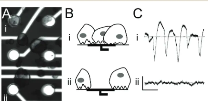
Pancreatic islet cells are loaded into MEAs and settle ran-domly, resulting in only a limited number of electrodes being covered with cells (Fig. 1A). Cell-covered electrodes capture changes in the islet field potential that arise upon exposure to glucose (Fig. 1B and C, top row). In contrast, electrodes with either poor or no cell-contact do not record any specific signals (Fig. 1B and C, bottom row). For that reason, we explored the possibility of using electrophoresis to guide islet cells to recording electrodes.
3.2 Biocompatibility of low-conductivity buffer
Electrophoresis requires particles to be suspended in a buffer of low conductivity to avoid heat generation, ion depletion,
Fig. 1 Principle of the islet-based biosensor:β-cells are cultured on a micro-electrode array (MEA) that records the cells' electrical activity in response to glucose, drugs, and hormones in the incubating solution. (A) Microscope image of a 3-day-old mouse islet cell culture on a MEA showing (i) electrodes covered with cells and (ii) electrodes not cov-ered with cells. Electrode diameter: 30μm. (B) Schematic of cell cover-age on electrodes. (C) Electrode recordings of glucose-induced elec-trical activity. Scale bars: horizontal 2 s, vertical 100 μV; dotted line: zero voltage. (i) Electrodes in close contact with cells record signals with a high signal-to-noise ratio, whereas (ii) poor contact between cells and electrodes due to random cell loading results in an inability to record electrical activity.
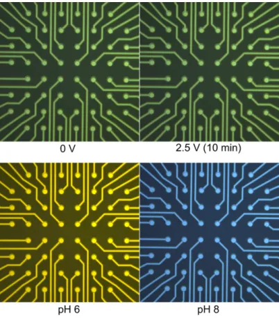
and pH changes.42We made a custom buffer with an osmo-larity of 280 mOsm L−1and a conductivity of 0.01 mS cm−1 that was suitable for both the tonicity of biological cell mem-branes and the electrophoretic manipulation. The pH of the solution by visual assessment with BTB was around 7–7.5 and was unaffected by application of 2.5 V for 10 min (Fig. S1†). Low-conductivity buffers may induce cell swelling, so we investigated the short-term and long-term effects of our custom buffer on clonal INS832/13 β-cells. In particular, we measured the cells' insulin secretion, which is the end-product of multi-step metabolic processes and is highly sen-sitive to slight variations in the concentration of calcium.43 Insulin secretion in response to low (3 mM) and high (15 mM) glucose concentrations was determined and calculated as percent of total content (Fig. S2†). Incubating cells in low-conductivity buffer for 30 min did not impair the insulin sec-retion of INS832/13 cells in the short term (0.16 ± 0.01% and 1.09 ± 0.14% of total insulin secreted at 3 mM (G3) and 15 mM (G15), respectively; fold increase: 6.97 ± 2.20; n = 3) (Fig. S2A†). Also, after 72 h of culture, insulin secretion was better than in controls (Fig. S2B†). We observed a decrease in con-tent by 29.54 ± 3.48% in cells incubated in low-conductivity buffer; however, the difference was not significant. We also determined the metabolic activity using the MTT assay, which mainly reflects the activity of NADIJP)H-dependent oxi-doreductases.44Similarly to secretion, the metabolic activity of treated cells 24 h later was not lower than that of control cells (Fig. S2C†).
3.3 Characterization of electric charge at the surface of clonal INS832/13β-cells
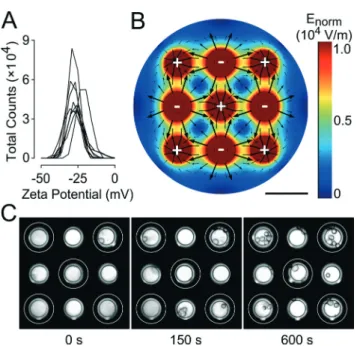
The zeta potential of clonal INS832/13β-cells was measured in low-conductivity buffer to determine the electric charge present at the cell surface. As the distribution chart for the zeta potential of INS832/13 cells in Fig. 2A shows, the cells had an average zeta potential of −27.0 ± 1.4 mV (standard deviation) (n = 9). These results are in agreement with the values obtained for other mammalian cells.37The zeta poten-tial of polystyrene spheres, which were used as model parti-cles, was strongly negative (−76.6 ± 1.5 mV, n = 3) due to the presence of charged sulfonate groupsIJRSO2O−) (Fig. S3A†).45 The low level of variability in the measured values indicates the uniformity of these spheres. This permitted us to use polystyrene spheres for preliminary testing.
3.4 Design strategy for electrophoresis in MEA
Electrophoretic patterning of cells typically requires many components, such as external electrodes and micromanipula-tors, to be added to a set-up.37 We sought to eliminate the need for any external elements and to implement an electric field directly into MEAs using only pre-existing electrodes. With this goal in mind, we performed finite element analysis to determine between which electrodes to apply an electric potential to produce the strongest electric field.
The final configuration chosen was a “neighboring electrode” configuration where adjacent electrodes were subjected to a potential difference of 1 (Fig. 2B), 1.5, 2.0, or 2.5 V (Fig. S4†). This configuration allowed the shortest dis-tance between oppositely charged electrodes and conse-quently the strongest field maxima possible. This is impor-tant because cells are only weakly charged and therefore require fields to be sufficiently strong to induce electropho-retic movement. The computational model shows the calcu-lated electric field distribution, where the field strength is indicated by the color gradient and the direction of the field is indicated by the black arrows. The electric field is stron-gest (red areas) near the electrodes and will cause cells to move quickly. Conversely, the electric field is weakest (dark blue areas) at the midpoint between electrodes of the same polarity, which means that cells in this area will be only weakly affected by the field and move slowly, if at all. The scarcity and small scale of the arrows in this area suggests that the motion of the cells in this area is difficult to pre-dict. The arrows indicate that the cells, which exhibit a neg-ative surface charge, will move away from the negneg-atively charged electrodes and toward the positively charged electrodes.
Fig. 2 Proof of principle for implementation of electrophoresis to spatially manipulate cells in micro-electrode arrays (MEAs). (A) Distri-bution chart of the measured zeta potential of clonal INS832-13 β-cells showing the total count of cells exhibiting a given zeta poten-tial. Each curve corresponds to one sample of 2.0× 10⁶cells per mL (n = 9). (B) Computational model of 1.5 V electric potential applied between neighboring electrodes in MEAs (charge on electrodes is indi-cated by plus and minus signs). The distribution of the electric field is shown with the direction indicated by arrows and the intensity indi-cated by the color legend, with zero strength being dark blue and maximum strength being red. Scale bar: 100 μm. (C) Time-lapse images showing gradual migration of INS832/13 cells in MEAs when exposed to a 1.5 V electric potential (positively charged electrodes indicated by white rings and negatively charged electrodes unmarked). Electrode diameter: 40μm.
The model allows the electrode configuration to be opti-mized by providing valuable insight into how cells will migrate in the MEA under idealized conditions. In practice, other factors, such as hydrophobic interactions between the cells and the MEA surface, will influence cell movement, thus necessitating experimental trials.
3.5 Electrophoresis of clonal INS832/13β-cells
As a proof of principle, we tested the electrophoresis of poly-styrene spheres in this configuration. As expected, polysty-rene spheres subjected to the field were quickly repelled from negatively charged electrodes and gathered over positively charged electrodes as shown in Fig. S3B.† We then investi-gated the electrophoretic migration of clonal INS832/13 β-cells under these same conditions. Time-lapse images showed the gradual migration of the cells towards positively charged electrodes, following the electric field lines calcu-lated by the computational model (Fig. 2C). The cells were clearly clustering around the target electrodes after just 60 s exposure to the electric field generated by applying 1.5 V. Most of the cell movement occurred within the first 3 min and the target electrodes were covered evenly with cells. INS832/13 cells moved more slowly in comparison to polysty-rene spheres. This may be due to the weaker electric charge of the cells (−27 mV vs. −77 mV) or their higher density, which increases drag forces and counteracts the electropho-retic force. The observed movement was due primarily to electrophoresis alone and is in contrast to other work that relies on both electrophoresis and dielectrophoresis to con-centrate much smaller cells, such as bacteria, on electrodes.46
3.6 Effect of field strength on the density of clonal INS832/13 β-cells over electrodes
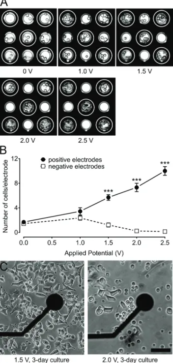
We sought to determine the minimum potential necessary to attract clonal INS832/13 β-cells to target electrodes. INS832/ 13 cells were loaded into MEAs and exposed to various poten-tials: 0, 1.0, 1.5, 2.0, and 2.5 V for 10 min (Fig. 3A). The num-ber of cells present on each electrode was counted at the beginning and end of each trial. Comparisons were made between the cell quantities on positively charged versus nega-tively charged electrodes (Fig. 3B). Fig. 3 shows that in the absence of an applied potential, the number of cells present on all electrodes was comparable. Application of a 1.0 V potential resulted in a two-fold increase in the cell coverage of positively charged electrodes. As greater potentials were applied, the number of cells on positively charged electrodes continued to increase at a rate of 4.26 cells per electrode per V (linear curve fit, R2= 0.99). It is important to note that cells migrating to positively charged electrodes were originally sit-uated in the area between the electrodes and not necessarily over negatively charged electrodes. In contrast, the cell cover-age of negatively charged electrodes decreased at a rate of −1.52 cells per electrode per V (linear curve fit, R2 = 0.91). Negatively charged electrodes became bare when 2.0 V or
Fig. 3 Influence of applied potential on cell-coverage of electrodes. (A) Images of clonal INS832/13 β-cells on a micro-electrode array (MEA) after 10 min exposure to various electric potentials: 0, 1, 1.5, 2, and 2.5 V (positively charged electrodes indicated by white rings and negatively charged electrodes unmarked). Electrode diameter: 40μm. (B) Number of INS832/13 cells present on positively charged (full circles) and negatively charged (open squares) electrodes after 10 min exposure to the electric field. Statistics:*** indicates p < 0.001 (n = 32 electrodes for 0 and 1.5 V,n = 16 electrodes for 1 and 2 V, and n = 8 electrodes for 2.5 V). (C) Influence of applied potential on the mor-phology of cells. Images showing differences in the mormor-phology of INS832/13 cells 2 days after a 10 min exposure to an electric potential of 1.5 and 2 V. Scale bar: 50μm.
more was applied. The ratio of cell coverage on positively charged electrodes compared to negatively charged electrodes increased considerably from 1.18 at 0 V to 4.68 at 1.5 V and then increased at a rate of 65.32 V−1between 1.5 V and 2.5 V (linear curve fit, R2= 0.91). Therefore, increasing the applied potential resulted in both an increase in cell coverage of electrodes as well as in greater selectivity over which electrodes were covered. However, achieving maximum cell coverage is not necessarily desirable since only a few cells are necessary to generate detectable signals and overcrowding of beta cells may introduce barriers to nutrient diffusion.
3.7 Effect of electric field on the morphology of clonal INS832/13β-cells
We were concerned with the potentially detrimental effects of exposure to an electric field since excessively strong electric fields can harm cells, causing electroporation, etc.47–49 How-ever, it is also important to have an electric field that is suffi-ciently strong to displace the cells. We sought to determine the maximum potential that could be applied before morpho-logical changes would be detected. Clonal INS832/13 β-cells were loaded into the MEA and subjected to various poten-tials: 0, 1.5, 1.75, or 2 V for 10 min. After 3 days in culture, cell morphology was examined using an inverted light micro-scope, which only permitted cells around and not directly above the electrodes to be examined. Cell morphologies for 1.5 V and 2.0 V are shown in Fig. 3C (0 and 1.75 V not shown). Control cells adhered well to the MEA surface and stretched across. This normal behavior was also observed for cells exposed to up to 1.5 V. On the other hand, cells subjected to 1.75 V and 2 V exhibited decreased adherence and reduced proliferation. Blebbing and membrane exten-sions were also visible, indicating a detrimental effect of such a high potential. In addition to morphological assessment, live and dead cells were identified and quantitated by the LIVE/DEAD kit (Fig. S5†). Intracellular esterase activity in live cells caused green fluorescence in the cytoplasm, while dam-aged cell membranes in dying and dead cells caused red fluo-rescence in the nucleus. The number of live cells was slightly lower for groups exposed to 1.5 V (168 cells) or 1.75 V (162 cells) compared to the untreated group (187 cells) and even lower for the group exposed to 2.0 V (140 cells). The number of dead cells was not drastically different between the untreated group and the 1.5 V group (43 cells compared to 60 cells, respectively). However, exposure to 1.75 V and 2.0 V resulted in dramatically more dead cells (141 and 169, respec-tively), suggesting that many cells were damaged by the high potential and died soon after. The observation that higher potentials did not have as profound of an effect on the num-ber of live cells can be explained by the fact that cells were exposed to different electric field strengths depending on their position in the MEA. This could have led to heterogene-ity in the cell population where cells exposed to the highest field strength died soon after and cells exposed to the lowest field strength were unaffected and able to grow. Therefore,
potentials should remain at or below 1.5 V to avoid harming INS832/13 cells.
3.8 Effect of field strength on the density of murine islet cells over electrodes
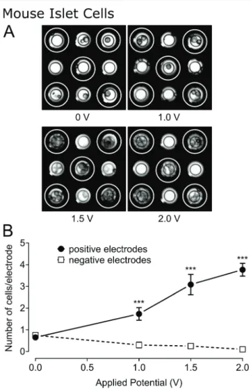
Our main goal is to use electrophoresis for the manipulation of pancreatic islets, either whole or dissociated, as these cells are representative of the native environment. Pancreatic islets are typically less robust and more sensitive to stress than clonalβ-cells and may behave differently in the same electric field. Therefore, we investigated the migration of dissociated mouse islets in the MEA after the application of different electric potentials: 0, 1.0, 1.5, and 2.0 V. After 10 min applica-tion of the potential, photographs were taken (Fig. 4A) and
Fig. 4 Influence of applied potential on mouse islet cell-coverage of electrodes. (A) Images of mouse islet cells on a micro-electrode array after 10 min exposure to various electric potentials: 0, 1, 1.5, and 2 V (positively charged electrodes indicated by white rings and negatively charged electrodes unmarked). Electrode diameter: 30 μm. (B) Chart showing the number of mouse islet cells present on positively charged (closed circles) and negatively charged (open squares) electrodes after 10 min exposure to electric field. Statistics:*** indicates p < 0.001 (n = 60 electrodes for 0 V, n = 30 electrodes for 1 V and 2 V, and n = 12 electrodes for 1.5 V).
the cells on each electrode were counted (Fig. 4B). In the absence of an applied potential, the number of cells present on the different electrodes was comparable (0.65 ± 0.11 and 0.75 ± 0.11 cells per electrode, respectively). Cell coverage of positively charged electrodes increased by a factor of 2.66 after the application of 1.0 V and continued to increase at a rate of 2.0 cells per electrode per V (linear curve fit, R2= 0.97) as the potential was further increased. In contrast, cell cover-age of negatively charged electrodes decreased at a rate of −0.2 cells per electrode per V (linear curve fit, R2= 0.92).
A 2 V potential was applied to the MEA for 1 min using the neighboring-electrode configuration. As expected, the cells migrated away from the negatively charged electrodes and towards the positively charged electrodes (Fig. S6†). Sub-sequently, the electric field was reversed. This triggered cell migration in the opposite direction. This serves as a confir-mation that the cells present over the electrodes are there exclusively due to the effects of the electric field. Others have performed electrophoretic patterning of cells and have assessed cells for normal morphology and proliferation rate.37Here, we went an important step further by evaluating the overall performance of the biosensor after the cells had been manipulated electrically.
3.9 Effect of electric field on the electrophysiological behavior of murine islet cells
Cells from 100 mouse islets were seeded into 1-well MEAs. The bottom half (last 4 rows) of the MEA was designated as the control group and the top half (first 4 rows) was desig-nated as the treated group. A 1 V electric potential was applied to the first 4 rows of electrodes for 3 min, generating an electric field in only the top half of MEAs. The MEAs were then cultured for 3 days as usual to ensure good cell adher-ence and gap-junction formation betweenβ-cells.14The elec-trical activity of cells was evaluated by recording their response to glucose and various drugs and subsequently ana-lyzed offline. Normal glucose-induced electrical activity of β-cells is characterized by a low-frequency signal, termed a slow potential, that arises fromβ-cells linked to one another by gap junctions, just as islets are in situ.14We investigated the response of electrophoresed cells to increasing concentra-tions of glucose. We observed that slow potentials were very rare or just absent (0.018 ± .005 Hz) during low glucose (3 mM) incubation and arose to 0.360 ± .015 Hz during high glucose (15 mM) incubation (Fig. 5). This was not signifi-cantly different to control cells (0.016 ± .005 Hz and 0.369 ± .015 Hz, respectively) and in accordance with what is already published.14,39,41 Therefore, the cells fully retain their dis-criminatory response to glucose. These glucose-induced sig-nals were suppressed by the addition of adrenaline (5 μM, Fig. 5, G15 + Adr) or nifedipine (25 μM, not shown), two inhibitors ofβ-cell electrical activity.14This further confirms that electrophoresis does not affect the ability of the biosen-sor to detect glucose variations, hyperglycemic hormones or molecules targeting Ca2+ ion channels. The addition of the
antidiabetic sulphonyl urea glibenclamide (100 nM), a known beta cell activator, during low glucose conditions stimulated slow potentials in electrophoresed cells (0.259 ± 0.023 Hz, n = 24, G3 + Glib). Differences in the frequency of slow potentials were not statistically significant (p > 0.05, t-test) between control cells and electrophoresed cells for all incubating solu-tions. This demonstrates that primary islet cells manipulated by the electric field maintained normal electrophysiological behavior and can be used as a sensor. SNR measurements were performed to quantify the variation in signal quality brought by the treatment. Electrodes with higher cell density due to an applied electric potential (n = 9) demonstrated a considerably higher SNR compared to control electrodes (n = 12) but the difference was not statistically significant (mean and SEM values for SNR in dB (logarithmic) shown in Table S1†).
We also tested whether whole islets could be manipulated in a similar fashion. However, the same voltages tested here did not allow substantial movement. Pancreatic islets consist of 1000 to 2000 agglomerated cells and are held together by the extracellular matrix.50 Their increased size and weight means that the effects of drag force through the conducting buffer becomes increasingly significant.
3.10 Utilization of the bioelectronic sensor with electrophoresed human islet cells
Cells from 100 human islets were seeded into 1-well MEAs and received the same treatment as described for mouse islet cells (bottom half as control group and top half as treated
Fig. 5 Electrical activity of mouse islet cells after 3-day culture on micro-electrode arrays subsequent to either seeding at random (con-trol) or after electrophoresis at 1.0 V (treated). (A) Representative recordings of treated electrodes. Upper traces: electrical activity in 3 mM glucose (G3) incubating solution and subsequent stimulation with glibenclamide (100 nM, Glib). Bottom traces: electrical activity in 15 mM glucose (G15) incubating solution and subsequent inhibition with adrenaline (5μM, Adr). Scale bars: horizontal 2 s, vertical 100 μV (dot-ted line: zero voltage). (B) Chart showing the frequency of slow poten-tials for different incubating solutions for control (white bars) (n = 29 electrodes) and electrophoresed cells (black bars) (n = 24 electrodes). Statistics: No statistical significance between treated groups and con-trol groups.* indicates p < 0.001 compared to G3 alone, and # indi-catesp < 0.001 compared to G15 alone.
group) and as summarized in Fig. 6A. The electrical activity of the cells was recorded using a customized recording and processing board (see Fig. 6B) and analyzed in both real time and offline. The board performs filtering, amplitude-threshold detection, and slow potential frequency
quantification in real time. It should be noted that human donor islets often react only slightly to glucose alone, reflecting the multifactorial nature of islet stimuli in man5 and the heterogeneity of humans in contrast to inbred mice strains. We have therefore stimulated islets by glucose and the gut hormone glucagon-like peptide-1 (GLP-1), which is physiologically released from the intestine upon food inges-tion and is required in man for physiological activainges-tion of islets. During low glucose incubation (3 mM, Fig. 6C) we observed a few slow potentials (0.047 ± 0.011 Hz for control cells and 0.054 ± 0.010 Hz for treated cells). Incubation with high glucose (15 mM) together with physiological post-prandial concentrations of GLP-1 (50 pM) increased slow potential activity greatly (0.242 ± 0.025 Hz for control cells and 0.193 ± 0.021 Hz for treated cells). Subsequent addition of 5 μM adrenaline (Adr) diminished their activity to levels comparable to low glucose incubation (0.079 ± 0.016 Hz for control cells and 0.073 ± 0.030 Hz for treated cells). Differ-ences in the frequency of slow potentials were not statistically significant between control cells and electrophoresed cells for all incubating solutions. Real-time analysis yielded similar results (data not shown) and could be used to analyze mouse islet cell recordings in real time.
4 Conclusion
We have presented here a method to spatially manipulate highly sensitive mammalian cells and guide them directly to target electrodes in a bioelectronic sensor.51We reported the first instance of mouse and human pancreatic islet cells being spatially manipulated in an electric field, which was generated within the sensor by applying an electric potential between neighboring micro-electrodes. We succeeded in balancing the applied voltage to achieve optimal cell attrac-tion, viability, and functionality. These optimized parameters allowed the cell loading efficiency to be improved without affecting the performance of the biosensor. This technique can be applied to other microarray-based devices without the need for any additional, external electrodes to be introduced into the system.
Acknowledgements
This work, realized within the framework of LabEx AMADEus holding the reference ANR-10-LABX-0042-AMADEUS, has benefitted from aid by the state operated by "l'Agence Nationale de la Recherche" under the title of the program Ini-tiative for Excellence IdEx Bordeaux holding the reference ANR-10-IDEX-0003-02. Human islets were provided by Domenico Bosco, Thierry Berney, and Geraldine Parnaud through the JDRF award 31-2008-416 (ECIT Islet for Basic Research program). Some part of the work was also supported by the ANR-PRTS Islet-Chip (to J. L. and S. R.)
We would like to acknowledge the help of the Animal Facility of Bordeaux University. We are very grateful to Valerie Ravaine for assistance with the zeta potential measurements
Fig. 6 Real-time analysis of the electrical activity of the biosensor for electrophoresed human islet cells. (A) Schematic of necessary steps: (1) human islet cells are loaded into the micro-electrode array (MEA), (2) an electric field is introduced to half of the MEA (treated) while the other half is left unaffected (control), (3) cells are cultured for 3 days to allow attachment to the MEA and (4) electrical signals are recorded and analyzed in real time. (B) Photograph of recording set-up with the MEA containing human islet cells placed into the amplifier and signals transmitted to a recording and processing board controlled by the lap-top computer. (C) The frequency of slow potentials during low glu-cose, stimulation with high glucose and GLP-1, and inhibition with adrenaline (Adr) for control (white bars) (n = 11 electrodes) and treated (1.0 V applied) (black bars) (n = 4 electrodes) islet cells. Statistics: No statistical significance between treated groups and control groups.*** indicatesp < 0.001, ** indicates p < 0.01, * indicates p < 0.05.
and we would also like to thank Bertrand Goudeau for granting us access to and assisting us with the Leica stereo-scopic microscope.
References
1 L. C. Clark, Jr. and C. Lyons, Ann. N. Y. Acad. Sci., 1962, 102, 29–45.
2 A. P. Turner, Chem. Soc. Rev., 2013, 42, 3184–3196.
3 W. Wei, Y. Song, W. Shi, N. Lin, T. Jiang and X. Cai, Biosens. Bioelectron., 2014, 55, 66–71.
4 S. Roze, R. Saunders, A. S. Brandt, S. de Portu, N. L. Papo and J. Jendle, Diabetic Med., 2015, 32, 618–626.
5 P. Rorsman and M. Braun, Annu. Rev. Physiol., 2013, 75, 155–179.
6 S. Renaud, B. Catargi and J. Lang, IEEE Pulse, 2014, 5, 30–34. 7 J. El-Ali, P. K. Sorger and K. F. Jensen, Nature, 2006, 442,
403–411.
8 E. Michelini and A. Roda, Anal. Bioanal. Chem., 2012, 402, 1785–1797.
9 F. Lagarde and N. Jaffrezic-Renault, Anal. Bioanal. Chem., 2011, 400, 947–964.
10 L. R. Arias, C. A. Perry and L. Yang, Biosens. Bioelectron., 2010, 25, 2225–2231.
11 K. Ino, Y. Kitagawa, T. Watanabe, H. Shiku, M. Koide, T. Itayama, T. Yasukawa and T. Matsue, Electrophoresis, 2009, 30, 3406–3412.
12 M. Raoux, Y. Bornat, A. Quotb, B. Catargi, S. Renaud and J. Lang, J. Physiol., 2012, 590, 1085–1091.
13 M. Raoux, G. Bontorin, Y. Bornat, J. Lang and S. Renaud, in Biohybrid Systems: Nerves, Interfaces, and Machines, ed. R. Jung, Wiley-VCH, Weinheim, Germany, 2011.
14 F. Lebreton, A. Pirog, I. Belouah, D. Bosco, T. Berney, P. Meda, Y. Bornat, B. Catargi, S. Renaud, M. Raoux and J. Lang, Diabetologia, 2015, 58, 1291–1299.
15 T. Koda and K. Kajikawa, in Encyclopedia of Condensed Matter Physics, ed. J. L. F. Bassani and P. Wyder, Elsevier Ltd. Oxford, 2005, pp. 362–375.
16 D. G. R. Houbertz, C. Cronauer, A. Schmitt, H. Martin, J.-U. Park, L. Fröhlich, R. Buestrich, M. Popall, U. Streppel, P. Dannberg, C. Wächter and A. Bräuer, Thin Solid Films, 2003, 442, 194–200.
17 P. J. Lee, P. J. Hung, R. Shaw, L. Jan and L. P. Lee, Appl. Phys. Lett., 2005, 86, 223902.
18 A. R. Wheeler, W. R. Throndset, R. J. Whelan, A. M. Leach, R. N. Zare, Y. H. Liao, K. Farrell, I. D. Manger and A. Daridon, Anal. Chem., 2003, 75, 3581–3586.
19 F. Asphahani, M. Thein, O. Veiseh, D. Edmondson, R. Kosai, M. Veiseh, J. Xu and M. Zhang, Biosens. Bioelectron., 2008, 23, 1307–1313.
20 T. Franke, S. Braunmuller, L. Schmid, A. Wixforth and D. A. Weitz, Lab Chip, 2010, 10, 789–794.
21 H. Mulvana, S. Cochran and M. Hill, Adv. Drug Delivery Rev., 2013, 65, 1600–1610.
22 N.-C. Chen, C.-H. Chen, M.-K. Chen, L.-S. Jang and M.-H. Wang, Sens. Actuators, B, 2014, 190, 570–577.
23 J. Chung, Y. J. Kim and E. Yoon, Appl. Phys. Lett., 2011, 98, 123701.
24 M. M. Wang, E. Tu, D. E. Raymond, J. M. Yang, H. Zhang, N. Hagen, B. Dees, E. M. Mercer, A. H. Forster, I. Kariv, P. J. Marchand and W. F. Butler, Nat. Biotechnol., 2005, 23, 83–87.
25 P. C. Gach, P. J. Attayek, R. L. Whittlesey, J. J. Yeh and N. L. Allbritton, Biosens. Bioelectron., 2014, 54, 476–483.
26 S. S. Kohles, N. Nève, J. D. Zimmerman and D. C. Tretheway, J. Biomech. Eng., 2009, 131, 121006–121006.
27 L. Lin, Y.-S. Chu, J. P. Thiery, C. T. Lim and I. Rodriguez, Lab Chip, 2013, 13, 714–721.
28 P. Wang and Q. Liu, Cell-based biosensors : principles and applications, Artech House, Boston, 2010.
29 X. Guo and R. Zhu, Biosens. Bioelectron., 2015, 68, 529–535. 30 C. C. Wang, K. C. Lan, M. K. Chen, M. H. Wang and L. S.
Jang, Biosens. Bioelectron., 2013, 49, 297–304.
31 N. T. Huang, H. L. Zhang, M. T. Chung, J. H. Seo and K. Kurabayashi, Lab Chip, 2014, 14, 1230–1245.
32 T. Y. Tsong, Biochim. Biophys. Acta, 1992, 1113, 53–70. 33 U. Zimmermann, Rev. Physiol., Biochem. Pharmacol.,
1986, 105, 176–256.
34 J. Voldman, Annu. Rev. Biomed. Eng., 2006, 8, 425–454. 35 T. Akagi and T. Ichiki, Anal. Bioanal. Chem., 2008, 391,
2433–2441.
36 M. D. Pysher and M. A. Hayes, Anal. Chem., 2007, 79, 4552–4557.
37 M. Ozkan, T. Pisanic, J. Scheel, C. Barlow, S. Esener and S. N. Bhatia, Langmuir, 2003, 19, 1532–1538.
38 H. E. Hohmeier, H. Mulder, G. Chen, R. Henkel-Rieger, M. Prentki and C. B. Newgard, Diabetes, 2000, 49, 424–430.
39 M. Raoux, P. Vacher, J. Papin, A. Picard, E. Kostrzewa, A. Devin, J. Gaitan, I. Limon, M. J. Kas, C. Magnan and J. Lang, Diabetologia, 2015, 58, 749–757.
40 O. Mokuda and Y. Sakamoto, Acta Diabetol., 1998, 35, 154–157.
41 Q. V. Nguyen, A. Caro, M. Raoux, A. Quotb, J. B. Floderer, Y. Bornat, S. Renaud and J. Lang, Annual International Conference of the IEEE Engineering in Medicine and Biology Society, 2013, vol. 2013, pp. 172–175.
42 G. Weber, D. Grimm and J. Bauer, Electrophoresis, 2000, 21, 325–328.
43 P. E. MacDonald and P. Rorsman, PLoS Biol., 2006, 4, e49. 44 D. Janjic and C. B. Wollheim, Diabetologia, 1992, 35,
482–485.
45 C. Burkhardt, K. Fuchsberger, W. Nisch and M. Stelzle, Micro- and Nanopatterning of Surfaces Employing Self Assembly of Nanoparticles and Its Application in Biotechnology and Biomedical Engineering, 2010.
46 P. K. Wong, C. Y. Chen, T. H. Wang and C. M. Ho, Anal. Chem., 2004, 76, 6908–6914.
47 T. Heida, J. B. Wagenaar, W. L. Rutten and E. Marani, IEEE Trans. Biomed. Eng., 2002, 49, 1195–1203.
48 M. Gabi, T. Sannomiya, A. Larmagnac, M. Puttaswamy and J. Voros, Integr. Biol., 2009, 1, 108–115.
49 J. T. Nevill, R. Cooper, M. Dueck, D. N. Breslauer and L. P. Lee, Lab Chip, 2007, 7, 1689–1695.
50 A. Pisania, G. C. Weir, J. J. O'Neil, A. Omer, V. Tchipashvili, J. Lei, C. K. Colton and S. Bonner-Weir, Lab. Invest., 2010, 90, 1661–1675.
51 J. Lang, B. Catargi, S. Renaud, M. Raoux, G. Charpentier and Y. Bornat, Sensor for measuring the activity of beta-pancreatic cells or of islets of Langerhans, manu-facture and use of such a sensor, PCT/EP2011/050359, 2011.