Publisher’s version / Version de l'éditeur:
Cold Regions Science and Technology, 4, pp. 93-101, 1981
READ THESE TERMS AND CONDITIONS CAREFULLY BEFORE USING THIS WEBSITE. https://nrc-publications.canada.ca/eng/copyright
Vous avez des questions? Nous pouvons vous aider. Pour communiquer directement avec un auteur, consultez la première page de la revue dans laquelle son article a été publié afin de trouver ses coordonnées. Si vous n’arrivez pas à les repérer, communiquez avec nous à [email protected].
Questions? Contact the NRC Publications Archive team at
[email protected]. If you wish to email the authors directly, please see the first page of the publication for their contact information.
NRC Publications Archive
Archives des publications du CNRC
This publication could be one of several versions: author’s original, accepted manuscript or the publisher’s version. / La version de cette publication peut être l’une des suivantes : la version prépublication de l’auteur, la version acceptée du manuscrit ou la version de l’éditeur.
For the publisher’s version, please access the DOI link below./ Pour consulter la version de l’éditeur, utilisez le lien DOI ci-dessous.
https://doi.org/10.1016/0165-232X(81)90014-8
Access and use of this website and the material on it are subject to the Terms and Conditions set forth at
Cantilever beam tests in an ice cover: influence of plate effects at the
root
Svec, O. J.; Frederking, R. M. W.
https://publications-cnrc.canada.ca/fra/droits
L’accès à ce site Web et l’utilisation de son contenu sont assujettis aux conditions présentées dans le site
LISEZ CES CONDITIONS ATTENTIVEMENT AVANT D’UTILISER CE SITE WEB.
NRC Publications Record / Notice d'Archives des publications de CNRC:
https://nrc-publications.canada.ca/eng/view/object/?id=24206846-3e47-4495-950f-00386a35c51f https://publications-cnrc.canada.ca/fra/voir/objet/?id=24206846-3e47-4495-950f-00386a35c51fSer
National Research
Conseil national
T H ~
I
*
Council Canada
de recherches Canada
N21d
no.
984
c. 2
BLDG
- - -
CANTILEVER
BEAM TESTS IN AN ICE COVER
:
INFLUENCE OF PLATE EFFECTS AT THE ROOT
by
O.J.
Svec and R.M.W. FrederkingANALYZED
Reprinted from
Cold Regions Science and Technology,
Vol. 4,
1981p. 93
-
101DBR Paper No. 984
Division of Building Research
Price
$1.00
OTTAWA
RCC 19452
SO MMAIRE
La comportement de panneaux de glace sollicit6s en flexion e s t souvent Ctabli par des e s s a i s de poutre en porte-'a-faux in situ. On a exploit6 l'analyse aux elements finis de Ria g6om6trie de c e s e s s a i s p ~ ~ r . & u d i ~ ~ l l i wla oon-
nexion 6.' ?lace. Quand 1 loins de dix kents finis rn dif
-
f'erent sant une PQ - - -des - - - .- expdr3 - - r e ~ de l q la solut! le sCold Regions Science and Technology, 4 (1981)93-101
Elsevier Scientific Publishing Company, Amsterdam - Printed in The Netherlands
CANTILEVER BEAM TESTS I N AN ICE COVER: INFLUENCE OF PLATE EFFECTS AT THE ROOT
O.J. Svec and R.M.W. Frederking
Division of Building Research, National Research Council of Canada, Ottawa, K I A OR6 (Received June 30, 1980; accepted in revised form November 25, 1980)
ABSTRACT
The flexural behaviour o f ice covers is often deter- mined by in situ cantilever beam tests. Finite element analysis of such test geometries was used to investi- gate the influence of the elastic connection between the beam and the ice cover. Where beam lengths were short, Le., less than ten times the ice thickness, the finite element analysis showed that deflection and moment distribution differ substantially fiom that predicted, assuming a clamped cantilever beam. Results o f full-scale experiments performed on beams o f various lengths and widths confirmed that the finite element solution best describes the measured
deflections.
INTRODUCTION
With the recent acceleration in Arctic operations associated with the petroleum and mining industries, information on the behaviour of floating ice covers is increasingly important. There is a need to establish bending properties. In many instances ice covers have failed in bending, for example, as a result of ice inter- action with conical structures, ice ride-up and pile-up on artificial islands, and operation of icebreakers. The bending properties of ice covers have usually been determined from in situ cantilever beam tests: Frankenstein (1970), Kerr and Palmer (1972), Maattanen (1 975), Vaudrey (1 977) and Frederking and Hausler (1978). Results, such as vertical displace- ments and failure loads, have been used to determine material properties of ice in bending by substitution into closed-form analytical equations. The beams are usually tested as simply supported or ideal canti- levers, as the case may be, and often hydrostatic sup- port (elastic foundation effect) is ignored. It is clear,
however, that using bending tests in this way implies an indirect assumption concerning the very property one is trying to measure. Nevertheless, as knowledge of the true mechanical properties of ice increases, so does the range of conditions to which the results of bending tests can be applied.
The effective elastic modulus, a most important property, is usually calculated by means of Het6nyiYs (1946) analytical solution of an elastic cantilever beam supported by an elastic foundation. This approach is based on several assumptions:
shear stresses are neglected,
ice is a homogeneous, isotropic, linear elastic or viscoelastic material,
the ice body under test behaves as a beam, the effect of the temperature difference between the top and the bottom of the ice beam is negli- gible,
stress concentrations at the root of the beam are ignored,
the root of the beam behaves as a built-in or clamped support.
The first assumption simply reflects Kirchhoffs bending theory, neglecting the influence of beam thickness. It is generally accepted that this assump- tion is valid only when the ratio of the beam thick- ness to its length is less than -0.1. If the ratio is higher, a thick-beam (plate) theory including shear deformation should be used. The second assumption is dependent on ice structure, salinity, rate of loading, etc. and for a certain range of conditions appears realistic. The applicability of the third assumption depends mainly on chosen geometry. As the ice properties are thermally dependent, the consequence of the fourth assumption can be severe. In the Arctic ice, temperature difference between the surface of the ice and the submerged bottom can reach several
tens of degrees Celsius. The last assumption, regarding the root boundary conditions, can be erroneous too. The root of the beam in the type of test under consideration does not act as a clamped edge but rather as an elastically fixed connection to the surrounding ice.
This paper deals particularly with the last problem and represents an effort to assess stress concentration at the root, the influence of a continuous elastic con- nection at the end of the beam on over-all beam de- flection and bending moment distribution. This ques- tion is investigated through finite element (FE) analyses together with field experiments.
buoyancy is strongly dependent on the relative length of the beam. In terms of l / h , the shorter the beam, the smaller the effect of elastic support. Short and wide beams, however, might resemble and behave more as two-dimensional plates; also, thickness becomes significant.
These closed form solutions are based on clamped or built-in boundary conditions at the beam root. But boundary conditions of this kind are not realistic, particularly for shorter beams. The natural connec- tion at the root of a cantilever ice beam is more flexible because the attached ice is not rigid. It is apparent that the effect of a flexible beam root should be analysed and evaluated quantitatively.
PROBLEM FORMULATION
EXPERIMENTAL PROCEDURE
In investigating elastic problems, there are several options for analysis that depend on the degree of accuracy required. The simplest approximation is a cantilever beam for which vertical displacements and rotations .are*
A better representation of reality can be achieved by choosing the Hetdnyi closed-form solution for beams on an elastic foundation, i.e.
2Ph
w(x) =
-
(sinh )uc cos Xx' coshU
-k c
sin
hx
coshhx'
cos XI)2Ph2 ( 2 )
@(x) =
,
[ C O S ~u
( C O S ~ AX C O S X ~ ' t sinhhx
sin Xx') - cosU
X(cos
hx
cosh Xx' -sin Ax sinh Xx')] whereThe subgrade reaction in these expressions is weight density of water. It is quite clear that the influence of *Notation is given at end of paper.
As this paper deals with a particular aspect of the mechanics of an ice cover in bending, it has been desirable to minimize the effects of all the other assumptions. Tests were therefore performed on a fresh water ice cover 0.4-m thick, columnar grained (type S2) (see Michel and Ramseier 1971) with grain diameter of about 7 mm. Special care was taken to choose a site with homogeneous ice conditions and without visible cracks. The tests were done during mild winter conditions so that the temperature dif- ference between the surface of the ice and its sub- merged bottom was negligible.
All
tests were success- ful, with the exception of one for which it was suspected that surface cracks were present.A 10-cm layer of snow covered the ice, and in order not to change the original loading and tempera-
T E S T E D B E A M S I C E C O V E R P L A C E M E N T N S D U C E R S L O A D I 1 4 G A P P A R A T U S
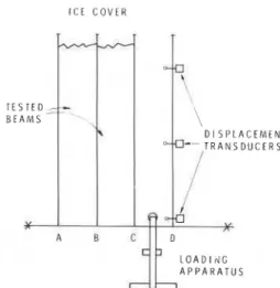
Fig. 2. Schematic of in situ experimental procedure.
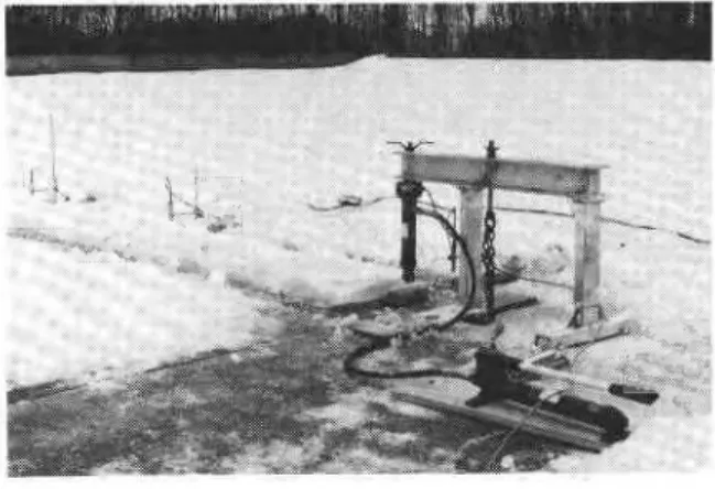
ture conditions it was removed along cutting paths only. The experimental set-up and a schematic of the beam preparation are shown on Figs. 1 and 2, respec-
tively. First a 10-m base line X-X was cut by a chain
saw. Perpendicular to this line, cuts A, B, C, etc.,
were made as successive cantilever beams were tested. In all, three tests were carried out on 0.8-m wide, 4-m long beams, one on an 8-m long 0.8-m wide beam, and one on a 2-m by 2-m cantilever plate. The beams were loaded downward with a concentrated force at the tip by a loading apparatus anchored to the ice cover (Fig. 2). Creep effects were minimized by loading times in the range of 1 to 3 s. Loading was monotonic, but because a hand-operated hydraulic pump was used actual load application was incre- mental.
MATHEMATICAL MODEL
As the problem requires flexibility in specifying geometry and boundary conditions the finite element method was selected. The theoretical background for the computer program has been given by Svec and McNeice (1972) and only a brief description is given below.
I
PlateTwo conforming, triangular-plate bending ele- ments based on polynomials of fifth and seventh
degrees (Fig. 3) are used in the program: (a) an ele- ment with three nodal points at the triangle vortices
with six degrees of freedom in each - a vertical dis-
placement, slopes and curvatures; and (b) an element with ten nodal points and 33 degrees of freedom, as
shown in Fig. 3. The latter has been specifically
developed for contact problems (Svec and Gladwell 1973). Most of the results have been obtained by the first element, i.e., a triangle with three nodal points and 18 degrees of freedom. The global structural stiff- ness matrix is symmetric and banded so that only half of the band is stored. There are two options regarding the solver: (a) half of the band is further divided and stored in submatrices for reduction of core require- ment, or (b) half of the band is stored column-wise in a one-dimensional vector.
Fig. 3. Triangular plate bending elements.
Another convenient feature of the program is an option by which deflection, slopes, curvatures and moments of the plate can be computed over the internal mesh of an element. The density of the internal mesh is specified by only one parameter; it can change from element to element; it can be applied to only selected elements; and it is generated automatically.
BUOYANCY EFFECT
formulation, the plate is considered to rest on an elastic foundation characterized by
where k is the foundation modulus or, for buoyantly supported structures, weight density of the water. There are basically two ways of calculating the buoyancy stiffness matrix. The first assumes that the pressure due to buoyancy is uniformly distributed around each nodal point leading to a step function. The problem associated with this formulation is that the equivalent area of a uniform pressure is some- times difficult to determine. This formulation results in a simple diagonal buoyancy matrix. The second approach, also adopted in this work, assumes that water pressure can be represented by linear or cubic polynomials for the triangular element with three or ten nodes, respectively. Equation (3) shows that this is also equivalent to representing w(x,y) by a poly- nomial, so that
The coefficient vector A can be expressed in terms of the nodal displacements
Equating the work of the nodal forces to the work of the continuous pressure leads to the following buoyancy matrix formulation
W ~ F = JP(x,y) w(x,y) cbl= k Jw2(xy) dA
A A
= ~ A ~ N A = k w T r T N ~ - l w (4) = k w T ~ w
or
F = k N w
The element buoyancy matrices N can then be as- sembled by the usual finite element procedure. The over-all stiffness equations for the plate resting on an elastic foundation is
RESULTS A N D DISCUSSION
The finite element (FE) computer program was validated by analysing a rectangular plate simply supported along its edges and loaded by a concen- trated force at its centre. Computations were per- formed for several plate length-to-width ratios, as shown in Table 1. It is known that very slender ele- ments with high length-to-width ratios (in this case larger than -3) are considerably stiffer (Table 1). In addition, examples of a few free-cantilever and floating or buoyantly supported beams were analysed numerically to establish the influence of various boundary and loading conditions. Because of sym- TABLE 1
or = wD/Pa2
Lengthlwidth Element9 , Closed form 3 Nodes . 1 0 Nodes
18 D.O.F. ' 33 D.O.F.
metry, half of the beam was approximated by a set of finite elements (Figs. 4a). The results are sum- marized in Table 2. As k is weight density, its value of 0 or 10 kN/m3 represents either a free (unsupported) cantilever or a floating beam, respectively.
It was the purpose of the first run to approach simple, free-cantilever beam conditions as closely as possible. Beain width (in this case 0.4 m) was taken as half the beam width used in the field experiments. Loads were applied at the centre and at the edges of the beam to simulate actual loading and the slopes across it were set to zero, GX = 0. The influence of doubling beam width is shown in the second line of Table 2, where a slight departure from previous results demonstrates the plate effect. In the next run (No. 3) the applied load was simulated by a concen- trated force at the centre only, along with the boun- dary conditions required by symmetry. These condi- tions yielded a more flexible system. The fourth
BEAM P L A T E
( a ) ~ b )
Fig. 4 . Finite element mesh for beam and beam plate models.
example shows the effect of buoyant support. The last two results, runs 5 and 6, were obtained by using a model that included the surrounding plate, taking into account the flexibility of the end support
(Fig. 4b). If the plate is simply supported along the edges, the difference in deflection under the load
(x = y = 0) compared with that of a cantilever beam is
a remarkable 24.2%. For a floating plate, still simply supported along the edges, the difference decreases to 16.1%. A finite free floating plate can yield a substan- tial difference. This clearly demonstrates the impor- tance of proper boundary and supporting conditions for analyses.
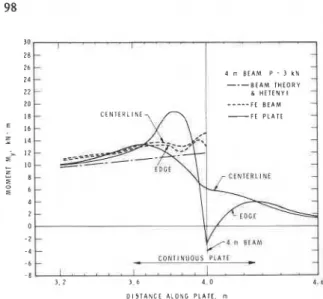
One of the more interesting results of these computations was in bending moment distribution. Moment,
M y ,
is shown in Fig. 5 for a cantilever beam versus a beam attached to the floating plate in the small region around the beam root. This calculation is performed in selected elements by interpolating dis- placement polynomials at all points of an automat- ically generated internal mesh and evaluating all curvatures and moments. Broken lines represent the 4-m cantilever beam with a clamped end, and de- scribe moment,M y ,
along the beam line of symmetry and its edge. The oscillations in moment,M y ,
are mainly caused by the high stress concentration in the built-in edge. The second derivative of the displace- ment function is not continuous across elementTABLE 2
Program validation, cantilever beam
I = 4 m, P = 30 kN, y = 0, Point 1(0,0), Point 2(b/2,0)
Run k b Point P B.C. FE plate Beam-exact A (%)
No. (kN/m3) (m) (kN)
w
@y l o - =w,aY
10-(mm) (mm)
1 0 0.4 7.5 bX = 0 4.88 0.183 w = 5.00 -2.4
4 m B E A M P 3 k N
B E A M T H E O R Y & H E T E N Y I --- F C B E A M
D I S T A N C E A L O N G P L A T E , rn
Fig. 5 . Moment My distribution for 4-m beam.
boundaries, which also contribute to this effect (see for example the centreline moment at 3.6 m). The higher moment along the centreline is caused by two- dimensional plate effects. The solid lines in Fig. 5 are for the cantilever attached to a floating plate (Fig. 4b) and represent MY distribution, again along the line of symmetry and the edge. The moment along the edge peaks somewhat in front of the end of the cut (beam root), then reaches a nega- tive value due to a singularity of the stress at the root. ,
Similarly, the centerline moment has a maximum in front of the beam root. This coincides well with ex- perimental observations, which showed that the tested beams often broke 10 to 20 cm away from the root. It should be pointed out that the results presented were obtained using a plate bending element based on Kirchhoffs thin plate theory. The stress distribution in the root area, however, is clearly three dimensional. Therefore the moment peaks should only be considered in a qualitative sense at this stage. A more detailed examination of the three dimensional stress field at the root of the beam will be the subject of future analysis.
Another important fact associated with moment distribution in the area of the beam root is the deter- mination of flexural strength o f , which is usually calculated from simple beam theory using
It is clear from Fig. 5 that the difference between the calculated strength in bending for the cantilever beam
and that of the beam attached to the continuous plate can be significant. The results from the Hetenyi closed-form solution are almost identical to those from cantilever beam theory owing to the relatively small length-to-thickness ratio of the beams (4 m). The moment distribution around the root of the beam very much depends on beam length, a fact that is demonstrated in Fig. 6, which shows results for an 8-m beam. The moment peaks again in front of the root, but in this case the maximum for all solution methods is the same. A secondary peak develops behind the root in the connected plate. The curves for the central line and for the edge are now much closer together as plate effect is damped. It seems that the stress concentration along the root and the sign reversal of its singularity at the end of the cut could perhaps justify more detailed investigation as will be discussed in the conclusions of this paper. The second objective of this paper was to compare the results of full-size in situ experiments with those
, C E N T E R L I A E 8 m B E A M P = 1 k N B E A M T H E O R Y H E T E N Y I .... FE B E A M D I S T A N C E A L O N G P L A T E m 2
Fig. 6 . Moment My distribution for 8-m beam. 8 n B E A M
-
- -
C C N T I N U O U S P L A T E
-
Cobtained by the finite element method. In all the com- putations presented, Young's moduli and Poisson's ratios were estimated to be 6.0 GPa and 0.3, respec- tively (Sinha 1979). These estimates were sufficiently accurate to make additional investigation of the values of these properties unnecessary.
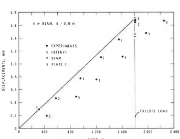
The first set of experiments was performed on 4-m long, 0.8-m wide cantilever beams (Fig. 7). There was good agreement between the results of the first two tests; the third test is offset, but does have a similar slope. This could be due to measuring and recording inaccuracies at small displacements or to reaction of
- d - I I I
4 m BEAM. B ,= 0.8 m
EXPERIMENTS
0 HETENYI BEAM
Fig. 7. Comparison of numerical and experimental analyses of 4-m beam, beam tip displacement.
D I S T A N C E A L O N G B E A M , m
-
I I'
I- HETENYI L DM N FI, h' . O . E h, lOOO N ',, A, h~ = 0.82 h. 1 M O N,
0-0 E X P E R I M E N T S , I M O N 0 - - - 0 H E T E N Y 1 FE B E A M I 6 F E B E A M , h ' = R E D U C E D h FL h' = 0.80 h, I DM N 18Fig. 8. Comparison of numerical and experimental analyses of 8-m beam, beam deflection.
1 4
1
' r n M s D u c E n i I I P L A T E 2 m x 2 m r r s ra
a
@1
TRANSOUCERS 0 I , I 1 , I . I I 0 2 0 0 0 4 0 0 0 6 0 0 0 11 000 10 000 LOAD. NFig. 9. Experimental and numerical results of 2 by 2 m canti- lever plate.
the beam to the incremental loading. Ignoring the off- set, the slope of all tests is in good agreement. Also shown on Fig. 7 are the predictions using Hetinyi's beam theory, i.e. clamped beam and the FE method. This demonstrates that the finite element method, taking into account the effect of the ice cover to which the beam is attached, leads to a better repre- sentation of the behaviour of an ice beam.
Comparison of the 8-m ice beam test results with those obtained by analytical (Hetenyi) and numerical (finite element) techniques indicates a large discrep- ancy (Fig. 8). As the comparison of 4-m beams and 2 X 2 m plate results show very good agreement, it was concluded that the ice of the 8-m beam had surface cracks. The high sensitivity of over-all beam deflection to crack depth is shown in Fig. 8 ; this parametric study was performed by simply changing plate thickness in elements close to the root. If the ice thickness was effectively reduced by about 70 mm (18%) by cracking, agreement with experimental results would be satisfactory.
The comparison of experimental and finite ele- ment analyses of a cantilever 2 X 2 m plate is pre- sented in Fig. 9. Experimental results of displace- ments in three locations for three tests on the same plate are shown. Good reproducibility and agree- ment with numerical analysis was obtained. Moment distributions for a cantilever plate and one attached to the continuous ice cbver were also evaluated. Distributions were simila( t o those for beams. The maximum moment for tHe plate, however, was less than half that for the bean, a substantial difference.
CONCLUSIONS
The analyses of in situ, cantilever, ice beam test results, using a simple beam theory or Hetenyi closed- form solution for a beam on elastic foundation, can lead to substantial error, due, in part, to the assumed boundary conditions. The analysis of short beams, particularly (less than 5 to 6 m), should use plate theory and include the ice cover t o which the beam is attached.
In most actual problerns such as ice-ship and ice- structure interactions, ice ride-up and pile-up on artificial islands, the ice acts in the form of plates and almost never in the form of beams. The ice cover bending properties should therefore be determined
by in situ plate tests as opposed to beam tests. This, however, presents technical problems because the loading forces need t o be greater.
Testing with simple beams rather than cantilevers would eliminate many problems of analysis and interpretation. As the cantilever beam test offers sig- nificant advantages in test preparation and execution in the field, efforts to improve its interpretation are desirable.
The bending moments calculated from test results on ice cantilever'beams are frequently used t o deter- mine the flexural strength of ice. It has already been shown, however, that the bending moments at the root of a cantilever ice beam could be significantly different from calculated moments using closed form beam solutions. This is especially true for shorter
beams (I/b <-4, h
=
0.5 b) where two-dimensionalplate behaviour comes into effect. Furthermore, the stress concentrations, singularities, and perhaps even the three-dimensional nature of the stress distribu- tion at the beam root (end of the cut) makes the problem more complicated. Since these problems came to light during this present work, the authors will discuss them in a subsequent paper. This will include further experimental results and analysis of the three-dimensional stress field at the root of the beam.
The effect of other assumptions used in this paper should also be investigated; for example, the influ- ence of thickness using Reissner's (1945) thick plate theory can be incorporated into the present finite element program. Another area for study would include assessing the effect of temperature change across ice thickness. The experimental procedure can be improved by using a more precise automatic loading apparatus, with a larger number of displace- ment transducers.
ACKNOWLEDGMENTS
This paper is a contribution from the Division of Building Research, National Research Council of Canada, and is published with the approval of the Director of the Division.
NOTATION
square plate dimension area of element
vector of polynomial coefficient beam width
Eh3/12 (1 - v2), plate rigidity
Young's modulus vector of external forces gravitational acceleration plate thickness
moment of inertia
subgrade modulus (weight density = pg)
plate stiffness matrix [ l , x , y , x 2 , x y , y 2 ] vector beam length
bending moment
foundation stiffness matrix
contact pressure between plate and founda- tion
concentrated load
matrix obtained by evaluating w(x, y ) in nodal points) cartesian coordinates I - x deflection function displacement vector P water density (Y w ~ / P a ~ of flexural strength
@ slope of deformed beam or plate
h (k/4El) 'I4
v Poisson's ratio
REFERENCES
Frankenstein, G.E. (1970), The flexural strength of sea ice as determined from salinity and temperature profiles, National Research Council of Canada, Associate Commit- tee on Geotechnical Research, TM 98, pp. 66-73. Frederking, R. and Hausler, F.-U. (1978), The flexural behav-
iour of ice from in situ cantilever beam tests, IAHR Symposium on Ice Problems, Lulei, Sweden, Part 1, pp. 197-215.
Hetgnyi, M. (1946), Beams on elastic foundation, University o f Michigan, Scientific Series, Vol. XVI.
Kerr, A.D. and Palmer, W.T. (1972), The deformation and stresses in floating ice plates, Acta Mechanica, 15: 57-72.
Maattinen, M. (1975), On the flexural strength of brackish water ice by in situ tests, Proceedings, Third International Conference on Port and Ocean Engineering under Arctic Conditions, Fairbanks, pp. 349-359.
Michel, B. and Ramseier, R.O. (1972), Classification of river and lake ice, Can. Geotech. J., 8: 35-45.
Reissner, E. (1945), On the effect of transverse shear de- formation on the bending of elastic plates. J. Applied Mechanics, 12: A69-A77.
Sinha, N.K. (1979), Grain-size influence on effective modulus of ice, Proceedings, Workshop on Bearing Capacity of Ice Covers, Winnipeg, Man., National Research Council of
Svec, O.J. and Gladwell, G.M.L. (1973), A triangular plate bending element for contact problems, Int. J. of Solids and Structures, 9: 435-446.
Svec, O.J. and McNeice, G.M. (1972), Finite element analysis of finite sized plates bonded to an elastic half space, Com- puter Methods in Applied Mechanics and Engineering,
l(3): 265-277.
Vaudrey, K.D. (1977), Determination of mechanical sea ice properties by large-scale field beam tests, Fourth Inter- national Conference on Port and Ocean Engineering under Arctic Conditions, St. John's, Newfoundland, Vol. 1, pp. 529-543.
Canada, Associate Committee on Geotechnical Research, TM 123, pp. 65-77.
T h i s publication i s being d i s t r i b u t e d by t h e Division of Building R e s e a r c h of t h e National R e s e a r c h C o u . ~ r i l of Canada. I t should not b e r e p r o d u c e d i n whole or in p a r t without permission of the o r i g i n a l p u b l i s h e r . T h e Di- v i s i o n would b e glad t o be of a s s i s t a n c e i n obtaining s u c h p e r m i s s i o n .
P u b l i c a t i o n s of t h e Division m a y b e obtained by m a i l - ing the a p p r o p r i a t e r e m i t t a n c e ( a Bank, E x p r e s s , o r P o s t Office Money O r d e r , o r a cheque, m a d e p a y a b l e t o t h e R e c e i v e r G e n e r a l of Canada, c r e d i t NRC) t o t h e National R e s e a r c h Council of Canada, Ottawa. K1A 0R6. S t a m p s a r e n o t a c c e p t a b l e .
A l i s t of a l l publications of the Division i s a v a i l a b l e a n d m a y b e obtained f r o m the P u b l i c a t i o n s Section, Division of Building R e s e a r c h , National R e s e a r c h Council of Canada. Ottawa. KIA OR 6.