Publisher’s version / Version de l'éditeur:
Vous avez des questions? Nous pouvons vous aider. Pour communiquer directement avec un auteur, consultez la
première page de la revue dans laquelle son article a été publié afin de trouver ses coordonnées. Si vous n’arrivez pas à les repérer, communiquez avec nous à [email protected].
Questions? Contact the NRC Publications Archive team at
[email protected]. If you wish to email the authors directly, please see the first page of the publication for their contact information.
https://publications-cnrc.canada.ca/fra/droits
L’accès à ce site Web et l’utilisation de son contenu sont assujettis aux conditions présentées dans le site LISEZ CES CONDITIONS ATTENTIVEMENT AVANT D’UTILISER CE SITE WEB.
Technical Note (National Research Council of Canada. Division of Building
Research), 1974-05
READ THESE TERMS AND CONDITIONS CAREFULLY BEFORE USING THIS WEBSITE.
https://nrc-publications.canada.ca/eng/copyright
NRC Publications Archive Record / Notice des Archives des publications du CNRC : https://nrc-publications.canada.ca/eng/view/object/?id=371927ef-319c-48fc-accd-f310354e6873 https://publications-cnrc.canada.ca/fra/voir/objet/?id=371927ef-319c-48fc-accd-f310354e6873
NRC Publications Archive
Archives des publications du CNRC
This publication could be one of several versions: author’s original, accepted manuscript or the publisher’s version. / La version de cette publication peut être l’une des suivantes : la version prépublication de l’auteur, la version acceptée du manuscrit ou la version de l’éditeur.
For the publisher’s version, please access the DOI link below./ Pour consulter la version de l’éditeur, utilisez le lien DOI ci-dessous.
https://doi.org/10.4224/40001192
Access and use of this website and the material on it are subject to the Terms and Conditions set forth at
Vibration measurements to aid in the design of optical microscope
isolation systems
NATIONAL RESEARCH COUNCIL OF CANADA
DIVISION OF BUILDING RESEARCH
No.
584 PREPARED BYNOT
G. Pernica II.- ,; .r
OJ. "I
.t CHECKED BYo
T.D.N. APPROVED BY A.G.W. PREPARED FOR SUBJECT DATE May 1974 Record Purpose sVIBRATION MEASUREMENTS TO AID IN THE DESIGN OF OPTICAL MICROSCOPE ISOLATION SYSTEMS
LOCATION AND DESCRIPTION OF INSTRUMENTS
On 23 January 1974 the Documentation Section of the Canadian Conservation Institute requested that vibration measurements be taken in seve ra1 of their office s in the Bankal Building, a four - storey office building at the corner of Bank and Albert Streets in downtown Ottawa. The Docurnentation Section had recently been formed and was housed in quarters on the second floor of this building. Many of the Section's new optical microscopes had temporarily been placed in Room 114. They were to be moved shortly to more permanent positions in Room 102 (Figure 1). Rooms 102 and 114 contained wall-to-wall carpeting as did most of the other offices on the second floor. Room 114 was located at the northeast corner of the Bankal Building and overlooked Bank Street, a north-south arterial road that had been narrowed to two lanes in エィHセ
downtown core area to reduce its traffic capacity. Room 102 was situated near the southeast corner and overlooked a construction site just to the we st of the Bankal Building. At this time excavation of the foundation for a large building was in progress. As a result, a great deal of large noisy construction equipment, such as compressors, generators, bUlldozers and shovels, was on the site and in full operation. Blasting was also soon to start and was to last for approximately two months. This difference in the exterior building environment of the two office s
prompted the request for the vibration measurements. Because traffic on Bank Street had at time s affected the satisfactory operation of some of the microscopes in Room 114, it was felt that Room 102 would be
Nセ
-Z-even less suitable as a ITlicroscope rOOITl unless isolation systeITls were provided. This feeling was justified upon entering the rOOITls. In contrast to ROOITl 114, ROOITl 10Z contained a high level of background noise and the floor vibrated at a perceptible level.
Included aITlong the ITlicroscope s in ROOITl 114 we re a Leitz Orthoplan Microscope with ultraviolet laITlping and a Reichert Metallurgical
Microscope. The Leitz ITlicroscope had been placed on a 5- x Z l/Z-x Z l/Z-ft wooden table. The Reichert ITlicroscope was supported on a
steel table that forITled part of the ITlicroscope unit. Neither the wooden table nor the table portion of the Reichert ITlicroscope had been isolated froITl the floor. The optical portion of the Reichert ITlicroscope, however, had been isolated froITl the support unit by the ITlanufacturer. It was
frequently difficult to obtain sharp clear iITlages with the Leitz ITlicro-scope, thus ITlagnified objects could not be photographed. Although SOITle blurring did occur with the Reichert ITlicroscope, satisfactory photographs were still possible.
FLOOR VIBRATION MEASUREMENTS
It was necessary to know the dOITlinant frequencies and aITlplitudes of the three cOITlponents of floor vibration of ROOITl 10Z in order to de sign isolation systeITls. Vibration ITleasureITlents were taken on the floor of ROOITl 10Z under norITlal office conditions. The output froITl the "Larson" acceleroITleter was first filtered using a ttKron-Hite" filter (50 Hz low pass) and then recorded on a Century strip chart recorder. The results of the ITleasureITlents are sUITlITlarized in Table 1. Vibration ITleasureITlents
were also taken on the floor of ROOITl 114 so that the quantitative difference in vibration levels between the two rOOITlS would be known. The results of these ITleasureITlents are also given in Table 1.
FroITl this Table, it can be seen that: (i) there was very little difference between the two rOOITlS in the lowest dOITlinant frequencies of floor vibration; and (ii) the ITlaxiITlUITl peak-to-peak aITlplitude of accelera-tion of each of the floor cOITlponents of ROOITl 10Z was two to three tiITle s
as large as those in ROOITl 114.
It was recoITlITlended that "fabcel 1 00", "vibron", or a siITlilar rubber ITlaterial be placed under the legs of each ITlicroscope table as an initial atteITlpt to obtain a siITlple, effective, inexpensive isolation systeITl.
EVALUATION OF VIBRATION ISOLATION SYSTEMS
On 11 February vibration ITleasurements were again taken in the Banka1 Building. The Leitz ITlicroscope and the wooden table had been moved to ROOITl 101 where the table had been placed so that its
longi-tudinal axis was north-south in direction (Figure 1). The Reichert micro-scope had been moved to Room 10Z and placed so that its longitudinal axis was east-west in direction. Neither of the tables had been isolated froITl the floor.
-3-(a) Leitz Microscope
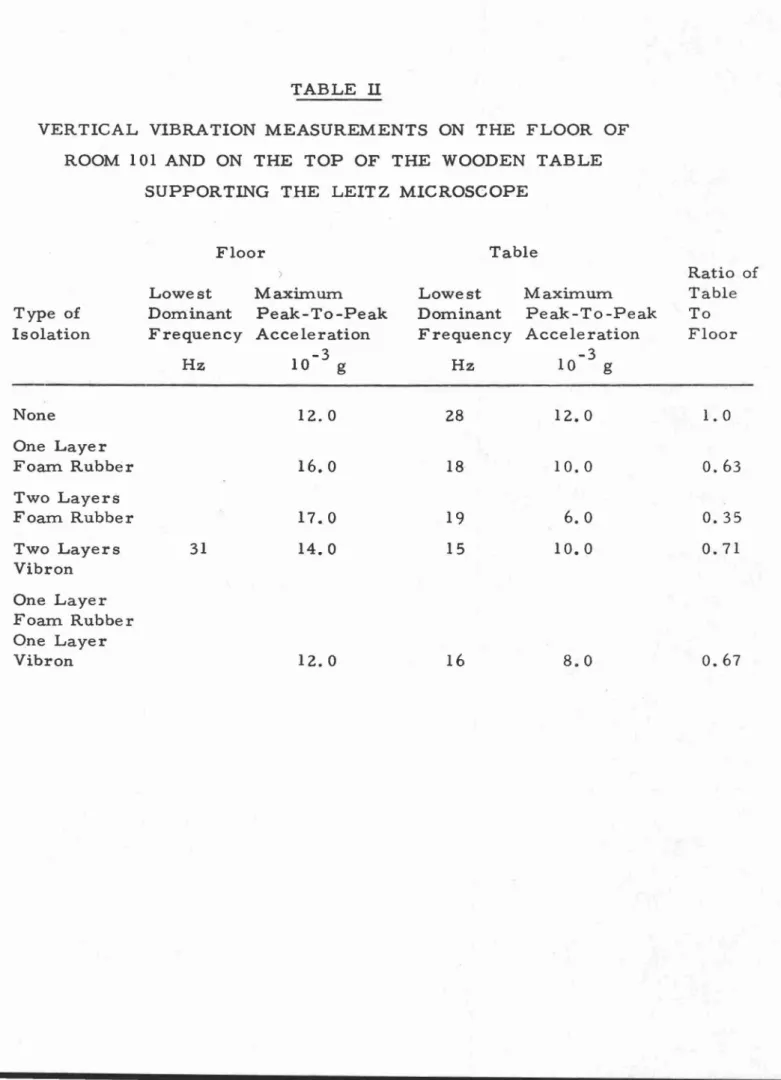
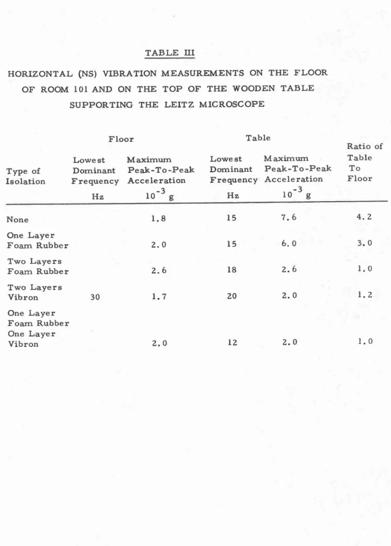
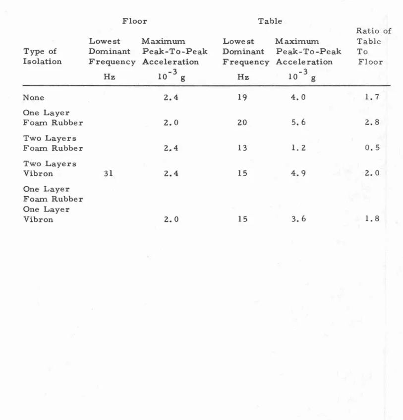
No satisfactory photographs had been obtained in Room 101. In order to isolate the table and thus the microscope, small pads of two rubber materials, vibron and a 3/8-in. thick foam rubber frequently used by the Canadian Conservation Institute as packing material for paintings, were prepared. Various combinations of these pads, were placed under the table legs and for each combination vibration measure-ments were taken simultaneously on the floor and on the table top in
order to determine the system's effectiveness. The results of these measurements are given in Tables II, ill, and IV.
From these Tables it can be seen thattvvo layers of the foam rubber placed under each of the table legs provided the most effective isolation system. As this was the only system that allowed satisfactory photo-graphs to be taken, the following upper bound for the acceleration levels at the top of any table used to support the Leitz microscope was established.
Direction Vertical
Horizontal (Parallel to either table axis)
Lowest Dominant Frequency Hz 31 31 Maximum Peak-to-Peak Acceleration 10- 3 g 7.0 2.0 (b) Reichert Microscope
No difficulty had been experienced with the Reichert microscope in its new location. Vibration measurements were taken in order to record the level of vibration at which the optical portion of the micro-scope operates satisfactorily. The following levels were obtained.
Direction Ve,rtical Horizontal (perpendicular to microscope's longi-tudinal axis) Horizontal (parallel to microscope's longitudinal axis) Lowest Dominant Frequency Hz 30 30 31 Maximum Peak-to-Peak Acceleration 10 -3 g 4.0 3.2
3.6
•
TABLE 1
VIBRATION MEASUREMENTS ON THE FLOOR OF ROOM 102 AND ROOM 114
Floor Room 102 Floor Room 114
Lowest Maximum. Lowest Maximum
Dominant Peak-To-Peak Dominant Peak-To-Peak Frequency Acceleration Frequency Acceleration
Direction Hz 10-3 g Hz 10 -3 g Vertical 30 24.0 35 7.0 Horizontal 30 4.2 30 1.4 NS Horizontal 30 6.4 35 3.0 EW
",
TABLE II
VERTICAL VIBRATION MEASUREMENTS ON THE FLOOR OF ROOM 101 AND ON THE TOP OF THE WOODEN TABLE
SUPPOR TING THE LEIT Z MICROSCOPE
Floor Table
Ratio of
Lowest Maximum. Lowest Maximum. Table
Type of Dominant Peak-To-Peak Dominant Peak-To-Peak To
Isolation Frequency Acceleration Frequency Acceleration Floor
10-3 g -3 Hz Hz 10 g None 12.0 28 12.0 1.0 One Layer Foam Rubber 16.0 18 10.0 0.63 Two Layers Foam Rubber 17.0 19 6.0 0.35 Two Layers 31 14.0 15 10.0 0.71 Vibron One Layer Foam Rubber One Layer Vibron 12.0 16 8.0 0.67
"
TABLE III
HORIZONTAL (NS) VIBRATION MEASUREMENTS ON THE FLOOR OF ROOM 101 AND ON THE TOP OF THE WOODEN TABLE
SUPPORTING THE LEIT Z MICROSCOPE
Floor Table
Ratio of
Lowest Maxim.urn. Lowest Maxim.urn. Table
Type of Dom.inant Peak-To-Peak Dom.inant Peak-To-Peak To Isolation Frequency Acce Ie ration Frequency Acceleration Floor
Hz 10-3 g Hz 10-3 g None 1.8 15 7.6
4.2
One Layer Foam. Rubber 2.0 15 6.0 3.0 Two Layers Foam. Rubber 2.6 18 2.6 1.0 Two Layers Vibron 30 1.7 20 2.0 1.2 One Layer Foam. Rubber One Layer Vibron 2.0 12 2.0 1.0".
TABLE IV
HORIZONTAL (EW) VIBRATION MEASUREMENTS ON THE FLOOR OF ROOM 101 AND ON THE TOP OF THE WOODEN
TABLE SUPPORTING THE LEITZ MICROSCOPE
Floor Table
Ratio of
Lowest Maxi.m.um Lowest Maximum Table
Type of Dominant Peak-To-Peak Dominant Peak-To-Peak To Isolation Frequency Acceleration Frequency Acceleration Floor
Hz 10-3 g Hz 10-3 g None 2.4 19 4.0