3rd International Conference on Bio-Based Building Materials
June 26th - 28th 2019
Belfast, UK
ID_ CCC131
PORE STRUCTURE AND CARBONATION OF HYDRATED LIME MORTAR WITH
MUSSEL SHELL AGGREGATE
C. Martínez-García1; B. González-Fonteboa1*; D. Carro-López1; F. Martínez-Abella1
1School of Civil Engineering. Department of Construction Technology, University of A Coruña.
Postal Address: E.T.S.I. Caminos, Canales, Puertos. Campus Elviña s/n, 15071 La Coruña, Spain.
*Corresponding author; e-mail: bfonteboa@udc.es
Abstract
Galician “Rias” conditions enable the cultivation of excellent quality mussels, as well as extension. This leads Spain to be the third producer country on the world, just after China. The 35% of this production means 25,000 tons of mussel shell waste per year. Hence, it is necessary to find a sustainable use for this material.
The bioconstruction has been recovering the use of air lime mortars for coatings in recent years. Lime is a quite easy available material in most places and its hardening process involves the uptake of CO2 from the atmosphere. Besides the aesthetics of its finishes, the compatibility for its use in the conservation of historic buildings and its proven durability have led to increase the scientific studies with this material.
The purpose of this work is to verify pore structure and carbonation changes of air lime coating mortar when limestone sand is replaced by mussel shell sand. Hydrated commercial lime powder have been used for blended lime pastes. Reference mortar and mortars with mussel shell aggregate as a substitute for limestone aggregate at different rates: 25%, 50% and 75% have been tested. Studies show that mussel shells aggregates increase the pore volume of air lime mortar mixtures, and change their pore size distribution. A low water exchange capacity between the interior of the paste is observed. The use of mussel shell aggregate increase the presence of large pores which guarantees the entry of higher volume of CO2, positively affecting the carbonation degree at one-year age.
Keywords:
Mussel shell; coating mortars; hydrated lime; porosity; carbonation; microstructure
1 INTRODUCTION
Aquaculture is the economic heart of Galicia, as it generates employment and is in constant innovation. Conditions in the Galician “Rias” enable the cultivation of excellent quality mussels, as well as extension: almost 250 thousand tonnes of mussel are produced each year, placing Spain third place in the world behind China [FAO, 2012]. 35% of these mussels are transformed in the cannery industry. This produces large quantities of concentrated residue, approximately 25000 tonnes of mussel shell waste per year [Heinonen, 2014]. Hence, it is of utmost importance to find a sustainable outlet for this material, reduce the environmental impact, and avoid the shells ending up in landfills or being deposited on the seabed.
Literature includes a range of publications where seashell aggregates are used for pastes. For the most part, they study the use of oyster shell sand in cement mortar [Kuo et al., 2013]. Furthermore, there are some works where cockle shells [Motamedi et al., 2015] or a mix of seashells used as aggregate in cement mortar is analysed [Liang and Wang, 2013]. Another study uses
limestone filler obtained from the calcination of mussel shells as a substitute for cement in mortar. However, the number of studies that use seashell aggregates with non-cement binders is scarce and only one study uses bivalve shell sand for coating mortars [Lertwattanaruk et al., 2012].
The use of different bio-waste materials to develop new by-products as well as the use of lime or cement-lime based mortars is a current trend in the construction field [Moretti et al., 2018]. Therefore, in this work, the use of Galician mussel shells as aggregate in air lime coating mortars is analysed.
Building air lime has been used in construction for thousands of years as a binder [Borges et al., 2014]. The Romans used air lime in combination with natural and artificial pozzolans in their buildings. Based on the use of this material, they were able to generate outstanding architectural and urban structures of great beauty and durability. This fact has allowed these complex systems to survive until today, maintaining much of their static, aesthetic, physical and chemical qualities. Two generational changes were enough for the wisdom of thousands of years to be considered
obsolete and the intangible heritage constituted by the knowledge of lime application, would be forgotten.
Fortunately, nowadays due to concern about
environmental deterioration and the principles of sustainability, which are beginning to have a significant impact on the field of architecture, the use of lime has taken on a new dimension, displaying its technical, economic and ecological qualities. Compared with cement-based mortars, lime mortars result in a much more extended setting time, lower compressive strengths and higher porosity, deformability, and water transport characteristics [Lawrence, 2006]. These last four characteristics have proven useful in the field of conservation architecture [‘RILEM TC 203-RHM: Repair mortars for historic masonry’, 2012] and are based on the need to develop compatible new repair materials as identified by the Venice Charter adopted by UNESCO in 1965 [Middendorf et al., 2005a, 2005b].
The purpose of this study was to test the use of mussel shell aggregate in air lime mortars and the effects on their properties. Although it is known that the type of aggregate affects the behaviour of lime mortars
[Scannell et al., 2014], studies that include recycled sand [Stefanidou et al., 2014] or variations of conventional aggregates (limestone and silicate) are scarce in number.
2 MATERIALS AND METHODS 2.1 Binder
In this work a hydrated commercial lime powder (EN 459-1 CL90-S) was used. It is CL 90, with 90% minimum content of calcium and magnesium oxides. The composition of hydrated lime is mainly calcium without any hydraulic or pozzolanic addition. In the FRX analysis (Tab. 1), it can be seen that apart from calcium, they present reduced quantities of magnesium, silicon, aluminate and sulphate, with a residual presence of other oxides. Hydrated lime powder is an air lime produced by slaking quicklime with sufficient water to produce a dry powder. It was received, stored immediately and kept sealed until its use to avoid
contact with atmospheric CO2.
Tab. 5: FRX composition of non-aged lime.
Oxide (%) LOI CaO MgO SiO2 SO3 Al2O3 Fe2O3 K2O SrO CuO MnO ZnO
Non-aged Lime 25.5 72.1 0.59 0.29 0.83 0.11 0.059 0.030 0.043 0.012 0.025 0.009
Lime Putty 22.6 70.5 1.40 0.93 0.41 0.26 0.13 0.042 0.029 0.011 0.005 0.009
LOI: Loss on ignition at 975˚C
2.2 Aggregates
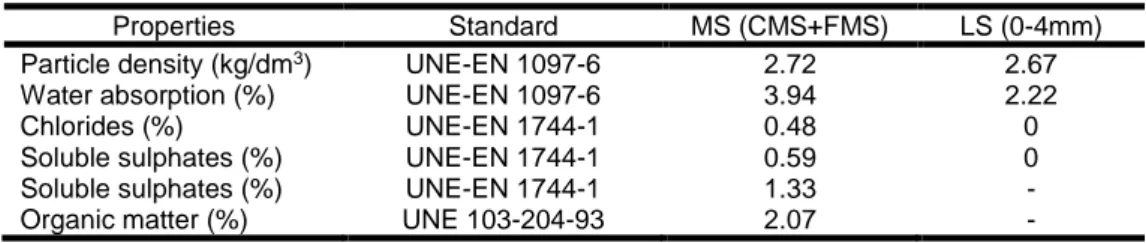
The limestone sand used comes from crushed limestone and it has a maximum size of 4 mm. Since its particle size distribution was not suitable for producing coating mortars, a size separation by sieving was performed (Fig. 1). Then the size fractions were combined, resulting in suitable sand with a maximum size of 2 mm (LS), with a fineness modulus of 2.23. The mussel shell sand used was obtained from a heat treatment (135˚C for 32 min [European Parliament and Council, 2009]). Then it was crushed and sieved. This resulted in two different size fractions: a coarse sand (CMS 0-4mm) and a fine sand (FMS 0-1mm). These two fractions were combined to obtain a mussel shell sand (MS) with an equivalent particle size distribution to the limestone sand (LS), with a fineness modulus of 2.21. Tab. 2 shows the limestone and mussel shell sand properties. The mussel shell presents a small presence of chlorides, soluble sulphates and organic matter, especially the finer fraction.
According to the results of the X-ray diffraction (XRD) characterisation, mussel shells are composed mainly of calcium carbonate (95%). The second compound present is silicon oxide, which has a higher quantity in finer samples of the mussels. Third is the presence of sodium oxide, which can be related to the presence of
sodium chloride in the samples. These results are consistent with those published by other authors [Lertwattanaruk et al., 2012; Yoon et al., 2003; Yoon, 2004].
These shells are formed by the biomineralisation of
CaCO3 with a small amount of organic matrix which
holds the structure together, as was shown in a previous work [Martínez-García et al., 2017].
Fig. 61. Particle size distributionof aggregates used.
Tab. 6: Mussel shell and limestone sand properties.
Properties Standard MS (CMS+FMS) LS (0-4mm)
Particle density (kg/dm3) UNE-EN 1097-6 2.72 2.67
Water absorption (%) UNE-EN 1097-6 3.94 2.22
Chlorides (%) UNE-EN 1744-1 0.48 0
Soluble sulphates (%) UNE-EN 1744-1 0.59 0
Soluble sulphates (%) UNE-EN 1744-1 1.33 -
Organic matter (%) UNE 103-204-93 2.07 -
0 10 20 30 40 50 60 70 80 90 100 0,0625 0,125 0,25 0,5 1 2 4 8 Cu mulativ e per ce ntage pas sin g Particle size (mm) MS (CMS+FMS) NS
2.3 Mortar mixes
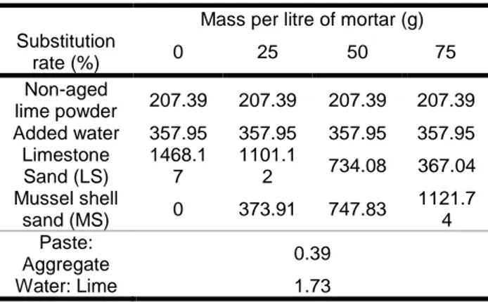
One hydrated lime powder mortar for coating were designed as a reference. This mix was modified replacing, by volume, the limestone sand with mussel shell sand. The substitution rates used were 25%, 50% and 75%. Substitution percentage of 100% was discarded in a preliminary test as the consistency of the mix was too stiff or harsh. Erreur ! Source du renvoi
introuvable. shows the basic mix parameters of every
mortar.
Thus, a water/lime ratio of 1.7 (by volume) was used to design the mortars with non-aged hydrated lime powder.
In accordance to literature [Lanas and Alvarez, 2003] a suitable binder to aggregate ratio could be 1:3 (by volume). However, it is known that mussel shell aggregates increases water demand in mixtures. Thus, in this work the binder/aggregate ratio used for non-aged lime mortars was 1:2.3 (by volume).
As a result, four types of air lime mortars were obtained, four with non-aged lime powder: S0, S25, S50 and S75. Tab. 3 shows the mix proportions by weight of both the reference and mussel shell mortars and also shows paste:aggregate and water:lime ratios used in the mixes.
Tab. 7: Air lime mortars dosages by weight. Mass per litre of mortar (g) Substitution rate (%) 0 25 50 75 Non-aged lime powder 207.39 207.39 207.39 207.39 Added water 357.95 357.95 357.95 357.95 Limestone Sand (LS) 1468.1 7 1101.1 2 734.08 367.04 Mussel shell sand (MS) 0 373.91 747.83 1121.7 4 Paste: Aggregate 0.39 Water: Lime 1.73 2.4 Test methods
Different tests methods were developed and results were analysed. Standard deviation was calculated. Mixing and moulding
After chemical and physical characterization of binders and aggregates, the raw materials were mixed in order to obtain the different mortars.
The mixing procedure was developed according to UNE-EN 196-1: firstly, water and hydrated lime powder were blended for 30 seconds at low speed. Then the aggregate was added and mixed for 30 seconds at low speed and 30 seconds at high speed. The mixing procedure was then stopped for 90 seconds, the mixer walls were scrapped in the first 30 seconds and finally, mixing continued for 60 seconds at high speed. Different batches were made to determine the fresh state and hardened state behaviour of each mortar.
For hardened state tests, mortars were cast in prismatic moulds (40x40x160 mm). The moulding process was done according to UNE-EN 1015-11. Prismatic samples (40x40x160 mm) were used to measure hardened density, carbonation front by phenolphthalein test Microstructure: optical and electronic microscopy Mortar samples were pre-consolidated by impregnation with resin under vacuum. Thin sections were cut and
polished to the thickness of approximately 20 microns, covered with a glass slip and examined with LEICA DM750M optical microscopy. Specimens used for scanning electron microscopy (SEM) were dehydrated and covered with gold in a Bal-Tec SCD 004 sputter coater. Then they were examined and photographed
under a JEOL JSM-6400 Scanning Electron
Microscope.
Porosity, pore distribution and water absorption By means of a core-drill, at least three pieces were taken from different samples of hardened lime mortars at the age of 1 year. They were used to measure water absorption and accessible porosity for water according to UNE 83980. In addition, the pore size distribution was performed with a Mercury Intrusion Porosimetry (MIP), which automatically registers pressure, pore diameter in a range between 0.003 to 200 µm, intrusion volume, and pore surface area. The range of pressure used was 6.29 KPa to 410759.65 KPa.
Carbonation
The carbonation evolution over time was detected by impregnating the mortar samples with a saturated phenolphthalein ethyl alcohol solution. Phenolphthalein is a chemical compound that turns colourless in acidic or near neutral solutions (pH < 8.2). It starts to be visible at pH of about 8.2 and changes colour completely at pH of about 9.8.
Three test samples of each mortar were tested. Each sample of 16x4x4cm was broken at 365 days. After a few seconds, phenolphthalein was sprayed on broken mortar surfaces. Then, photographs were taken to follow-up the evolution of the colouration produced on the surface of the samples treated with phenolphthalein. This follow-up was done a few seconds and several minutes after the spray. This photographic monitoring was carried out to ensure the development of the colouration caused by phenolphthalein in the different lime mortars. Photographic images (Fig. 2) were scanned and digitally analysed using processing software (Image-j), where the percentage of the carbonated surface can be measured on the total area of the treated sample.
Fig. 62: Measurement of the different coloured areas of samples treated with phenolphthalein spray solution, to determine the carbonation development over time in
air lime mortars.
3 RESULTS AND DISCUSSION 3.1 Microstructure
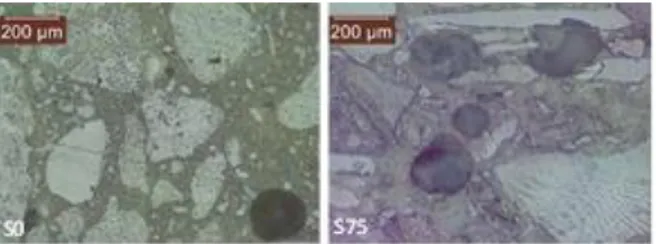
Optical-microscope microphotographs (Fig. 3) and SEM images (Fig. 4) show non-aged hydrated lime mortars with different mussel shell content (0%, 25%, 50% and 75%) at 365 days. The images show the differences in matrix and interfacial transition zone (ITZ) as a function of the mussel shell percentage.
Optical images show coarse pores in lime mortars with high mussel shell content (especially S75). These coarse pores are greater than 100 µm in diameter and usually they are formed by entrapped or entrained air. Entrapped air pores are generated by the entrapment of air during mixing. They present both irregular shape and distribution. On the contrary, entrained air pores are round voids formed by organic materials containing proteins. In this case, air pores shown in the images present both irregular and bubble-like shapes, which means they were produced by entrapped air due to the mussel particle shape, as well as the organic protein present in the mussel shell [Centauro et al., 2017]. Reference mortar hardly show this kind of porosity. Accordingly, SEM images show greater porosity in mussel shell mortars than in reference mortar. Furthermore, with these SEM images the different ITZs can be properly seen.
Mussel aggregate particles are smooth and flat which leads to decreased bonding with the air lime matrix. Hence, clear high porosity is shown in the ITZs of mussel shell mortars. In addition, all mussel mortars present a matrix phase with small cracks in the vicinity of the mussel shells where micro-cracks are formed due to the irregular shape of the aggregate.
Fig. 63 : Optical microscope microphotographies of hydrated lime mortars at 365 days.
Fig. 64 : SEM images of hydrated lime mortars at 365 days: S0 (a) and S75 (b).
3.2 Pore size distribution
Pore size distribution of all mortar was measured with MIP and all analysed samples used in this test (between 0.5-0.8 cm3) showed a very similar total porosity value (25 ± 2%). The pore size distribution is presented in Fig. 5.
As also observed by other authors [Arandigoyen et al., 2005; Arizzi and Cultrone, 2013, 2012] in this work, all mortars showed a bimodal distribution with two peaks, one related to medium sized pores (between 0.1 and 1 µm in diameter-structural peak) and the other to large sized pores (5–30 µm, depending on the mortar type-ITZ peak).
However, the pore size distribution of the mussel shell mortars with high mussel percentages is clearly distinct from that of mortars with low mussel aggregate content. Regarding structural peak, mortars with 75% and 50% mussel shell aggregate present a considerably lower peak value than mortars without mussel shell content or with only 25%. Analysing ITZ peak, it is seen that as the
mussel shell content increases, the percentage of pores between 5 and 40 µm considerably increases.
Finally, mussel shell aggregate content increases the volume of large pores (>50 µm).
Most of the measured pores are between 0.1 and 100 µm, so they are interconnected capillary pores that contribute to water and air transfer through capillary action [Silva et al., 2015]. Sorption pores (<0.1 µm) are gel pores that develop in hydrated phases. In lime-based mortars, pores smaller than 0.1 μm are in limited amounts as they are related to the presence of hydraulic phases as CSH. These pores are formed inside the crystals. Finally coarser pores, above 100 µm, are formed due to entrapped or entrained air as aforementioned.
Small capillary pores (<1 µm) are formed in the binder matrix when water evaporates. Arandigoyen et al. studies that the main peak (0.5-1 µm) varies according to kneading water used in mortar preparation: the more kneading water used the bigger the volume of pores in this peak due to evaporation. As all mussel shell mortars were prepared with the same water as their corresponding baseline mortar, the lower volume of pores in the main peak in these mortars is due to the fact that flaky particles might create a barrier for water evaporation. Therefore, when mussel shell is used at a high percentage, its barrier effect leads to a significant decrease in small capillary pores.
Large capillary pores, sometimes considered as those over 50 µm [Lanas and Alvarez, 2003], sometimes as those over 4-50 µm [Arizzi and Cultrone, 2012] are formed in the spaces between the binder and the aggregate. They occur when the aggregate shape results in bad cohesion between the binder and the aggregate, leading, in addition, to strength reductions. All mussel shell mortars present a higher volume of large capillary pores, which agrees with the microstructure observations that showed a clear high porosity in the ITZs of mussel shell mortars.
Finally, the presence of mussel shell does not affect the sorption pores (<0.1 µm), their quantity being similar regardless of the mussel shell content.
Figure 65. Pore size distribution of hydrated lime mortars.
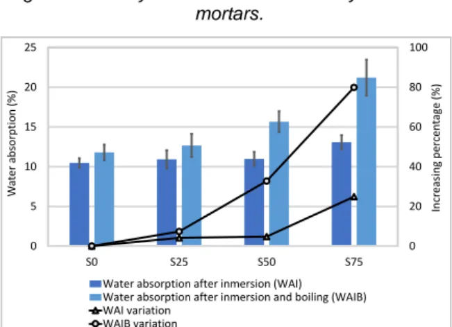
3.3 Open porosity and water absorption
The open water-accessible porosity and the water absorption of all mortars are shown in Fig. 6 and Fig. 7 respectively. Regarding water absorption, both water absorption after immersion, and water absorption after immersion and boiling are shown. As expected, the latter is greater than the former because simple absorption in water does not result in the complete saturation of a porous material as air remains in the
0 0,02 0,04 0,06 0,08 0,1 0,12 0,14 0,001 0,01 0,1 1 10 100 D V /Dlog d (cm 3/g) Pore diameter (µm) S0 S25 S50 S75
pores. Introducing the same saturated samples in boiling water leads to the pore structure being penetrated more fully.
According to these tests, all mussel shell mortars present greater porosity and water absorption than their corresponding baseline mortar. Compared with the reference, S75 show a porosity increment of 20% respectively and water absorption increases again of 21%.
Comparing these results to the ones obtained with MIP (25±2), it is observed that the porosity of mortars with 0% and 25% obtained with MIP, is higher than the porosity measured with water penetration. However, the opposite trend is detected when analysing mortars with 50% and 75% mussel shell. In general, the values of porosity obtained with MIP are higher than those measured with water penetration because higher pressure is used with mercury. Therefore, these mortars show the presence of isolated pores with large radius (exceeding 200 μm) due to air entrainment or entrapment. This pore size radius is not present in the MIP distribution curves and, in addition, as these pores may be isolated mercury cannot enter.
Fig. 66 : Porosity accessible to water of hydrated lime mortars.
Fig. 67 : Water absorption of hydrated lime mortars.
3.4 Carbonation
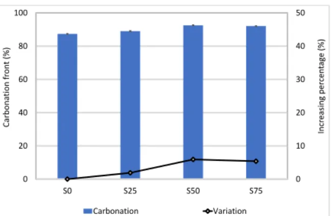
The carbonation front was measured by spraying a freshly broken surface of mortars with phenolphthalein at 365 days (Fig. 8). This coloured area was measured in three samples of each mortar and, using digital analysis, an average value of the percentage of the carbonated area was calculated (Fig. 9).
Fig. 9 shows that at 365 days the mussel shell content increases the carbonation area of air lime mortars. Hydrated lime mortars show increments of 1.9, 5.9 and 5.3%, corresponding to S25, S50 and S75 respectively.
Finally, agreeing with Cazalla et al., hydrated lime mortars present a similar carbonation degree at the age of one year.
The pore structure and the pore water content play an important role in the progress of carbonation in lime
mortars by controlling the rate of CO2 diffusion and the
reactants' dissolution and concentration, as well as the pore solution supersaturation [Cizer et al., 2012a; Mosquera et al., 2002]. In summary, carbonation reaction in lime mortars is only sustained if a free path
exists for CO2 gas to move into the mortar and if water
is present at the same time for the reactants to dissolve [Lawrence, 2006; Mosquera et al., 2002].
Regarding water content, it is well known that the amount of water is critical for the carbonation reaction, as it is needed for dissolution of calcium hydroxide and
CO2, although an excess of water will block the pore
system. In fact, the optimum water content for carbonation is that corresponding to maximum adsorption on the surface of the pores before capillary condensation. To get to this stage, a prior drying process takes place. The drying process presents two phases, a first drying phase that consist of drying at the surface and capillary water transported to the surface, and then a second drying phase that is developed by the diffusion of water to the surface. In the first phase, carbonation hardly exists because carbon dioxide is not allowed to diffuse into the pores [Cizer et al., 2012b, 2012a; Hendrickx et al., 2010].
Therefore, although it is probable that the carbonation rate will be lower in mussel shell mortar than in baseline mortar, at one year of age, the available water content is going to be higher in the former than in the latter. This water content allows carbonation to significantly develop at one year of age and justifies that mussel shell mortars present, at 365 days of age, a higher carbonation area than reference mortars.
Regarding CO2 diffusion, Rodriguez-Navarro [2002]
states that porosimetry plots of carbonated pastes tend to be at the right side of non-carbonated pastes curves, i.e. the pore size and pore volume is greater. Actually, according to Lawrence et al. [2007], pores larger than
10 µm offer the greatest access to atmospheric CO2,
affecting the carbonation process. This trend agrees with the curves shown by the mussel shell mortars. These curves show that mussel shell aggregate increases porosity and redistributes the pore structure (Fig. 5). Air lime mortars with mussel shell aggregate show a greater volume of pores larger than 10 µm,
which allows greater access to the diffusion of CO2.
Therefore, in these mortars atmospheric CO2 easily
penetrates into paste, which again demonstrates their higher carbonation area compared to the area shown by reference mortars. 0 25 50 75 100 0 10 20 30 40 S0 S25 S50 S75 Inc reasi ng per cen tag e (%) Por osi ty (ac cesi ble t o w at er ) (%)
porosity inmersion porosity boiling
Variation porosity after inmersion Variation porosity after boiling
0 20 40 60 80 100 0 5 10 15 20 25 S0 S25 S50 S75 Incr eas ing per cen tag e (%) W at er ab sor p tion (%)
Water absorption after inmersion (WAI) Water absorption after inmersion and boiling (WAIB) WAI variation
Figure 68. Appearance of freshly broken faces of 365 days carbonate hydrated lime mortars samples treated with phenolphthalein at 5 minutes after being sprayed :
a)S0, b)S25, c)S50, d)S75.
Figure 69. Carbonation front of hydrated lime at 365 days.
4 CONCLUSIONS
This work studies the use of mussel shell aggregate as a substitute for limestone sand in coating mortars with hydrated commercial lime powder (S). Different replacement rates of limestone aggregate with mussel shell aggregate (25%, 50% and 75%) were used. Four mixtures were studied, including the reference mortar (without mussel shell): S0, S25, S50 and S75. The results obtained allowed the following conclusions to be drawn:
The mussel aggregates present a particle shape with a high percentage of flaky particles, which leads to a significantly increased water demand and, hence, affects the mortar consistency.
In addition, the mussel shell shape attached to the organic matter content (due to the organic protein, chitin) introduces both irregular and bubble-like voids and changes the pore size distribution in mussel mortar. Firstly, mussel shell aggregate leads mortar to present a higher volume of large capillarity pores (exceeding 50 μm) and also greater isolated pores with large radii (exceeding 200 μm). This leads to increased water absorption in mussel shell mortar. Furthermore, the presence of these large pores guarantees the entry of
higher volume of CO2, which affects the carbonation
degree.
At one-year of age, the available water content is going to be higher in mussel shell mortars. This fact combined
with the entry of a higher volume of CO2 justifies the
higher carbonation degree of mussel mortars at an age of 1 year.
After the results analysis it can be confirm that the replacement percentage of 25% of conventional sand by mussel shell sand leads to obtain a lime based mortar with suitable characteristics to be use as render or plaster. A mussel shell aggregate was obtained with a low environmental process and a low impact binder was used. The use of the mussel coating designed in this work will move construction field towards sustainability.
5 ACKNOWLEDGMENTS
This work has been developed within the framework of the project "Valorización de las conchas de bivalvos gallegos en el ámbito de la construcción" (Valorisation of Galician bivalve shell in the construction sector; Code 00064742 / ITC-20133094), funded by CDTI (Centro para el Desarrollo Tecnológico e Industrial) under the FEDER-Innterconecta Program, and co-financed with European Union ERDF funds. We wish to express our most sincere thanks to the professionals of the firms Extraco, Serumano and Galaicontrol.
6 REFERENCES
[Arandigoyen et al. 2005] Arandigoyen, M., Bernal, J.L.P., López, M.A.B., Alvarez, J.I., 2005. Lime-pastes with different kneading water: Pore structure and capillary porosity. Appl. Surf. Sci. 252, 1449–1459. [Arrizi and Cultrone 2013] Arizzi, A., Cultrone, G., 2013. The influence of aggregate texture, morphology and grading on the carbonation of non-hydraulic (aerial) lime-based mortars. Q. J. Eng. Geol. Hydrogeol. 46, 507–520.
[Arizzi and Cultrone 2012] Arizzi, A., Cultrone, G., 2012. The difference in behaviour between calcitic and dolomitic lime mortars set under dry conditions: The relationship between textural and physical-mechanical properties. Cem. Concr. Res. 42, 818–826.
[Borges et al. 2014] Borges, C., Santos Silva, A., Veiga, M.R., 2014. Durability of ancient lime mortars in humid environment. Constr. Build. Mater. 66, 606–620. [Cazalla et al. 2000] Cazalla, O., Rodriguez-Navarro, C., Sebastian, E., Cultrone, G., De la Torre, M.J., 2000. Aging of lime putty: Effects on traditional lime mortar carbonation. J. Am. Ceram. Soc. 83, 1070–1076. [Centauro et al. 2017] Centauro, I., Cantisani, E., Grandin, C., Salvini, A., Vettori, S., 2017. The influence of natural organic materials on the properties of traditional lime-based mortars. Int. J. Archit. Herit. 11, 670–684.
[Cizer et al. 2012a] Cizer, Ö., Rodriguez-Navarro, C., Ruiz-Agudo, E., Elsen, J., Van Gemert, D., Van Balen, K., 2012. Phase and morphology evolution of calcium carbonate precipitated by carbonation of hydrated lime. J. Mater. Sci. 47, 6151–6165.
[Cizer et al. 2012b] Cizer, Ö., Van Balen, K., Elsen, J., Van Gemert, D., 2012. Real-time investigation of reaction rate and mineral phase modifications of lime carbonation. Constr. Build. Mater. 35, 741–751. [European Parliament and Council 2009] European Parliament and Council, 2009. Regulation (EC) No 1069/2009. Off. J. Eur. Union 300, 1–33.
[FAO 2012] FAO, 2012. The European market for mussels.
[Heinonen 2014] Heinonen, K., 2014. Seafood Watch.
0 10 20 30 40 50 0 20 40 60 80 100 S0 S25 S50 S75 Inc reasi ng per cen tag e (%) Carb on ation fr on t (%) Carbonation Variation
[Hendrickx et al 2010] Hendrickx, R., Roels, S., Van Balen, K., 2010. Measuring the water capacity and transfer properties of fresh mortar. Cem. Concr. Res. 40, 1650–1655.
[Kuo et al. 2013] Kuo, W. Ten, Wang, H.Y., Shu, C.Y., Su, D.S., 2013. Engineering properties of controlled low-strength materials containing waste oyster shells. Constr. Build. Mater. 46, 128–133.
[Lanas and Alvarez 2003] Lanas, J., Alvarez, J.I., 2003. Masonry repair lime-based mortars: Factors affecting the mechanical behavior. Cem. Concr. Res. 33, 1867– 1876.
[Lawrence et al 2007] Lawrence, R.M., Mays, T.J., Rigby, S.P., Walker, P., D’Ayala, D., 2007. Effects of carbonation on the pore structure of non-hydraulic lime mortars. Cem. Concr. Res. 37, 1059–1069.
[Lawrence et al 2006] Lawrence, R.M.H., 2006. A study of carbonation in non-hydraulic lime mortars. PhD Thesis 344.
[Lertwattanaruk et al 2012] Lertwattanaruk, P., Makul, N., Siripattarapravat, C., 2012. Utilization of ground waste seashells in cement mortars for masonry and plastering. J. Environ. Manage. 111, 133–141. [Liang and Wang 2013] Liang, C.F., Wang, H.Y., 2013. Feasibility of pulverized oyster shell as a cementing material. Adv. Mater. Sci. Eng. 2013.
[Martínez-García et al. 2017] Martínez-García, C., González-Fonteboa, B., Martínez-Abella, F., Carro- López, D., 2017. Performance of mussel shell as aggregate in plain concrete. Constr. Build. Mater. 139, 570–583.
[Middendorf et al 2005a] Middendorf, B., Hughes, J.J., Callebaut, K., Baronio, G., Papayianni, I., 2005. Investigative methods for the characterisation of historic mortars---Part 1: Mineralogical characterisation. Mater. Struct. 38, 771–780.
[Middendorf et al 2005b] Middendorf, B., Hughes, J.J., Callebaut, K., Baronio, G., Papayianni, I., 2005. Investigative methods for the characterisation of historic mortars - Part 2: Chemical characterisation. Mater. Des. 38, 771–780.
[Moretti et al 2018] Moretti, J.P., Sales, A., Quarcioni, V.A., Silva, D.C.B., Oliveira, M.C.B., Pinto, N.S., Ramos, L.W.S.L., 2018. Pore size distribution of mortars produced with agroindustrial waste. J. Clean. Prod. 187, 473–484.
[Mosquera et al 2002] Mosquera, M.J., Benítez, D., Perry, S.H., 2002. Pore structure in mortars applied on restoration: Effect on properties relevant to decay of granite buildings. Cem. Concr. Res. 32, 1883–1888. [Motamedi et al 2015] Motamedi, S., Shamshirband, S., Hashim, R., Petković, D., Roy, C., 2015. Estimating unconfined compressive strength of cockle
shell-cement-sand mixtures using soft computing
methodologies. Eng. Struct. 98, 49–58.
[RILEM 2012] RILEM TC 203-RHM: Repair mortars for historic masonry, 2012. . Mater. Struct. 45, 1287–1294. [Rodriguez-Navarro et al 2002] Rodriguez-Navarro, C., Cazalla, O., Elert, K., Sebastian, E., 2002. Liesegang pattern development in carbonating traditional lime mortars. Proc. R. Soc. A Math. Phys. Eng. Sci. 458, 2261–2273.
[Scannell et al 2014] Scannell, S., Lawrence, M., Walker, P., 2014. Impact of aggregate type on air lime mortar properties. Energy Procedia 62, 81–90.
[Silva et al 2015] Silva, B.A., Ferreira Pinto, A.P., Gomes, A., 2015. Natural hydraulic lime versus cement for blended lime mortars for restoration works. Constr. Build. Mater. 94, 346–360.
[Stefanidou et al 2014] Stefanidou, M., Anastasiou, E., Georgiadis Filikas, K., 2014. Recycled sand in lime-based mortars. Waste Manag. 34, 2595–2602. [Yoon et al 2003] Yoon, G., Kim, B., Kim, B., Han, S., 2003. Chemical – mechanical characteristics of crushed oyster-shell. Waste Manag. 23, 825–834.
[Yoon et al 2004] Yoon, H., 2004. Oyster Shell as Substitute for Aggregate in Mortar. Waste Manag. Res. 22, 158–170.