Publisher’s version / Version de l'éditeur:
Vous avez des questions? Nous pouvons vous aider. Pour communiquer directement avec un auteur, consultez la
première page de la revue dans laquelle son article a été publié afin de trouver ses coordonnées. Si vous n’arrivez pas à les repérer, communiquez avec nous à [email protected].
Questions? Contact the NRC Publications Archive team at
[email protected]. If you wish to email the authors directly, please see the first page of the publication for their contact information.
https://publications-cnrc.canada.ca/fra/droits
L’accès à ce site Web et l’utilisation de son contenu sont assujettis aux conditions présentées dans le site LISEZ CES CONDITIONS ATTENTIVEMENT AVANT D’UTILISER CE SITE WEB.
Research Report (National Research Council of Canada. Institute for Research in
Construction), 2005-03-01
READ THESE TERMS AND CONDITIONS CAREFULLY BEFORE USING THIS WEBSITE.
https://nrc-publications.canada.ca/eng/copyright
NRC Publications Archive Record / Notice des Archives des publications du CNRC : https://nrc-publications.canada.ca/eng/view/object/?id=8443fe23-0031-4583-8883-2de65cecafb3 https://publications-cnrc.canada.ca/fra/voir/objet/?id=8443fe23-0031-4583-8883-2de65cecafb3
NRC Publications Archive
Archives des publications du CNRC
For the publisher’s version, please access the DOI link below./ Pour consulter la version de l’éditeur, utilisez le lien DOI ci-dessous.
https://doi.org/10.4224/20378337
Access and use of this website and the material on it are subject to the Terms and Conditions set forth at
Fire Endurance Experiments on FRP-Strengthened Reinforced
Concrete Slabs and Beams-Slab Assemblies
Fire Endurance Experiments on FRP-Strengthened Reinforced
Concrete Slabs and Beam-Slabs Assemblies
by
V.R.K. Kodur, B.K. Williams, M.F. Green and L.A. Bisby
Research Report No. 175
March 2005
Fire Research Program
Institute for Research in Construction
National Research Council Canada
FIRE ENDURANCE EXPERIMENTS ON FRP-STRENGTHENED REINFORCED CONCRETE SLABS AND BEAM-SLAB ASSEMBLIES
By
V.K.R. Kodur, B. Williams, M. Green and L. Bisby
ABSTRACT
Fire resistance experiments were conducted at the National Research Council of Canada (NRC) in partnership with Intelligent Sensing for Innovative Structures (ISIS) Canada and Fyfe Co. LLC, to investigate the behaviour of FRP-strengthened reinforced concrete slabs and beam-slab assemblies under exposure to a standard fire. The slabs and beams were provided with a unique supplemental fire protection system. The results of fire endurance experiments on two full-scale FRP-strengthened reinforced beam-slab assemblies and two intermediate-scale FRP-strengthened reinforced concrete slabs are described in this report. These experiments were conducted as part of a collaborative research program aimed at studying fire endurance of reinforced concrete members strengthened with externally-bonded FRP systems. The results suggest that by providing proper supplemental fire insulation, as described in this report, fire endurance ratings of up to four hours can be achieved for loaded FRP-strengthened reinforced concrete beam-slab assemblies.
FIRE ENDURANCE EXPERIMENTS ON FRP-STRENGTHENED REINFORCED CONCRETE SLABS AND BEAM-SLAB ASSEMBLIES
By
V.K.R. Kodur, B. Williams, M. Green and L. Bisby
ACKNOWLEDGMENTS
The authors are members of the Intelligent Sensing for Innovative Structures Network (ISIS Canada) and wish to acknowledge the support of the Networks of Centres of Excellence Program of the Government of Canada and the Natural Sciences and Engineering Research Council. The authors would also like to acknowledge the National Research Council of Canada, Fyfe Co. LLC, and Watson Bowman Acme Corp. Finally, the authors wish to thank the following people for their assistance: Paul Thrasher, Neil Porter, Dave Tryon, John Latour, Joe Hum, Patrice Leroux, Jocelyn Henrie and Roch Monette.
FIRE ENDURANCE EXPERIMENTS ON FRP-STRENGTHENED REINFORCED CONCRETE SLABS AND BEAM-SLAB ASSEMBLIES
By
V.K.R. Kodur, B. Williams, M. Green and L. Bisby
INTRODUCTION
In recent years, the construction industry has shown significant interest in the use of FRP materials for reinforcement and strengthening of concrete structures. This interest can be attributed to the numerous advantages that FRP materials offer over conventional materials. One particularly successful use of FRPs in structural engineering applications involves repair and rehabilitation of existing reinforced concrete structures by bonding the FRP strengthening system to the exterior of reinforced concrete members.
In buildings, FRP strengthened structural system members must be designed to satisfy the requirements of serviceability and safety limit states. One of the major safety requirements in building design is the provision of appropriate fire safety measures for structural members [1, 2]. The basis for this requirement can be attributed to the fact that, when other measures for containing the fire fail, structural integrity is the last line of defence for building occupants.
With the increased use of FRP, concern has developed regarding their behaviour in fire, since FRP materials are known to be susceptible to deterioration at elevated temperatures. Before FRP reinforcement can be used with confidence in buildings, the performance of these materials during fire, and their ability to meet the fire endurance criteria set out in building codes, must be evaluated. To date, information in this area is extremely scarce, and a great deal of further work is required to fill all the gaps in knowledge.
Studies are in progress at the National Research Council of Canada (NRC), in collaboration with ISIS Canada, Queen's University, Fyfe Co. LLC, and Watson Bowman Acme, to develop fire resistance design guidelines for FRP-strengthened concrete systems for possible incorporation into codes and standards [2, 3, 4]. As part of this effort, fire endurance experiments were carried out on two full-scale FRP-strengthened reinforced concrete beam-slab assemblies and two mini FRP-strengthened reinforced concrete slabs. The results of these experiments are presented in this report. The main objective of the experiments was to investigate the behaviour of FRP-strengthened reinforced concrete slabs and beam-slab assemblies under exposure to the standard fire.
TEST SPECIMENS
The experimental program consisted of fire endurance tests on two reinforced concrete slabs and two reinforced concrete beam-slab assemblies strengthened with the Tyfo® SCH carbon/epoxy FRP
system∗. The beam-slab assemblies were T-shaped in cross-section and were designated as Beam 1 and
Beam 2. The mini slab assemblies were designated as Slab 1 and Slab 2. Details of the test program are given in Table 1.
The slabs were tested solely to evaluate the thermal effectiveness of the strengthening/insulation system. As such, no load was applied to these specimens. The beams were tested to evaluate the overall effectiveness of the strengthening/insulation system under fire exposure and load.
∗ Certain commercial products are identified in this paper in order to adequately specify the experimental procedure.
In no case does such identification imply recommendations or endorsement by the National Research Council, nor does it imply that the product or material identified is the best available for the purpose.
Dimensions
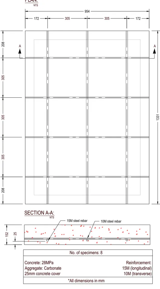
The slabs were rectangular in shape, 1331 mm (52.4 in.) by 954 mm (37.6 in.), and 150 mm (6 in.) thick. The reinforcement details of the slabs are provided in Figure 1.
The beams were 3.8 m (12.5 feet) in span, and had a T-shaped cross-section. The flange was 150 mm (6 in.) thick, and 1220 mm (48 in.) wide. The web of the section was 250 mm (10 in.) deep, and 300 mm (11.8 in.) wide. The reinforcement details of the slabs are provided in Figure 2.
Materials
Cement
Type I Portland cement, a general purpose cement for construction of reinforced concrete structures, was used for constructing the reinforced concrete slabs and beam-slab assemblies.
Aggregates
The beams and slabs were fabricated with carbonate aggregate concrete. When concrete is made with coarse aggregate consisting mainly of calcium carbonate or a combination of calcium and magnesium carbonate (for example limestone and dolomite), it is referred to as carbonate aggregate concrete. The maximum aggregate size used in the slabs and beams was 14 mm [0.55 in] and 16 mm [0.63 in], respectively. The fine aggregate used was natural sand.
Reinforcement
Deformed bars were used for both main longitudinal bars and ties. In the slabs, all reinforcement had a specified yield strength of 400 MPa (58 ksi). In the beams, all 10M bars had a specified yield strength of 400 MPa (58 ksi), while the 20M bars had a specified yield strength of 500 MPa (73ksi).
The longitudinal reinforcement in the slabs in the 1331 mm (52.4 in.) direction was three 15M (5/8 in.) bars, with 25 mm (1 in.) clear cover to the reinforcement from the bottom. The longitudinal reinforcement in the slabs in the 954 mm (37.6 in.) direction was four 10M (3/8 in.) bars, supported by the 15M bars below. The reinforcing bars were tied together at their junction points with steel ties. Details are provided in Figure 1.
Longitudinal reinforcement in the beams consisted of two 15M (5/8 in.) bars located in the base of the beam web. Additional longitudinal reinforcement in the beams consisted of eight 10M (3/8 in.) bars located 50 mm (2 in.) from the top of the flange, and six 10M (3/8 in.) bars located 50 mm (2 in.) from the base of the flange.
Lateral reinforcement in the beams consisted of 10M (3/8 in.) ties located at 40 mm (1.6 in.) from the concrete exterior, and spaced at 150 mm (6 in.) o/c. Additional lateral reinforcement was provided in the flange in the form of two 10M (3/8 in.) bars, each located 40 mm (1.6 in.) from the concrete face, and spanning across the flange, spaced at 150 mm (6 in.) o/c along the beam span. The location and layout of reinforcement in the beams is provided in Figure 2.
A single batch of concrete was used for fabricating the slabs. The concrete was supplied by Lafarge Ready-Mix, Kingston, Canada, and was delivered to Queen’s University. The concrete specifications called for non air-entrained concrete with a 28-day compressive strength of 28 MPa (4100 psi).
Two different batches of concrete were used for fabricating the beams. The concrete was supplied by PreCon in Belleville, Canada. The concrete specifications called for non air-entrained concrete with a 28-day compressive strength of 41 MPa (6000 psi).
Batch quantities and measured properties of the concrete mixes are given in Table 2. The 28-day cylinder compressive strength of the slab concrete was 32 MPa (4645 psi), and the corresponding compressive strength on the day of the slab fire endurance tests was 28 MPa (4064 psi). The 28-day cylinder compressive strength of the beam concrete was on average 52 MPa (7547 psi), and the corresponding compressive strength on the day of the beam fire endurance tests was 45 MPa (6531 psi) for Beam 1, and 42 MPa (6096 psi) for Beam 2.
Batch quantities and measured properties of the concrete are given in Table 2.
Fabrication
Slabs were fabricated and cured in the Structures Testing Laboratory at Queen's University in Kingston, Canada, and then shipped to NRC for intermediate-scale fire testing. The slabs were cast in plywood formwork. Beams were fabricated and cured at the PreCon casting facility in Belleville, Ontario, and then shipped to NRC for full-scale fire testing. The beams were cast in plywood formwork as well.
Chromel-alumel thermocouples were secured to the reinforcing steel at specific locations once the reinforcing bars were secured within the form for the slabs and beams. In order to avoid any possible dislocation of the thermocouples during casting, a careful working plan was followed as described below. Reinforcing Bars
For the slabs, the main reinforcing bars were tied together at their junction points, and the 15M (5/8 in.) bars were set into holes drilled into the plywood to maintain the bars at a consistent cover. For the beams, the reinforcing bars and stirrups were spot-welded together to complete the steel cage, which was then placed into the formwork, and supported on plastic chairs to maintain constant depth of cover. Instrumentation
Both slabs were instrumented with thermocouples along the reinforcement as well as at locations within the concrete, as shown in Figure 3. Table 3 gives a summary of all instrumentation used during the slab tests.
Both beams were instrumented with thermocouples, electrical resistance strain gauges, and displacement gauges. Figure 4 shows the location and number of various sensors. Table 4 gives a summary of all instrumentation used during the beam tests.
Thermal instrumentation consisted of chromel-alumel (Type-K) thermocouples. Thermocouples were tied to the steel reinforcement where possible. Where the thermocouples were not located near steel reinforcement, a section of 3.1 mm (0.12 in.) diameter steel drill-rod was tack welded to the steel reinforcement cage, and the thermocouples secured to the rod.
For thermocouples at the FRP/concrete interface, shallow vertical grooves were ground into the surface of the concrete using a hand grinder. The wires for these thermocouples were placed inside the grooves and run down the length of the slabs or beams, and out to the edge of the specimen. The grooves were filled with an epoxy patching compound. Thermocouples at the FRP/VG interface were attached to the exterior of the FRP sheet using 5-minute epoxy. Thermocouples at the EI/VG or EI-R/VG interface were also attached to the exterior of the FRP sheet using 5-minute epoxy, and bent outwards so that the final position of the thermocouple head would coincide with the EI/VG or EI-R/VG interface.
The number and location of strain gauges in the beams is depicted in Figure 4. Strain gauges were installed inside the beam at two different sections along its span in an attempt to gain insight into the effectiveness (or lack thereof) of the FRP wrap and to study bending deformations during the tests. High temperature strain coupons were fabricated and installed on the longitudinal reinforcing steel at 2
locations. The strain coupons were fabricated by installing KyowaTM KFU-5-120-C1-11 high-temperature
foil gauges∗ on 150 mm (6 in) long coupons of 3 mm by 13 mm (0.12 in by 0.5 in) cold-flat-finished mild
steel plate. The gauge lead-wires were soldered to temperature polyamide terminal pads using
high-temperature silver solder, and high-high-temperature KyowaTM Type L-4 strain gauge wire was soldered to the
terminal pads. The strain gauge wires were sheathed with protective PVC tubing, which served to provide mechanical protection for the wires while the columns were cast, as well as waterproofing protection inside the hardened concrete. A surface protection and waterproofing layer was applied to the
gauge/lead-wire/terminal pad assembly using SuperflexTM Red High Temp RTV Silicone Adhesive
Sealant. Once fabricated, the metal coupons were tack-welded to the reinforcing bars, and the lead wires ran along the reinforcing bars and exited the forms.
Concrete Placement
The slabs were poured in two lifts, with concrete supplied by a local ready-mix plant. The concrete was placed using shovels, and was then hand-vibrated during each lift to ensure adequate consolidation. The beams were poured in two lifts, with concrete supplied by the plant at PreCon. The concrete was placed using a large hopper attached to an overhead crane. It was also vibrated during each lift to ensure adequate consolidation. Twelve 6-inch diameter by 12-inch high concrete cylinders were also cast from each batch for conducting compressive strength tests.
Curing
The slabs were cured in a humidified plastic enclosure at 21ºC to 24ºC and 100% for four days, after which point the formwork was removed. The slabs were then allowed to cure in the Structures Testing Laboratory at Queen’s University at ambient temperature and relative humidity for approximately six months, until they were ready for transport to NRC.
The beams were cured in a heated, plastic enclosure for 24 hours, after which point the formwork was removed. The beams were then allowed to cure in the PreCon precast plant at ambient temperature and relative humidity for approximately eight months, until they were ready for transport to NRC.
FRP Strengthening
For the slabs, the FRP strengthening system consisted of two layers of the Fyfe Co. Tyfo® SCH unidirectional carbon/epoxy FRP system (SCH) with a Tyfo® S epoxy adhesive matrix. Because the sheets were not available in widths large enough to cover the entire 954 mm (37.6 in.) width of the slab with one sheet, two sheets were used per layer with a 25 mm (1 in.) overlap.
For the beams, the FRP strengthening system consisted of one 100 mm (4 in.) wide layer of the Fyfe Co. Tyfo® SCH unidirectional carbon/epoxy FRP system (SCH) with a Tyfo® S epoxy adhesive matrix applied to the underside of the beam web. In addition, a U-wrap of Tyfo® SEH unidirectional glass/epoxy FRP system (SEH) with a Tyfo® S epoxy matrix was applied to the ends of the beam in 610 mm (24 in.) lengths. These SEH wraps were provided to prevent premature debonding of the flexural strengthening sheet. The system provided for a theoretical ultimate flexural capacity increase of about 13% based on the CSA S806 [5] design guidelines, of about 27% based on the ACI 440 [6] design guidelines, and of about 24% based on the ISIS Canada [7] design guidelines. Details of the load calculations are provided in Appendix A.
The sheets were installed on the slabs and beams in accordance with Fyfe Co. LLC installation procedures. Figures 5 and 6 provide schematics of the strengthening and insulation layouts for the slabs and beams. The overall application procedure was as follows:
1. The concrete surface was checked for any major defects or protrusions that could affect the ability of the FRP to bond to the substrate concrete. None were found.
2. As a consequence of the high quality formwork used for the beams, the surface was extremely smooth. Hence, the surface was roughened using a hand grinder to enhance the bond. The corners of the beam’s web were also rounded to reduce stress concentrations in the FRP U-wrap.
3. The surface of the slabs and beams was lightly brushed with a heavy-duty scrub brush to remove any dust or loose debris.
4. A thin primer coat, consisting of S-Epoxy mixed with silica-fume, was applied to the entire surface by hand using a trowel. The objective was to fill any surface voids or minor imperfections and to ensure a strong bond between the SCH/SEH system and the concrete.
5. For the beams, a thin layer of Tyfo® TC tack coat was trowel applied, which is a specially formulated two-component epoxy material that provides for additional adhesion for overhead installations. 6. The SCH carbon sheets were cut to the appropriate length and placed on a clean plastic drop sheet
where they were saturated with epoxy using a standard paint roller.
7. The saturated SCH sheets were placed on the slabs and beams, and pressure was applied to the sheets by hand to ensure that all air voids were removed from the FRP-concrete interface.
8. For the beams, the SEH U-wraps were applied immediately afterward, on top of the SCH sheets. 9. The FRP was allowed to cure for 16 hours at ambient indoor temperature (approximately 18°C
(64°F)).
Fire Protection
A unique fire protection system, developed specifically for this application by Fyfe Co., was used to provide supplemental fire insulation for both slabs. The fire protection scheme, called the Tyfo® VG/EI system for the slabs, and the Tyfo® VG/EI-R system for the beams. Details of the insulation system are provided in Figures 5 and 6.
Tyfo® VG insulation (VG) is a spray-applied cementitious plaster which has an extremely low thermal conductivity and is essentially thermally inert up to temperatures in excess of 1000°C (1830°F). When exposed to flames, Tyfo® VG plaster releases chemically combined water in the form of water vapor, which helps to maintain the plaster’s temperature below 100°C (212°F) until all of the water has been driven off as steam. Meanwhile, the insulating action of various fillers delays the release of steam and retards the transmission of heat, thus improving overall fire-proofing characteristics.
Tyfo® EI paint, used on the slabs, is an epoxy coating, applied by trowel to the exterior of the Tyfo® VG insulation, which expands on heating to form a thick multi-cellular char with a very low-thermal conductivity. Tyfo® EI-R paint, used on the beams, is a sandstone texture epoxy coating that contains no intumescent material, and serves to seal the moisture within the VG layer, and provide surfacial hardness.
Slab 1 was protected with 19 mm (0.75 in) of VG and 0.25 mm (10 mils) of EI, whereas Slab 2 was protected with 38 mm (1.5 in.) of VG and 0.25 mm (10 mils) of EI. Beam 1 was protected with 25 mm (1 in.) of VG and 0.13 mm (5 mils) of EI-R, whereas Beam 2 was protected with 38 mm (1.5 in.) of VG and 0.13 mm (5 mils) of EI-R.
VG Insulation Application
The procedure to apply the VG insulation was as follows:
1. The surface of the FRP wrap was lightly sanded with a coarse-grit sand paper to ensure as strong a bond as possible with the VG.
2. For the slabs, a wood frame was built around the perimeter of the slabs at the desired insulation height to provide a depth guide during VG installation, and to simulate a wall/ceiling connection. For the beams, wood guides were installed along the underside of the slab overhang to provide a depth guide. In addition, anchors were set at the ends of the beams, and wire guides were run between them at distances of 25 mm (1 in.) and 38 mm (1.5 in.) from the beam surface to serve as depth guides.
3. A thin layer of Fyfe Co. Tyfo® VG Primer (VGP) was applied to the surface of the slabs and beams using a general-purpose spray bottle.
4. A thin layer of Fyfe Co. Tyfo® Dash Coat was applied with a roller to the FRP surfaces to create an uneven finish, to enhance VG/FRP bond.
5. The VG insulation was spray applied in lifts approximately 10 mm (0.4 in) thick using an electric texture sprayer.
6. Once the desired thickness of VG had been applied, its surface was hand-toweled to as smooth a finish as possible using drywall trowels. The VG was allowed to cure at room temperature overnight.
EI/EI-R Coating Application
For the slabs, the EI was applied to the exterior surface of the VG by hand using a trowel. The design specifications for the EI material called for 0.25 mm (10 mils). To achieve this approximate coverage of material, the required volumes of EI were determined based on the surface areas of each of the columns, and the amounts of material actually applied to the columns were monitored throughout the application process.
For the beams, the EI-R was applied to the exterior surface of the VG using a hand sprayer to achieve the 0.13 mm (5 mils) thickness desired.
Test Apparatus
The fire endurance experiments were carried out by exposing the slabs and beams to heat in a furnace. The two slabs were exposed to fire simultaneously in an intermediate-scale custom-built furnace. The two beams were exposed simultaneously to fire and applied load in a full-scale floor furnace. The test furnaces were designed to produce conditions to which a member might be exposed during a fire, i.e. temperatures, structural loads and heat transfer, and to meet the requirements of ASTM E119 [8].
The slab furnace is a small chamber in which two slabs are placed over the opening. Four propane burners located within the chamber supply heat to the slabs from below. The beam furnace is a 4.87 m (16 ft.) by 3.96 m (13 ft.) chamber in which beams are placed over the opening. Thirty burners within the chamber subject specimens to standard fire conditions from below, while 30 distributed hydraulic jacks apply load to the specimens from above. Small view ports are provided along the walls of both furnaces, which allow viewing of the exposed underside of the specimens during fire testing.
Loading Device
As mentioned earlier, no load was applied to the intermediate-scale slabs during fire exposure. The beams were subjected to applied load from above by 30 distributed hydraulic jacks; each with a load capacity of 13 kN (2910 lb.) spread over three circular loading pads.
Furnace Chamber
The interior of both furnace chambers is lined with ceramic insulating materials that efficiently transfer heat to the specimen. Layers of ceramic insulation were provided between the two slab specimens and two beam specimens to ensure that each acted thermally independent of the other. It should be noted that only the underside of the slabs, and only the web and underside of the beam-slabs were exposed to fire.
Heat in the intermediate-scale furnace is supplied by four propane gas burners in the furnace chamber, with a total capacity of 300 kW (284 Btu/s). Heat in the full-scale furnace is supplied by two banks of 15 burners located along the base of the furnace. The total capacity of the burners is 4700 kW (4455 Btu/s). In both furnaces, each burner can be adjusted individually, which allows for a high degree of temperature uniformity in the furnace chamber.
Furnace Instrumentation
The temperatures in the intermediate-scale furnace were measured with the aid of four Type K chromel-alumel thermocouples, while temperatures within the full-scale furnace were measured by nine of the same type of thermocouple. The temperatures measured by the thermocouples were averaged automatically and the average temperature was used to control the furnace temperature.
In the full-scale furnace the load was controlled by servocontrollers and measured with pressure transducers. The accuracy of controlling and measuring loads is about 4 kN (900 lbf) at lower load levels and relatively better at higher loads.
TEST CONDITIONS AND PROCEDURES
The slabs were installed in the intermediate-scale furnace by simply placing them on a bearing ledge, which supported each slab on three sides. Since load was not applied to the slabs during fire exposure, end conditions are not discussed.
While the full-scale floor furnace is a fixed installation, a movable ring frame allows for specimens to be transferred in and out of the opening above the full-scale furnace. The beam-frame assembly was lowered on to the full-scale furnace opening prior to testing. The beams fixed to the ring by steel mounts at either end.
Before testing, the moisture condition at the centre of the slabs and beams was measured by inserting a Vaisala moisture sensor into a hole drilled in the concrete. The relative humidity of each specimen is given in Table 5. These values were used to estimate the moisture content of the concrete using the procedures outlined in ASTM E119 [8].
As mentioned earlier, the intermediate-scale slabs were not subjected to applied load during fire exposure, therefore their end conditions are not discussed here.
The beams were axially restrained at their ends, i.e., restrained from horizontal and vertical translation. These support conditions were selected to meet conditions necessary to obtain ULC listed ratings for the specimens. The axial fixity does not translate into moment fixity at the ends of the beams at room temperature conditions, thus the beams were designed for flexural loads under simply supported conditions.
Loading
Because the thermal performance of the strengthening and insulation systems was the main focus of the slab tests, externally applied load was not used in these intermediate-scale tests.
On the larger scale, both beams were tested under a distributed load. The uniformly applied load on the beams was 34 kN/m (2.32kip/ft), which represents 62% of the full factored design capacity determined according to CSA S806 [5], or 56% according to ACI 440.2R-02 [6], or 55% according to ISIS Design Manual No. 4 [7]. The factored compressive resistance of the beams, along with applied loads, are given in Table 5. Full details of the load calculations for the beams are given in Appendix A.
In the beam tests, load was applied to the beams approximately 60 min before the start of the fire endurance tests. Upon reaching the required load level, the fire within the furnace was initiated. Due to loss of hydraulic pressure in the load system, the applied load level was lost between 33 minutes and 60 minutes during the test. It was restored and maintained at a constant value after this time.
After more than 4 hours of fire exposure, the beams had demonstrated no signs of impending failure, and so the loads were increased to twice the original service load levels. At this time, the limits of the structural testing system were being stretched, and as failure was not imminent, the load was removed from the specimens and the test stopped.
Fire Exposure
In the slab tests, the ambient temperature at the start of each test was approximately 20°C (68°F).
Since the beams were tested during the winter season, the ambient temperature was somewhat lower, approximately 5ºC (41ºF). During tests, the specimens were exposed to heating controlled in such a way that the average temperature in the furnace followed, as closely as possible, the ULC S101 [9] standard time-temperature curve, which is equivalent to the ASTM E119 [8] standard fire curve. This curve can be approximately expressed using the following equation:
(
e
)
t
T
f=
20
+
750
1
−
−3.79533t+
170
.
41
where: t = time in hours
Tf = temperature of furnace in °C
Recording of Results
In both the slab and beam tests, the furnace, concrete, steel, FRP and insulation temperatures, as well as load, strains in the longitudinal reinforcement, and deflection were recorded at one-minute intervals throughout the fire tests. The fire behaviour of the EI/VG and EI-R/VG insulation and FRP sheets, crack propagation in the VG and the occurrence of spalling in the slabs and beams were monitored during the test through small observation windows in the furnace walls.
Failure Criterion
In standard fire tests, specimen failure is considered the point at which the loading system can no longer maintain the sustained load, which implies that the specimen is no longer capable of resisting the applied load. (Specimen failure could also be the time at which one of the predetermined temperature criteria are exceeded, as described later). There was no load applied to the slabs, therefore no global failure criterion was applicable. However, if the beams were no longer able to maintain their load capacity at any point during fire exposure, this would mark the failure point of the specimens and the end of the test. In reality, both beams successfully resisted the applied load for over four hours of fire exposure. To further fail the beams, the load was increased to over double the original load intensity, without resulting in structural failure of the specimens. To protect the viability of the structural load system, the beam test was stopped after 4.5 hours. Thus the beams achieved a fire endurance associated with load capacity of over four hours.
RESULTS AND DISCUSSION
The results of the slab and beam tests are summarized in Table 5, in which the specimen characteristics and fire endurances are provided. The furnace, concrete, steel, insulation and FRP temperatures, axial strains and deflection recorded during the slab and beam tests are presented graphically in Appendices B (slabs) and C (beams).
General Observations
Both slabs were exposed to fire for four hours. The most significant visual observations from these tests relate to the performance of the EI coating within the first 10 minutes of the tests, and to cracking and delamination of the VG insulation layer later in the fire exposure.
Both beams were exposed to fire for over four hours. The most significant visual observations from these tests relate to cracking and localized delamination of the VG insulation layer, and evaporation of moisture from the unexposed beam surfaces.
Performance of EI Coating
In both slabs, the EI epoxy coating activated within the first five minutes of the test. Activation of the EI coating was accompanied by smoke exiting the exhaust chimney of the furnace, and flames at the EI surface. Expansion of the EI coating was complete within 10 minutes of fire exposure, and the expanded EI char began to debond from the VG insulation surface after this point. While the beneficial effects of the EI coating were short-lived, the layer did act as an initial line of defense against the fire and reduced the temperatures in the early stages of the fire, during the critical shock temperature loading.
In the beams, the lack of intumescent material in the EI-R layer led to little to no smoke evolution in comparison with the slabs. There was some surface flaming in the first 3 to 4 minutes of the test related to burn-off of the EI-R layer. Though the intumescent action was not available to protect the member from the initial thermal shock of the fire, the EI-R layer did act to seal the VG layer, maintaining a high moisture content in the insulation, which enhances its insulating characteristics.
Performance of VG Insulation
Fire performance of the VG insulation is highly dependent on the thickness of the insulating layer applied. For Slab 1, with 19 mm (3/4 in.) of VG, the insulation layer debonded over its entire surface 132
minutes into the fire test. This was followed shortly thereafter by burning and delamination of the FRP layer. Two minutes later, the concrete cover spalled from the slab, exposing the steel reinforcement to direct heat. At 140 minutes, 5 mm (3/16 in.) wide cracks appeared at the unexposed surface of the slab in response to increased rate of heating of the slab.
The 38 mm (1.5 in.) insulation layer on Slab 2 remained intact for the entire four hour fire test duration. No delamination of the insulation layer, or direct exposure of the FRP to fire was observed.
The VG insulation applied to the beams performed extremely well under fire exposure, and remained relatively intact until the end of the test. Because of problems with the hydraulic loading system, a sudden loss of applied load occurred at 33 minutes of fire exposure. Pressure was restored within 27 minutes, resulting in a loss of approximately 27 minutes to the overall test rating period. It appeared that, as a result of the unloading and reloading process, some minor cracking was induced in the VG layer across the base of the web in Beam 2.
A small patch of VG insulation delaminated from the base of the web of Beam 1 at 52 minutes. The entire thickness of VG was not lost however; hence the FRP remained mostly protected. The size, shape and location of the delamination were similar to that of an insulation delamination that occurred during the insulation application process. It is likely that the insulation repair that was performed during the application process did not bond well with the existing VG layer, and did not possess an adequate bond to withstand a fire. A short time later, at 82 minutes, flaming of the CFRP layer at this location was observed. At 102 minutes more cracking of the VG layer was observed on the side of Beam 1.
From approximately one hour into the test and onward, pooling of moisture and evaporation of water was observed on the unexposed face of both beams. This illustrates the phenomenon of free water within the concrete moving away from areas of high temperature to low temperature areas. The fact that the free water was escaping from the top surface of the beam was beneficial since the potential for spalling of concrete cover at the bottom of the beam, due to heating of water inside the concrete, was reduced.
The overall timeline and observations recorded during each test are provided below. Slab 1
Time Observations
hr:min
0:00 Standard test fire initiated.
0:03 EI reaction begins; irregular expansion of coating accompanied by flaming and smoke.
0:10 EI action complete.
1:32 Delamination of the VG layer.
1:34 Burning and delamination of the FRP layer.
1:36 Spalling of concrete cover.
1:40 Development of 5 mm (3/16 in.) wide cracks at unexposed surface.
1:40-4:00 Hissing sound of moisture evaporation from unexposed surface.
Slab 2
Time Observations
hr:min
0:00 Standard test fire initiated.
0:03 EI reaction begins; irregular expansion of coating accompanied by flaming and smoke.
Beam 1
Time Observations
hr:min
0:00 Beam subjected to predetermined uniformly distributed load for about 1 hour prior to fire
exposure.
0:02 Surface flaming of EI-R coating begins.
0:33 Loss of hydraulic pressure in load system.
0:40 Begin increase of load back to previous levels.
1:00 Full load levels restored.
Moisture and emission of steam noted from unexposed surfaces of beam.
1:22 Limited flaming of FRP at delaminated location.
1:24 Some concrete pop out observed at location where VG delaminated.
4:00 Initiation of load increase from current levels (34 kN/m [2.3 kips/ft]) to 72 kN/m [4.9
kips/ft].
4:27 Structural failure not imminent, and load and fuel system are pushed to their limits, hence
test was stopped. Beam 2
Time Observations
hr:min
0:00 Beam subjected to predetermined uniformly distributed load for about 1 hour prior to fire
exposure.
0:02 Surface flaming of EI-R coating begins.
0:33 Loss of hydraulic pressure in load system.
0:40 Begin increase of load back to previous levels.
0:52 Small patch of VG delaminates from beam, possibly related to repaired patch of VG that
occurred during installation.
1:00 Full load levels restored.
Two cracks noted along base beam web.
Moisture and emission of steam noted from unexposed surfaces of beam.
4:00 Initiation of load increase from current levels (34 kN/m [2.3 kips/ft]) to 72 kN/m [4.9
kips/ft].
4:27 Structural failure not imminent, and load and fuel system are pushed to their limits, hence
test was stopped.
Temperatures
Figures B.1 and B.2 of Appendix B provide a comparison of recorded temperatures at a number of locations in Slabs 1 and 2 during exposure to fire. The data show that with 19 mm (3/4 in.) and 38 mm (1.5 in.) of VG insulation, it is possible to maintain the temperature of the FRP sheet below 100ºC (212ºF) for 36 minutes and 162 minutes, respectively. The rapid heating of the FRP sheet on Slab 1 is attributed to the premature delamination of the insulation layers early in the test. After four hours of fire exposure, the average temperature at the unexposed surface of Slabs 1 and 2 was 175ºC (347ºF) and 56ºC (133ºF), respectively, which is less than the 200ºC (392ºF) threshold above which concrete experiences significant deterioration in its mechanical properties. The steel reinforcement of Slab 2 was at 118ºC (244ºC), which is also well below temperature levels that lead to serious strength and stiffness losses. Because of the insulation delamination on Slab 1, the steel reinforcement was eventually exposed directly to fire, and after fours hours was at a temperature of 1073ºC (1963ºF).
Figures C.1 and C.2 of Appendix C provide a comparison of recorded temperatures at a number of locations in Beams 1 and 2 during exposure to fire. The data show that the carbon FRP flexural sheet
was maintained at temperatures of below 100ºC (212ºF) for between 18-38 minutes on Beam 1, and 57-61 minutes on Beam 2. In Beam 1, the concrete at the base of the web and the exposed base of the slab overhang reached temperatures of higher than 400ºC (752ºC), however the majority of the concrete was maintained at temperatures of less than 200ºC for the entire four hour test duration. Additionally, the beam steel reinforcement, and much of the slab steel reinforcement of Beam 1 was at temperatures of less than 400ºC after over four hours of exposure. In Beam 2, much of the concrete in the section was maintained at temperatures of less than 200ºC (392ºF) for over four hours, as was the beam steel reinforcement. Those slab steel rebars protected by VG insulation were also maintained at temperatures of less than 300ºC (572ºF) for the entire test duration. This implies that much of the original concrete and steel structural strength in both beams was retained over the entire fire test duration. In addition, both beams were able to carry their FRP-strengthened service load for the duration of the test, which would result in a 4-hour ASTM E119 [8] fire resistance rating with design loads calculated in accordance with the CSA S806 standard [5].
Load Capacity and Fire Endurance
The fire endurance of a flexural member is defined as the time to reach failure under exposure to the standard fire [8]. For beams and slabs, failure is defined in terms of load carrying capacity, steel reinforcement temperature, and unexposed surface temperature. The time at which any of these criteria are exceeded is the fire endurance of the structural member. For steel reinforcement, the temperature must be maintained below 593ºC (1099ºF). For the unexposed surface, the average temperature increase must remain at less than 140ºC (284ºF), and the temperature increase at any individual location must be less than 180ºC (356ºF).
As described earlier, no load was applied to the slabs during fire exposure. However, it is useful from a comparison standpoint to determine the theoretical fire endurance of these specimens. Due to insulation delamination in Slab 1, the steel reinforcement temperature and unexposed surface criteria were exceeded after 164 minutes and 235 minutes of fire exposure, respectively. Based on the thermal criteria, Slab 1 achieved a 2 hour fire endurance rating. In Slab 2, the thicker insulation layer provided for cooler temperatures, and the slab earned a four-hour fire rating.
The beams adhered to ASTM E119 [8] requirements for a standard fire test, and both members successfully resisted the applied load throughout the entire 267 minute test period. The maximum steel reinforcement temperature in Beams 1 and 2 after 267 minutes of fire exposure was 561ºC (1042ºF) and 540ºC (1004ºF), respectively, which is less than the maximum allowable temperature. As well, the temperature at the unexposed surfaces did not exceed that prescribed in the standard. Hence, both beams earned a four-hour standard fire rating.
In terms of the fire endurance of the tested beams, it can be stated with confidence that, for the full 4 hour duration of the tests, both beams were able to carry their FRP-strengthened service load. This would result in a 4-hour ASTM E119 [8] fire endurance rating with design loads calculated in accordance with the CSA S806 standard guidelines [5]. .
Comparison
Figure 7 provides a comparison of recorded temperatures at various locations in Slabs 1 and 2. Shown in the figure are the average temperatures at the EI/VG interface, across the FRP sheet, at the bottom of the steel reinforcement, and at the unexposed surface of the slab. Figure 8 provides a comparison of recorded temperatures at various locations in Beams 1 and 2. Shown in the figures are average temperatures at the EI/VG interface, across the FRP sheet, at the steel rebar in the beam, and at the unexposed surface of the beam.
SUMMARY
Based on the results of the two intermediate-scale slab fire endurance tests, and the two full-scale beam fire endurance tests, the following points can be summarized:
1. By providing proper fire insulation, as described in this report, a 4 hour fire endurance rating can be achieved for loaded reinforced concrete beams strengthened flexurally with FRP sheets.
2. VG/EI-r insulation is an effective insulation for FRP-strengthened RC systems. Visual observation of the system during fire exposure showed that where 25 mm (1 in.) or more of VG insulation was provided, the insulation remained intact for more than 4 hours of exposure to the ASTM E119 standard fire.
3. Slabs with 38 mm [1.5 in] thickness of insulation meet the thermal fire endurance criteria for 4 hours. Slabs with 19 mm [0.75 in] thickness of insulation meet the thermal fire endurance criteria for 2 hours.
REFERENCES
1. NRC 1995. National Building Code of Canada 1995. National Research Council of Canada, Ottawa. 2. Kodur, V.K.R. 1999. Fire Resistance Requirements for FRP Structural Members. Proceedings of the
Annual Conference of the Canadian Society for Civil Engineering, Regina, Saskatchewan, pp. 83-95. 3. Bisby, L.A., Green, M.F., and Kodur, V.K.R 2001. Fire Behaviour of FRP-Wrapped Reinforced
Concrete Columns. In Forde, M.E. (Ed.), Structural Faults and Repair – 2001, London, England, July
4th-6th, CD-ROM.
4. Williams, B.K., Bisby, L.A., Green, M.F., and Kodur, V.K.R. 2003. An Investigation of the Fire Behaviour of FRP-Strengthened Reinforced Concrete Beams, In Forde, M.E. (Ed.), Structural Faults
and Repair – 2003, London, England, July 1st-3rd, CD-ROM.
5. CSA. 2002. S806: Design and construction of building components with fibre-reinforced polymers. Canadian Standards Association. 177pp.
6. ACI 2002. ACI 440.2R-02: Guide for the design and construction of externally bonded FRP systems for strengthening concrete structures. American Concrete Institute, Farmington Hills, MI.
7. ISIS 2001. Strengthening reinforced concrete structures with externally bonded fiber reinforced polymers. Intelligent Sensing for Innovative Structures Canada, Winnipeg, Manitoba.
8. ASTM 2001. Test Method E119-01: Standard Methods of Fire Test of Building Construction and Materials. American Society for Testing and Materials, West Conshohocken, PA.
9. CAN/ULC 1989. Standard Methods of Fire Endurance Tests of Building Construction and Materials. CAN/ULC-S101-M89, Underwriters’ Laboratories of Canada, Scarborough, ON
10. CSA, 1994. CAN/CSA A23.3-94: Design of Concrete Structures. Canadian Standards Association, Ottawa, Ontario.
11. ACI 1995. Building Code Requirements for Structural Concrete (ACI 318-95). American Concrete Institute, Farmington Hills, MI.
Table 1. Summary of test program Specimen Date Cast Date Tested Agg. Type FRP Wrap Insulation Slab 1 05/12/02 15/07/03 CAa SCH b 19mm VG/ 0.25mm EI Slab 2 05/12/02 15/07/03 CAa SCH b 38mm VG/ 0.25mm EI Beam 1 18/03/03 31/01/04 CAa SCH c 25mm VG/ 0.13mm EI Beam 2 18/03/03 31/01/04 CAa SCH c 38mm VG/ 0.13mm EI a CA – Carbonate Aggregate. b
SCH - Tyfo® SCH-30T carbon/epoxy FRP system, 2 layers.
b
SCH - Tyfo® SCH-30T carbon/epoxy FRP system, 1 layer.
Table 2. Concrete mix batch quantities of concrete for slabs and beams
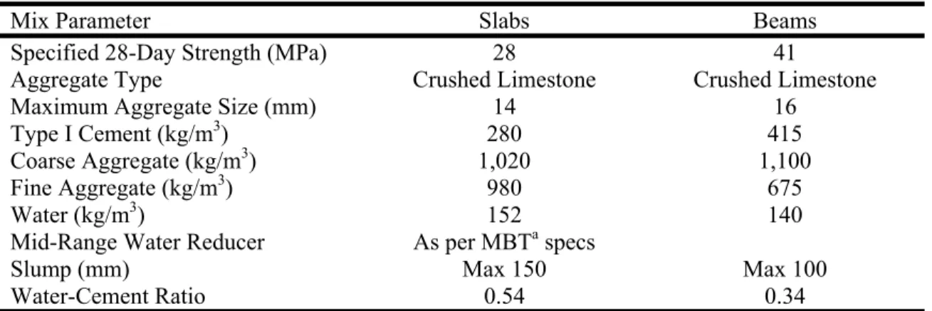
Mix Parameter Slabs Beams
Specified 28-Day Strength (MPa) 28 41
Aggregate Type Crushed Limestone Crushed Limestone
Maximum Aggregate Size (mm) 14 16
Type I Cement (kg/m3) 280 415
Coarse Aggregate (kg/m3) 1,020 1,100
Fine Aggregate (kg/m3) 980 675
Water (kg/m3) 152 140
Mid-Range Water Reducer As per MBTa specs
Slump (mm) Max 150 Max 100
Water-Cement Ratio 0.54 0.34
a
MBT = Master Builders Technologies Inc.
Table 3. Instrumentation for the slab testsa
Name Locationb Type Concrete Cover (mm)
TC16 Top of steel rebar [Section A] Temp. (°C) 50
TC17 Middle of steel rebars [Section A] Temp. (°C) 40
TC18 Bottom of steel rebars [Section A] Temp. (°C) 25
TC19 Inside Concrete Temp. (°C) 125
TC20 Inside Concrete Temp. (°C) 100
TC21 Inside Concrete Temp. (°C) 75
TC22 Inside Concrete Temp. (°C) 50
TC23 Inside Concrete Temp. (°C) 30
TC24 Inside Concrete Temp. (°C) 15
TC43 FRP/Concrete Interface Temp. (°C) -0.76
TC44 VG/FRP Interface Temp. (°C) -1
TC45c EI/VG Interface Temp. (°C) -20 or -39
FT1-FT4 Furnace Interior Temp. (°C) -
UN1-UN5 Unexposed Surface Temp. (°C) -
a
Refer to Figure 3
b
All sensors were located at Section B unless otherwise noted
c
Table 4. Instrumentation for the beam testsa
Name Locationb Type Concrete Cover
(mm)
TC10 FRP/Concrete interface [Section C] Temp. (°C) -0.76
TC11 VG/FRP interface [Section C] Temp. (°C) -1
TC12 EI-R/VG interface [Section C] Temp. (°C) -26 or –39
TC13/15 FRP/Concrete interface (side) Temp. (°C) -1
TC16 FRP/Concrete interface [Section A] Temp. (°C) -0.76
TC17 VG/FRP interface [Section A] Temp. (°C) -1
TC18 EI-R/VG interface [Section A] Temp. (°C) -26 or –39
TC21 Top of 15M bar (left) Temp. (°C) 70
TC22 Bottom of 15M bar (middle) Temp. (°C) 55
TC23 Top of 15M bar (right) Temp. (°C) 70
TC24 Inside Concrete (centerline) Temp. (°C) 85
TC25 Inside Concrete (centerline) Temp. (°C) 120
TC26 Inside Concrete (centerline) Temp. (°C) 155
TC27 Inside Concrete (left) Temp. (°C) 222
TC28 Inside Concrete (right) Temp. (°C) 222
TC29 Inside Concrete on bottom lateral bar (left) Temp. (°C) 302
TC30 Inside Concrete on bottom lateral bar (right) Temp. (°C) 302
TC31 Inside Concrete at lower transverse flange bar Temp. (°C) 302
TC32 Inside Concrete at lower transverse flange bar Temp. (°C) 302
TC33 Inside Concrete at lower transverse flange bar Temp. (°C) 302
TC34 Inside Concrete at upper transverse flange bar Temp. (°C) 51 (from top)
TC35 Inside Concrete at upper transverse flange bar Temp. (°C) 51 (from top)
TC36 Inside Concrete at upper transverse flange bar Temp. (°C) 51 (from top)
TC37 Inside Concrete at upper transverse flange bar Temp. (°C) 51 (from top)
TC38 Inside Concrete at upper transverse flange bar Temp. (°C) 51 (from top)
TC40 Bottom of 15M bar (left) [Section A] Temp. (°C) 55
TC41 Bottom of 15M bar (right) [Section A] Temp. (°C) 55
TC43 FRP/Concrete interface Temp. (°C) -0.76
TC44 VG/FRP interface Temp. (°C) -1
TC45 EI-R/VG interface Temp. (°C) -26 or –39
UN1 Unexposed face, center of web [Section D] Temp. (°C) -
UN2 Unexposed face, center of web [Section E] Temp. (°C) -
UN3 Unexposed face, center of flange, left [Section B] Temp. (°C) -
UN4 Unexposed face, center of web [Section B] Temp. (°C) -
UN5 Unexposed face, center of flange, right [Section B] Temp. (°C) -
UN6 Unexposed face, center of flange, left [Section F] Temp. (°C) -
UN7 Unexposed face, center of web [Section F] Temp. (°C) -
UN8 Unexposed face, center of flange, right [Section F] Temp. (°C) -
UN9 Unexposed face, center of web [Section G] Temp. (°C) -
SG21 On long. tension rebar, left Axial strain (µε) 70
SG22 On long. tension rebar, right Axial strain (µε) 70
SG23 On long. compression rebar, left Axial strain (µε) 51 (from top)
SG24 On long. compression rebar, right Axial strain (µε) 51 (from top)
SG25 On long. tension rebar, right Axial strain (µε) 70
SG26 On long. compression rebar, right Axial strain (µε) 51 (from top)
DF1 Centre of web [Section A] Deflection (mm) -
DF2 Centre of web [Section C] Deflection (mm) -
DF3 Centre of web Deflection (mm) -
DF4 Centre of flange Deflection (mm) -
FU1-FU9 Furnace temperature Temp. (°C) -
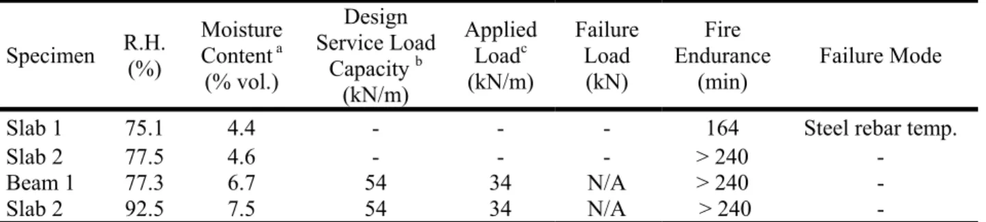
a
Table 5. Summary of results of fire endurance tests on slabs and beams Specimen R.H. (%) Moisture Content a (% vol.) Design Service Load Capacity b (kN/m) Applied Loadc (kN/m) Failure Load (kN) Fire Endurance (min) Failure Mode
Slab 1 75.1 4.4 - - - 164 Steel rebar temp.
Slab 2 77.5 4.6 - - - > 240 -
Beam 1 77.3 6.7 54 34 N/A > 240 -
Slab 2 92.5 7.5 54 34 N/A > 240 -
a
Determined in accordance with ULC S101 [9].
b Determined in accordance with CSA S806 [5]. Refer to Appendix A. c
20 8 20 8 1331 172 172 954
15M steel rebar 10M steel rebar
Figure 1. Reinforcement details of slabs 1 and 2
30 5 30 5 305 305 305 25 15 2 PLAN: SECTION A-A: NTS A A NTS Concrete: 28MPa Aggregate: Carbonate 25mm concrete cover Reinforcement: 15M (longitudinal) 10M (transverse) No. of specimens: 8 *All dimensions in mm
Figure 2. Reinforcement details for beams 1 and 2
26-10M stirrups at 150 o/c 209 wide by 309 high (measured at CL)
40
0
Clear concrete cover 40 mm to stirrups
ELEVATION: CROSS SECTION:
CROSS SECTION: Detail
All bars 10M unless otherwise specified Spaced at 150 mm o/c along beam 20M bars 40 40 100 150 150 20 40 40 40 1220 1220 300 150 250 3806 47 47 3900
Figure 3. Slab instrumentation details
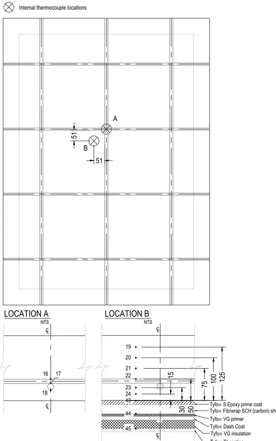
Internal thermocouple locations
51 51 A B
LOCATION A
18 17 16 CL Tyfo® EI coating Tyfo® VG insulation Tyfo® Dash Coat Tyfo® VG primerTyfo® Fibrwrap SCH (carbon) sheets Tyfo® S Epoxy prime coat
12 5 10 0 75 50 30 22 15 45 24 23 44 43 19 20 21
LOCATION B
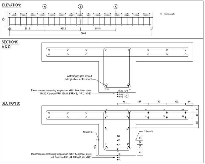
L C CL L C NTS NTSFigure 4a. Internal thermocouples for beams 400 ELEVATION: A B SECTIONS A & C: SECTION B:
All thermocouples bonded to longitudinal reinforcement
C
Thermocouples measuring temperature within the exterior layers 16&10: Concrete/FRP, 17&11: FRP/VG, 18&12: VG/EI
Thermocouples measuring temperature within the exterior layers 43: Concrete/FRP, 44: FRP/VG, 45: VG/EI 3806 951.5 951.5 951.5 51 47 80 150 150 157 94 60 51 35 35 35 21 23 22 24 25 26 27 28 29 30 31 32 33 34 35 36 37 38 40 (A) 41 (A) 43 44 16 (A), 10 (C) 17 (A), 11 (C) 18 (A), 12 (C) 45 Thermocouple 13 (Beam 1) 125 15 (Beam 2)
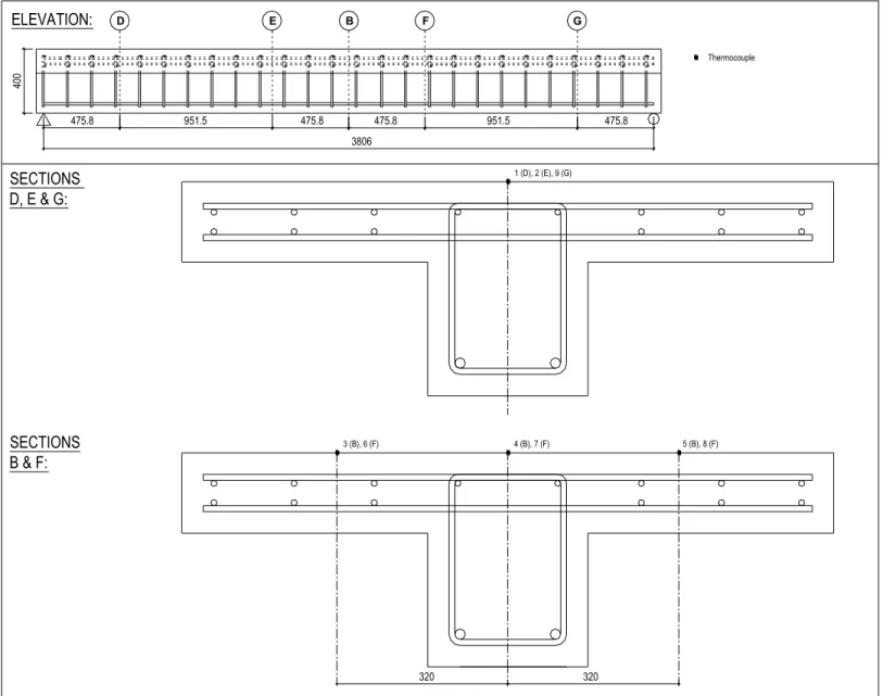
Figure 4b. Unexposed thermocouples for beams 400 ELEVATION: D B SECTIONS D, E & G: SECTIONS B & F: G 3806 1 (D), 2 (E), 9 (G) Thermocouple 475.8 E 951.5 475.8 F 475.8 951.5 475.8 320 320 4 (B), 7 (F) 3 (B), 6 (F) 5 (B), 8 (F)
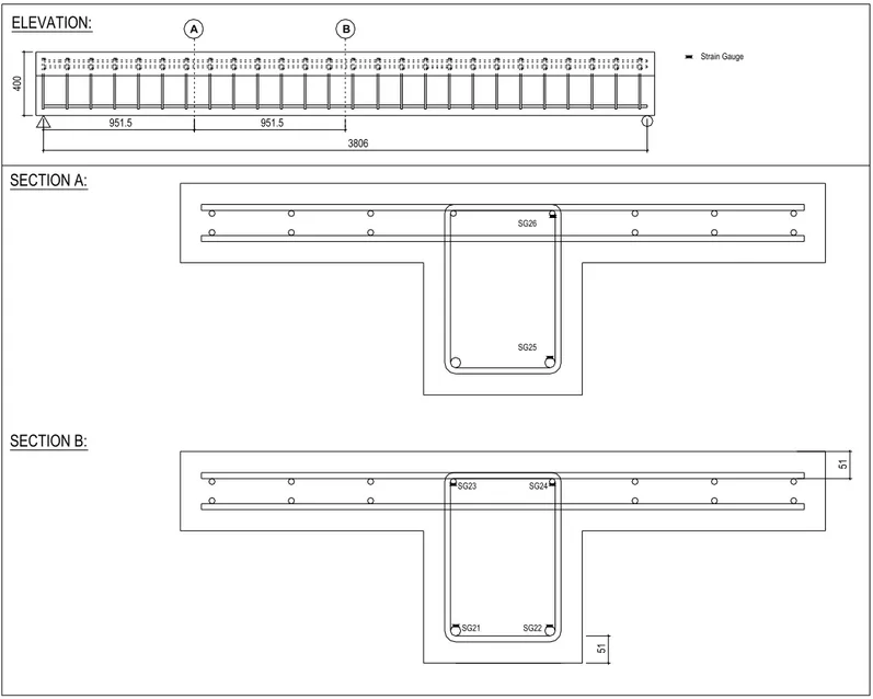
Figure 4c. Strain gauges for beams 400 ELEVATION: A B SECTION A: SECTION B: 3806 951.5 951.5 51 51 SG23 SG24 SG21 SG22 SG25 SG26 Strain Gauge
400 ELEVATION: A B SECTIONS A & C: SECTION B: C 3806 951.5 951.5 951.5 1 (A), 3 (C) Displacement Gauge 2 320 4
Figure 5. Strengthening and insulation details for slabs
Concrete
Tyfo® S Prime coat
2 layers Tyfo® Fibrwrap SCH (carbon) composite
Tyfo® VG Primer Tyfo® Dash Coat Tyfo® VG (see table) Tyfo® EI (see table)
Slab 1 Slab 2
Tyfo® VG
Tyfo® EI
Applied in multiple lifts to the maximum thickness possible (approx. 19mm)
Applied in multiple lifts to the maximum thickness possible (approx. 38mm)
Figure 6. Strengthening and insulation details for beams
UL Fire Test
Beam-Slab Assembly: FRP Strengthening & Insulation Scheme
Gap Gap
Total Length available= 3900mm (153.5 in.) 150mm 150mm Chamfer: 25mm (1 in.) Chamfer: 25mm (1 in.) 150mm (6 in.) 250mm (10 in.) 300mm (12 in.) 1220mm (48 in.) 1220mm (48 in.) 250mm (10 in.) 300mm (12 in.) 150mm (6 in.)
2 layers Tyfo® SEH
System U-Wrap 1 layer Tyfo® SCH System Flexural Strip Tyfo VG® Insulation 25/ 38mm (1/ 1.5 in.) thick Tyfo VG® Insulation 25/ 38mm (1/ 1.5 in.) thick Tyfo® SCH System
Tyfo® SCH System U-Wrap
Section A Section B 125mm (5 in. ) extension 125mm (5 in. ) extension C SupportL C SupportL Beam Elevation N.T.S. N.T.S. N.T.S. Tyfo® SCH System
Material Test 1 Test 2
Tyfo® SCH Flex No. of Layers 1 1 Tyfo® SCH U-Wrap No. of Layers 2 2
Tyfo® VG Insulation (Thickness) 25mm (1") 38mm (1.5") Tyfo® EI-R 0.13mm (5 mils) 0.13mm (5 mils) 100mm (4 in.)
100mm (4 in.)
650mm (25.5") 650mm (25.5")
0 60 120 180 240 300 Temperature (ºC ) 0 200 400 600 800 1000 Slab 1: EI/VG Slab 2: EI/VG Slab 1: across FRP Slab 2: across FRP Time (minutes) (a) 0 60 120 180 240 300 Temperature ( ºC ) 0 200 400 600 800 1000
Slab 1: Steel reinforcement Slab 2: Steel reinforcement Slab 1: unexposed surface Slab 2: unexposed surface
Time (minutes)
(b)
Figure 7. Comparison of temperatures at various locations within Slabs 1 and 2 during fire endurance
tests
(a) Temperatures at the EI/VG interface and across the flexural FRP sheet (b) Temperatures at the base of the rebar and at the unexposed surface
Time [minutes] 0 50 100 150 200 250 300 Temperat ure [º C ] 0 200 400 600 800 1000 Beam 1: EI/VG Beam 2: EI/VG Beam 1: across FRP Beam 2: across FRP (a) Time [minutes] 0 50 100 150 200 250 300 Tem p erature [ºC] 0 50 100 150 200 250
Beam 1: beam steel rebar Beam 2: beam steel rebar Beam 1: unexposed surface Beam 2: unexposed surface
(b)
Figure 8. Comparison of temperatures at various locations within Beams 1 and 2 during fire endurance
tests
(b) Temperatures at the EI/VG interface and across the FRP sheet (c) Temperatures at the base of the rebar and at the unexposed surface
APPENDIX A
Load calculations for beams
A.1 Introduction
This appendix details the design calculations for the beam-slab assemblies tested in this thesis. It also includes calculations related to the strengthening limits for a structural member strengthened with FRP, as well as calculation of the theoretical load-deflection relationship for the beam-slab assemblies.
The beams were first designed in an unstrengthened state using the Canadian concrete design code [10] and the American building code [11]. A live occupancy load of 2.4kPa over a tributary width of 3m was assumed for the initial part of the design. The strengthening scheme was then designed for the beams assuming an increase live occupancy load of 4.8kPa. Both the Canadian FRP design guidelines [5, 7] and American ACI 440.2R-02 design guide [6] were consulted.
A.2 Design Assumptions a.) Length of beam
The beam furnace has a total clearance of 3962mm [156 in.] across its width; therefore the beam could theoretically be this long. However, in order to allow for expansion of the beam due to thermal effects (which are estimated to cause a total increase in beam length of 40mm), a gap should be allowed between the wall of the furnace and the beam, as shown in the following figure.
Figure A.1: Profile of Beam Resting on Concrete Sills in Furnace
150 Gap Chamfer: 25 Gap Chamfer: 25 150 Total length available =
3962mm
CL support CL support
Note: All dimensions in mm
Assuming a gap of 25mm at each end gives a total maximum length of 3912mm, which was rounded down to 3900mm for simplicity (and results in an actual gap of 31mm). The test span of the beam may then be determined based on this total length, and knowing that there is a 25mm chamfer on each sill.
mm span Test mm width this of centre at is Support of CL mm chamfer gap width Support 3806 47 47 3900 47 94 ) ( 25 ) ( 31 150 = − − = ∴ = = − − =
Just prior to testing, it was decided to test the beam as a restrained assembly. Thus, the
aforementioned gaps were filled with steel shims, and the beams were restrained axially
.
b.) Load on beam
The steel reinforcement in the concrete section was designed to resist a 2.4kPa live load capacity. An FRP repair scheme was then designed assuming an increased live load of 4.8kPa. The beams also must resist the effects of a 1kPa dead weight from partitions and self-weight. The tributary width used to determine total loads was 3m (implies 3m theoretical beam spacing, which is reasonable).
c.) Beam dimensions
The beam dimensions used in design are shown in the figure below. Clear cover to the stirrups was assumed to be 40mm, as required by both CSA A23.3-94 [10] and ACI 318M-99 [11].
Figure A.2: Beam Dimensions
300mm [12 in.] 1220mm [48 in.]
150mm [6 in.]
250mm [10 in.]
d.) Material properties
The following material types and properties have been assumed for design. Table A.1: Material Properties
Material Strength Concrete
[Carbonate Aggregate]
from material tests
Compressive: 44 MPa Tensile: Negligible
Ultimate strain: 0.0035 (Can) 0.003 (US) Steel: 20M
from mill report
Yield: 500 MPa Modulus: 250 GPa Ultimate strain: 0.002 Steel: 10M
from mill report
Yield: 400 MPa Modulus: 250 GPa Ultimate strain: 0.002 Carbon FRP [SCH41, Fyfe] from manufacturer Ultimate: 745 MPa Modulus: 61.5 GPa Ultimate strain: 0.012
e.) Design codes
Both Canadian and American design codes were consulted in the design of the beams. For design of the unstrengthened reinforced concrete beams, the codes used were:
- CSA A23.3-94 [10] Design of Concrete Structures
- ACI 318M-99 [11] Building Code Requirements for Structural Concrete
For design of the FRP-strengthened beams, the codes used were:
- ISIS Canada Design Manual No. 4 [7] Strengthening Reinforced Concrete Structures
with Externally-Bonded Fibre Reinforced Polymers
- ACI Committee 440, Draft Document [6], Guide for the Design and Construction of
Externally Bonded FRP Systems for Strengthening Concrete Structures
- ACI 216R-81 Guide for Determining the Fire Endurance of Concrete Elements
A.3 Factored Loads
Factored load (Live load of 2.4kPa)
Unfactored Dead Load
The dead load is made up of the self-weight of the beams and an assumed load due to walls and partitions. The resulting unfactored dead load is then:
partitions weight self DL DL DL= − +
m
kN
DL
self−weight=
23
.
5
⋅
(
3
.
0
×
0
.
15
+
0
.
25
×
0
.
3
)
=
12
.
3
/
m kN width tributary m kPa DLpartitions =(1.0 )⋅(3.0 )=3.0 /m
kN
DL
=
12
.
4
+
3
.
0
=
15
.
3
/
Unfactored Live Load
width
tributary
LL
UDL
LL
(
)
=
⋅
(
)
Live load is the standard 2.4kPa occupancy load distributed over an assumed 3m tributary width. Thus, the unfactored live load is:
m
kN
m
kPa
)
(
3
)
7
.
2
/
4
.
2
(
⋅
=
=
Factored Load [10]According to CSA A23.3-94 [10], the dead load factor, αD, is 1.25 and the live load factor, αL, is
1.5. Multiplying these by the loads provides the factored live and dead loads
.
m
kN
DL
)
(
15
.
3
)
(
15
.
4
)
1
.
25
19
.
2
/
(
f=
⋅
α
D=
⋅
=
m
kN
LL
)
f(
7
.
2
)
L(
7
.
2
)
1
.
5
10
.
8
/
(
=
⋅
α
=
⋅
=
The factored uniformly distributed load is then:
m
kN
w
f=
19
.
3
+
10
.
8
=
30
/
Finally, the factored flexural and shear loads that on a simply supported beam are determined as:
m
kN
L
w
M
f=
f⋅
=
⋅
=
54
.
3
−
8
806
.
3
30
8
2 2kN
L
w
V
f f57
2
806
.
3
30
2
=
⋅
=
⋅
=
Factored Load [11]According to ACI 318M-99 [11], the dead load factor, αD, is 1.5 while the live load factor, αL, is
1.7, resulting in the following factored loads:
m
kN
LL
)
f(
7
.
2
)
L(
7
.
2
)
1
.
7
12
.
2
/
(
=
⋅
α
=
⋅
=
m
kN
DL
)
f(
15
.
3
)
D(
15
.
4
)
1
.
4
21
.
6
/
(
=
⋅
α
=
⋅
=
The factored uniformly distributed load is then:
m
kN
w
f=
21
.
6
+
12
.
2
=
33
.
8
/
Finally, the factored flexural and shear loads that on a simply supported beam are determined as:
m
kN
L
w
M
f=
⋅
=
⋅
=
61
−
8
85
.
3
8
.
33
8
2 2kN
L
w
V
f64
.
2
2
85
.
3
8
.
33
2
=
⋅
=
⋅
=
Therefore, in summary, the factored loads at the 2.4kPa level are:
Canadian American
54 kN-m Mf 61 kN-m
57 kN Vf 64 kN
Factored Load (Live load of 4.8kPa)
Unfactored Dead Load
The dead load remains the same as calculated previously.
Unfactored Live Load
As stated previously, the live load intensity used for strengthening calculations was increased to 4.8kPa, producing an unfactored distributed live load of:
m
kN
width
tributary
m
kPa
LL
=
(
4
.
8
)
⋅
(
3
)
=
14
.
4
/
Factored Load [10]Using the same load factors as before, the factored live load and uniformly distributed load become: