R
ESEARCHA
RTICLEAn active control concept for the TALC space telescope
Christophe Collettea,*, Simon Chesneb, Sébastien Correiab, and Gilles Durandc
a
Université Libre de Bruxelles, BEAMS department, 50 av. F.D. Roosevelt, 1050 Brussels, Belgium b
Université de Lyon, CNRS INSA-Lyon, LaMCoS UMR5259, 69621 Villeurbanne, France c
CEA Saclay, DSM-IRFU-SAP, 91191 Gif-sur-Yvette cedex, France
Received: 8 December 2015 / Received infinal form: 18 November 2016 / Accepted: 13 December 2016 Abstract. The paper presents a simplified dynamical model of the TALC telescope. Even though the model is simple, it represents partially the system dynamics, which allowed elaborating preliminary control strategies to damp system resonances. Using active cables, it has been shown that the resonances can be significantly damped, and that the control authority increases as a function of the number of active cables. Additionally, it has been shown that, even with a low value of the control gain, the RMS value of a quantity representative of the optical path difference can be reduced by a factor three.
Keywords: Space telescope / active cable / structural damping
1 Introduction
Further space exploration in the far-infrared requires larger telescopes, in order to improve the spatial resolution of captured images. To this purpose, the Thinned Aperture Light Collector (TALC) concept has been recently proposed [1,2], which offers novel perspectives for deep space explorations. A conceptual design of TALC is shown
inFigure 1(left). The general structure is one of a bicycle
wheel, where the inner side of the segments in compression to each other plays the role of the rim. The segments are linked to each other using a pantograph scissor system that let the segments extend from a pile of mirrors to a parabolic ring keeping high stiffness at any time during the deployment. The inner corners of the segments are linked to a central axis using spokes as in a bicycle wheel. The primary mirror has an external diameter of 20 m. Thanks to an original folding concept, it can be stored in the fairing of Ariane 6 during theflight, then deployed in space.
In this paper, we present a simplified model of the telescope, using lumped masses connected by springs. Even though the model discussed is extremely simple, it already contains interesting features of the telescope dynamics, allowing elaborating control strategies for damping structural vibrations, and for controlling the shape of the primary mirror at its veryfirst resonance frequencies.
The paper is structured as follows.Section 2describes the simplified model, Section 3 presents the control approach, Section 4 shows an example of the control performance, expressed in terms of the optical path difference, andSection 5draws the conclusions.
2 Simplified model of TALC
The simplified lumped-mass model of TALC is shown in
Figure 1(right). The mass of the vertical beam,mb= 100 kg,
has been equally distributed on the three massesm1,m2and
m3. It represents a 16 meters length tube of carbon, with a
diameter of 0.35 m and a thickness of 4 mm. The mass of the primary mirror is equally distributed on two massesm4and
m5. Each mass moves only in the horizontal direction.
Additionally,m2includes the mass of a telescopic arm
(ms= 30 kg), which connects the telescope to the satellite
at the middle of the central boom. The upper mass m3
includes the mass of the optics, taken asmo= 750 kg. The
numerical values of the masses have been chosen as follows:m1=mb/3;m2=mb/3 +ms;m3=mb/3 +mo;m4=
m5= 900 kg (the mirror ring is a combination of 18 mirrors
of 100 kg). The stiffness of the springs connectingm1,m2
andm3have been chosen to get afirst flexible mode of the
beam around 8.2 Hz, where m2 moves in opposite phase
with the other ones, tofit with the first bending mode of this part of the structure. The stiffness of the cables is kc= 2.8 MN/m, and the stiffness of the piezoelectric
actuators is taken as ka= 20 MN/m. These values are
typical values found in the literature [3]. The stiffness betweenm4andm5is tuned askm= 150 kN/m, in order to
obtain a first flexible mode of the mirror around 3 Hz
* e-mail:[email protected] Mechanics & Industry 18, 510 (2017) © AFM,EDP Sciences2017
DOI:10.1051/meca/2016088
M
echanics
&
I
ndustry
Available online at: www.mechanics-industry.org(ovalisation), as found from a previousfinite element study [4]. Finally, a modal damping of 0.1% has been assigned to all the modes. This value is typical for space structures.
Figure 2shows an example of transmissibility between
the mass m3, representing the top of the central boom
where the optics is located, and the middle massm2, where
the telescope is attached to the satellite. Thisfigure shows that the transmissibility is dominated by two peaks. The first one, at 0.76 Hz, corresponds to a motion of m2out of
phase with the rest of the structure; the second one, at 15.1 Hz, corresponds to a motion ofm3out of phase with the
rest of the structure.
In the following section we will study the possibility to damp these peaks with an active control of the telescope vibrations in order to reduce the sensitivity of the optical path difference (represented byx3–x4) to external
distur-bances.
3 Active damping with piezoelectric tendons
The strategy considered in this section takes advantage of the cables to act directly on the telescope dynamics. Basically, we propose to equip some of the cables with
active tendons, constituted of a piezoelectric actuator in series with a force sensor, as shown inFigure 3. Through this embodiment, we can use decentralized loops in each active tendon, which have the interesting property to be unconditionally stable. Such a strategy has already been successfully applied to other large structures, e.g. for particle collider [3] or gravitational wave detector [5]. The details of the control strategy can be found in these references, and an improvement of the strategy can be found here [6]. The controller consists of an integrator and a high-pass filter. As the force is proportional to the acceleration, the signal after integration is proportional to the absolute velocity, which can be used to add some viscous damping. The high-passfilter avoids low-frequency drifts in the control signal. One can notice that it is also foreseen to use the actuators for controlling the shape of the mirror, i.e. the distance and orientation of each segment. However, this latter functionality is not studied in this paper, which focuses only on active damping.
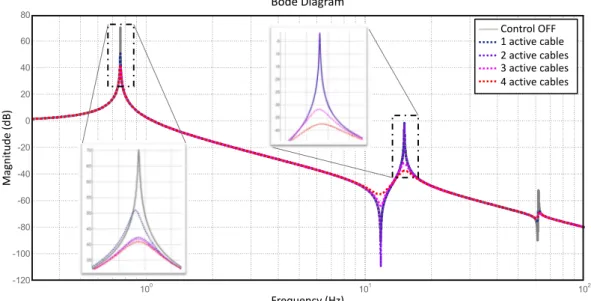
Figure 4shows an example of results obtained on the
transmissibility x3/x2. The active cables have a clear
authority on both peaks, which is increasing as a function of the number of active cable. For clarity, an equivalent
m1 m3 Central beam Mirror ring m2 m4 m5 Secondary mirror OpƟcal path Primary mirror km
Fig. 1. Conceptual design of the TALC (left) and simplified lumped mass model (right).
Piezoelectric actuator Force sensor Passive cable kc ka Controller Fig. 3. Scheme of an active cable.
100 101 102 -120 -100 -80 -60 -40 -20 0 20 40 60 80 Control OFF 1 active cable 2 active cables 3 active cables 4 active cables Bode Diagram Frequency (Hz) Magnitude (dB)
Fig. 2. Transmissibility (x3/x2) between the massm3, where is optics is located, and the middle massm2, where the telescope is attached to the satellite.
modal damping factor for both peaks is shown inFigure 4
as a function of the number of active cable and their positions (Superior (S) for the cables attached tom3and
inferior (I) to the cables attached tom1). As one could have
anticipated, the damping factor of both modes increases with the number of active cables, while taking always the same controller for all the cables. The control gain has been taken intentionally very low as we aim to illustrate a control strategy, rather than finding the optimal values. One can observe that the two inferior cables have no authority on the second resonance. This is obviously due to the shape of the mode which does not strain these cables. The superior cables appear as more efficient to damp these vibrations. As the optic system is attached on the top of the central beam (onm3) more important stress go through the
superior cables. This result is linked to the mass distribution of the structure and the resulting mode shape.
4 Impact on optical path difference
As the main goal of the active stabilization of the telescope is to ensure high quality images, we have tested the impact of the proposed controller on x3–x4, assumed as a quantity
representative of the Optical Path Difference (OPD).
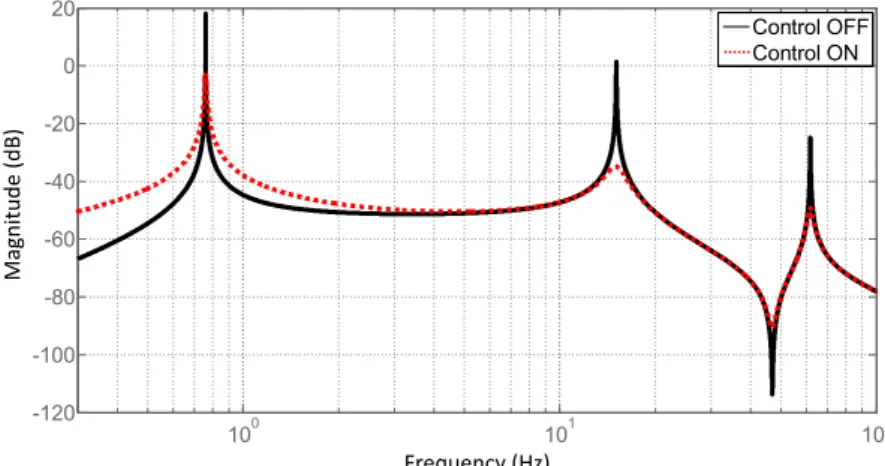
Figure 5 shows the transmissibility betweenx3–x4andx2,
which is the motion of the anchorage point of the telescope on
the satellite. The curve shows again two peaks, correspond-ing to the two peaks which are visible inFigure 2. The solid curve has been obtained when the controller is turned OFF, and the dashed red curve has been obtained with four active cables, and the same controller as inSection 2.
One sees that the reduction of the overshoots has been obtained at the cost of a slight degradation at low frequency, indicative of a softening of the feedback operation. In order to further estimate the effect of the controller on the OPD, we have calculated the response of the system to an input motion atx2, whose power spectral
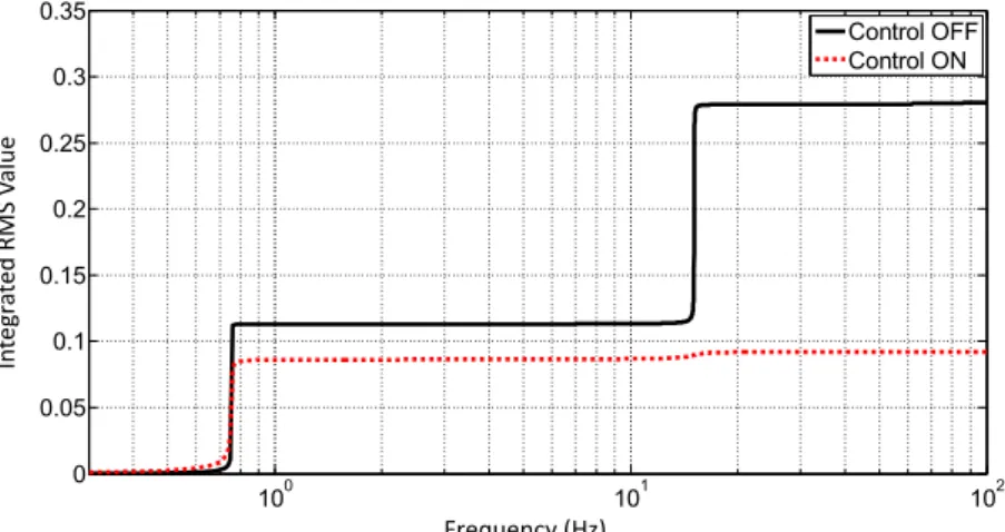
density has been chosen arbitrarily as 1 mm2/Hz.Figure 6
shows the integrated RMS value of x3–x4 when the
controller turned OFF (black curve) and turned ON (dashed red curve).
Without control, one sees that the contributions to the RMS are mainly due to the two peaks, creating two steps in the cumulated RMS. With control, the total RMS is reduced by a factor three, due to the increase of structural damping.
5 Conclusion
In this paper, we have presented a simplified analytical model of the TALC telescope which contains only five d.o.f. Even though the model is over-simplified on many
ξ(%)
Peak 1 (0,76Hz) Peak 2 (15,1Hz)
Active cables (position and number) S
I II IS SS IIS ISS IISS
Fig. 4. Damping factor of the two poles dominating the transmissibility (Fig. 2) as a function of the number of active cables and their position (I for inferior and S for Superior).
100 101 102 -120 -100 -80 -60 -40 -20 0 20 Control OFF Control ON Frequency (Hz) Magnitude (dB)
Fig. 5. Transmissibility between (x3–x4), representing the optical path difference (OPD) and the motion of the centre of the boom (x2), when the control of the cables is turned OFF and turned ON with four active cables.
aspects, it already contains some interesting features of the system dynamics, which allowed elaborating prelimi-nary control strategies. In particular, we have studied the possibility to damp system resonances using active cables. It has been shown that the control strategy allow to control the peaks, and that the authority increases as a function of the number of active cables. This study also shows that the position of the cable is a critical parameter. In future more complex models, stress distribution should be carefully analyzed before positioning the active cables. Additionally, it has been shown that, even with a low value of the control gain, the RMS value of a quantity assumed as representative of the OPD can be reduced by a factor three.
In the near future, it is planned to test the proposed strategy on a more realistic model of the telescope dynamics.
References
[1] G. Durand, M. Sauvage, A. Bonnet, L. Rodriguez, S. Ronayette, P. Chanial, L. Scola, V. Révéret, H. Aussel, M. Carty, M. Durand, L. Durand, P. Tremblin, E. Pantin, M. Berthe, J. Martignac, F. Motte, M. Talvard, V. Minier, P. Bultel, TALC: a new deployable concept for a 20 m
far-infrared space telescope, in: Proc. SPIE 9143, Space Tele-scopes and Instrumentation 2014: Optical, Infrared, and Millimeter Wave, 9143-41, 2014
[2] M. Sauvage, G. Durand, L. Rodriguez, P. Chanial, J.-L. Starck, S. Ronayette, H. Aussel, V. Minier, F. Motte, E. Pantin, The Science case and data processing strategy for thinned aperture light collector: a project for 20 m far infrared space telescope, in: Proc. SPIE 9143, Space Telescopes and Instrumentation 2014: Optical, Infrared, and Millimeter Wave, 9143-42, 2014
[3] A. Bonnet, Le télescope TALC : Contrôle en position des miroirs Amortissement des vibrations, rapport interne INSA, 2013
[4] C. Collette, D. Tshilumba, L. Fueyo-Rosa, I. Romanescu, Conceptual design and scaled experimental validation of an actively damped carbon tie rods support system for the stabilization of future particle collider superstructures, Rev. Sci. Instrum. 84 (2013) 023302
[5] D. Tshilumba, L. Nuttal, T. Mac Donald, R. Mittelmann, B. Lantz, F. Matichard, C. Collette, Vibration analysis and control of the LIGO observatories large chambers and support piers, in: Proceedings of the ISMA Conference, Leuven, Belgium, 2014
[6] S. Chesne, A. Milhomem, C. Collette, Enhanced active damping offlexible structures with inherently stable power ports, in: 22nd International congress on sound and vibration, Florence, Italy, 2015
Cite this article as: C. Collette, S. Chesne, S. Correia, G. Durand, An active control concept for the TALC space telescope, Mechanics & Industry 18, 510 (2017)
100 101 102 0 0.05 0.1 0.15 0.2 0.25 0.3 0.35 Control OFF Control ON Frequency (Hz) In tegr at ed RMS V alue
Fig. 6. Integrated RMS value of the optical path difference (x3–x4) when the controller is turned OFF and turned ON with four active cables. A displacement of 1 mm2/Hz of the central massm2has been taken as input excitation.