HAL Id: hal-01338399
https://hal-univ-rennes1.archives-ouvertes.fr/hal-01338399
Submitted on 28 Jun 2016
HAL is a multi-disciplinary open access
archive for the deposit and dissemination of
sci-entific research documents, whether they are
pub-lished or not. The documents may come from
teaching and research institutions in France or
abroad, or from public or private research centers.
L’archive ouverte pluridisciplinaire HAL, est
destinée au dépôt et à la diffusion de documents
scientifiques de niveau recherche, publiés ou non,
émanant des établissements d’enseignement et de
recherche français ou étrangers, des laboratoires
publics ou privés.
Small end-fire superdirective folded meandered
monopole antenna array
Mohamad Hammoud, Abdullah Haskou, Ala Sharaiha, Sylvain Collardey
To cite this version:
Mohamad Hammoud, Abdullah Haskou, Ala Sharaiha, Sylvain Collardey. Small end-fire
superdirec-tive folded meandered monopole antenna array. Microwave and Optical Technology Letters, Wiley,
2016, 58 (9), pp.2122-2124. �10.1002/mop.29995�. �hal-01338399�
1
Small End-Fire Superdirective Folded Meandered
Monopole Antenna Array
Mohamad Hammoud, Abdullah Haskou, Ala Sharaiha, and Sylvain Collardey
IETR UMR CNRS 6164- Université de Rennes 1, Rennes, France;
Corresponding author: [email protected]
Abstract—In this letter, we present a compact four-element
superdirective antenna array operating at 900M Hz frequency band. In this antenna, only one element is excited while the others are parasitic-loaded elements. The antenna total dimensions are 231× 122mm2
and it has a total directivity of 11.6dBi and radiation efficiency of 46%. This antenna is significantly compact compared with others presenting the same directivity.
Keywords—Antenna array, superdirectivity, directivity, efficiency
I. INTRODUCTION
Some emerging wireless technologies require precise beam pointing in useful directions. Directional small-size antennas allow the development of new opportunities for their ap-plications in terms of spectral efficiency, radio interference-free deployment, reduced environmental impact, and reduc-ing exposure to electromagnetic fields. Since the pioneerreduc-ing works of I. Uzkov [1] and E.N. Gilbert and S.P. Morgan [2], significant research has been done on superdirective arrays [3-8]. Early works were conducted primarily on the design of wire antenna arrays [3-4]. Recently, several miniaturized planar parasitic superdirective antennas were presented [5-7]. One of the main issues of this kind of arrays is the poor radiation efficiency when we increase the number of the elements [8]. In [9] we have shown that as we increase the number of the elements in a superdirective array, we should also increase the inter-element spacing to obtain a good efficiency with a high directivity. In this letter, and based on this idea, we design an efficient and impedance-matched compact four-element parasitic superdirective antenna array. The proposed antenna is significantly smaller than commercial antennas with the same directivity. The rest of the letter is organized as follows: The proposed antenna geometry is described in section II. The simulation and experimental results are presented in section III. Finally, conclusions are drawn in section IV.
II. ANTENNAGEOMETRY ANDEXCITATION
COEFFICIENTS
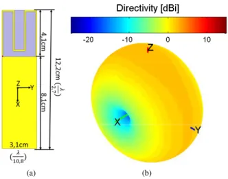
The unit element used in this array is a folded meandered monopole printed on a Rogers duroid/ RT5880 substrate (ϵr= 2.2, tan(δ) = 0.0009) with a thickness of 0.8mm (Fig.
1(a)). Its size is 122× 31mm2. It has a simulated (ANSYS HFSS [10]) resonance frequency around 900M Hz with a quasi-omnidirectional radiation pattern (a total directivity of 2.4dBi (Fig. 1(b))) and a radiation efficiency of around 100%.
(a) (b)
Fig. 1. The unit-element. (a) Geometry and dimensions and (b) simulated 3D total directivity radiation pattern.
The method proposed in [9] has been used to design a four-element array operating at 900M Hz frequency band with an inter-element spacing is 0.2λ due to the trade off between the antenna- dimensions, -directivity and -radiation efficiency [9]. The total size of the array is 231× 122mm2(1.4λ ×2.7λ ). First, the array current excitation coefficients were calculated to maximize the antenna directivity in the end-fire direction (ϕ = 90o, θ = 90o). The obtained excitation coefficients are
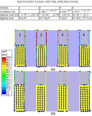
given in Table 1 (refer to Fig. 2 for elements order). Then, the array is transformed to a parasitic-loaded one where one element is excited while the others are loaded as explained in [9]. The values of the required optimal loads are given in Table 1. As it can be noticed some negative resistances are required, neglecting these resistances and loading the parasitic elements with the lumped elements given in Table 1, total directivities of 8.4, 11.6, 10.4 and 8.2dBi can be achieved in case of exciting the first, second, third or fourth element respectively. For example, when exciting the first element, the second, third and fourth are respectively loaded with 34.74pF , 7.6pF and 61.2Ω//77.5nH. The significant decrement in the parasitic array directivity when exciting the first or fourth element is due to neglecting important negative resistances and the high sensitivity of the antenna directivity to the excitation coefficients as the number of elements increases [9]. In analogy, the achieved directivity when exciting the second element is the highest due to the small values of the neglected
2
resistances and since the coupling with the other elements is the highest. Fig. 2 shows that the parasitic (when exciting the second element) array’s simulated surface current distribution is in a very good agreement with the fully-driven array’s one. In the next section, we shall detail the simulated and measured results for the parasitic array.
TABLE I. THE CALCULATED EXCITATION COEFFICIENTS,THE EQUIVALENT LOADS AND THE APPLIED LOADS.
Element 1 2 3 4
Excitation [A] 1 2.26ej−154.8o 2.24ej45o1.07ej−114.4o Optimal load [Ω]−4.79 + j40.37−19.02 − j5.09−j23.91 39.48 + j0.3 Applied load 12nH 34.74pF 7.6pF 61.2Ω//77.5nH 100.0 93.3 86.7 60.0 40.0 13.3 26.7 33.3 53.3 46.7 20.0 66.7 73.3 80.0 6.7 0.0 Jsurf [A/m]
Fig. 2. The surface current distribution in (a) fully-driven array and (b) parasitic array.
III. SIMULATION ANDEXPERIMENTALRESULTS
A prototype of this antenna was fabricated and measured to validate the results (Fig. 3(a)). Fig. 3(b) shows that the array measured input reflection coefficient is in a very good agree-ment with the simulated one. The simulated (S11 <−10dB) impedance bandwidth is around 7M Hz while the measured one is 6M Hz. The antenna far-field radiation pattern was measured using SATIMO Stargate SG 32 measuring system. Fig. 3(c) shows the array maximum total directivity as a function of the frequency. The figure shows that this directivity is highest at the the design frequency with a (Dmax− 1dB)
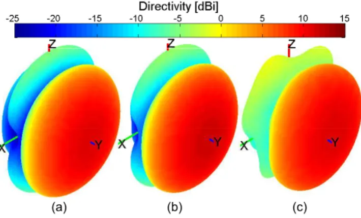
directivity bandwidth of 28.6M Hz in simulation and 34M Hz in measurement. It can be noted from Fig. 4 that the parasitic array 3D total directivity radiation pattern is in a very good agreement with the fully-driven array’s one. Concerning the parasitic array, the figure shows that the antenna is directive with a simulated directivity of 11.6dBi and a measured one
of 11dBi. This directivity is 1.2dBi higher than Harrington’s normal directivity limit for an antenna with the same size factor (ka = 2.46) [11]. The Half Power BeamWidth (HPBW) in horizontal (XoY) and vertical (YoZ) planes are respectively 48o and 58o in simulation and 45o and 56o in measurement. The simulated Front to Back Ratio (FBR) is 18.3dB while the measured one is 13dB (Fig. 5). Fig. 3(d) shows the antenna radiation efficiency. It can be noticed that this efficiency rapidly decreases when approaching the design frequency. This is mainly due to the superdirectivity phenomena; where the cur-rent opposition on the diffecur-rent elements cancels the antenna radiation in certain directions, and hence, reduces its radiation efficiency. The antenna has a simulated radiation efficiency of 46% (a gain of 8.3dBi) and an experimental one (measured in a reverberation chamber [12]) of 47.3% (a gain of 8dBi). The antenna 3D co-polar directivity radiation pattern given in Fig. 6 shows a very good agreement between the simulated and measured patterns. The maximum co-polar directivity is also in the end-fire (oY) direction with a simulated value of 11.6dBi and a measured one of 11dBi. The antenna cross-polar 3D directivity radiation pattern is given in Fig. 7. The maximum cross-polar directivity is in the broadside (oZ) direction and it has a simulated value of −4.7dBi and a measured one of −1.2dBi. The small difference between simulated and measured results can be attributed to the cable effect, the uncer-tainties in the SMD components values and measuring system and environment. This antenna is very compact compared to others presenting the same directivity. A Yagi-Uda antenna with the same directivity is around 535× 175 × 40mm3[13].
(a) 800 900 1000 1100 −30 −25 −20 −15 −10 −5 0 Frequency [MHz] S11 [dB] Simulated Measured (b) 8002 900 1000 1100 4 6 8 10 12 Frequency [MHz] Dmax [dBi] Simulated Measured (c) 800 850 900 950 1000 1050 1100 40 50 60 70 80 90 100 ηrad [%] Frequency [MHz] Simulated Measured (d)
Fig. 3. Parasitic array simulated and measured parameters. (a) A photograph of the realized prototype, (b) input reflection coefficient magnitude in dB, (c) maximum total directivity and (d) radiation efficiency.
3
(a) (b) (c)
Fig. 4. Proposed array 3D total directivity radiation pattern. (a) Simulated driven, (b) simulated parasitic and (c) measured parasitic.
−15 −5 5 15 30 210 60 240 90 270 120 300 150 330 180 0 φ [°] Directivity [dBi] Simulated driven Simulated parasitic Measured parasitic (a) −15 −5 5 15 30 210 60 240 90 270 120 300 150 330 180 0 θ [°] Directivity [dBi] Simulated driven Simulated parasitic Measured parasitic (b)
Fig. 5. Proposed array simulated and measured 2D total directivity radiation pattern. (a) Horizontal plane and (b) vertical plane.
(a) (b)
Fig. 6. Parasitic array 3D co-polar directivity radiation pattern. (a) Simulated and (b) measured.
IV. CONCLUSION
In this letter, we presented a compact four-element parasitic-loaded superdirective array for 900M Hz frequency band for UHF RFID readers. The antenna dimensions were 231× 122mm2and it presented a total directivity of 11.6dBi and a radiation efficiency of 46%. This array is significantly compact compared with antennas with the same directivity available in the market.
(a) (b)
Fig. 7. Parasitic array 3D cross-polar directivity radiation pattern. (a) Simulated and (b) measured.
ACKNOWLEDGMENT
This work was done with the funding of the French National Research Agency as part of the project SOCRATE and the support of the Images et Reseaux cluster of Brittany region, France.
REFERENCES
[1] I. Uzkov, "An Approach to the Problem of Optimum Directive Antennae
Design", Comptes rendues (Doklady) de l’académie des sciences de
l’URSS, Vol. 53, no. 1, 1946.
[2] E. N. Gilbert, and S. P. Morgan, "Optimum Design of Directive Antenna
Arrays Subject to Random Variations", Bell System Technical Journal,
Vol. 34, pp. 637-663, May 1955.
[3] E. E. Altshuler, T. H. O’Donnell, A.D. Yaghjian, and S. R. Best, "A
Monopole Superdirective Array", IEEE Transactions on Antennas and
Propagation, Vol. 53, no. 8, pp. 2653-2661, August 2005.
[4] T. H. O’Donnell, and A. D. Yaghjian, "Electrically Small Superdirective
Arrays Using Parasitic Elements", IEEE Antennas and Propagation
Society International Symposium 2006, pp. 3111,3114, 9-14 July 2006. [5] M. Pigeon, A. Sharaiha, and S. Collardey, "Miniature and Superdirective
Two Elements Endfire Antenna Array", 8th European Conference on
Antennas and Propagation (EuCAP 2014), 6-11 April 2014.
[6] A. Haskou, A. Sharaiha, and S. Collardey, "Integrating Superdirective
Electrically Small Antenna Arrays in PCBs", IEEE Antennas and
Wireless Propagation Letters, doi: 10.1109/LAWP.2015.2425913. [7] A. Clemente, M. Pigeon, L. Rudant, and C. Delaveaud, "Design of a
Super Directive Four-Element Compact Antenna Array Using Spherical Wave Expansion, IEEE Transactions on Antennas and Propagation,
Vol. 63, no. 11, pp. 4715-4722, November 2015.
[8] N. Yaru, "A Note on Super-Gain Antenna Arrays, in Proceedings of the IRE, Vol. 39, no. 9, pp. 1081-1085, September 1951.
[9] A. Haskou, A. Sharaiha, and S. Collardey, "Design of Small Parasitic
Loaded Superdirective End-Fire Antenna Arrays", IEEE Transactions on
Antennas and Propagation, Vol. 63, no. 12, pp. 5456-5464, December 2015.
[10] ANSYS HFSS, Pittsburg, PA 15219, USA.
[11] R. F. Harrington, "On the Gain and Beamwidth of Directional
Anten-nas", IRE Transactions on Antennas and Propagation, pp. 219-225, July
1958.
[12] G. Le Fur, C. Lemoine, P. Besnier, A. Sharaiha, "Performances of
UWB Wheeler Cap and Reverberation Chamber to Carry Out Efficiency Measurements of Narrowband Antennas", IEEE Antennas and Wireless
Propagation Letters, Vol. 8, pp. 332,335, 2009.
[13] [Online]. Available: http://avalanwireless.com/marketing_resources/ product_briefs/AW11-900.pdf