HAL Id: hal-01620031
https://hal.archives-ouvertes.fr/hal-01620031
Submitted on 15 Feb 2019
HAL is a multi-disciplinary open access
archive for the deposit and dissemination of
sci-entific research documents, whether they are
pub-lished or not. The documents may come from
teaching and research institutions in France or
abroad, or from public or private research centers.
L’archive ouverte pluridisciplinaire HAL, est
destinée au dépôt et à la diffusion de documents
scientifiques de niveau recherche, publiés ou non,
émanant des établissements d’enseignement et de
recherche français ou étrangers, des laboratoires
publics ou privés.
Surface and machining induced damage characterization
of abrasive water jet milled carbon/epoxy composite
specimens and their impact on tensile behavior
Akshay Hejjaji, Redouane Zitoune, Laurent Crouzeix, Sabine Le Roux,
Francis Collombet
To cite this version:
Akshay Hejjaji, Redouane Zitoune, Laurent Crouzeix, Sabine Le Roux, Francis Collombet. Surface
and machining induced damage characterization of abrasive water jet milled carbon/epoxy composite
specimens and their impact on tensile behavior. Wear, Elsevier, 2017, 376-377 (Part B), p. 1356-1364.
�10.1016/j.wear.2017.02.024�. �hal-01620031�
Surface and machining induced damage characterization of abrasive
water jet milled carbon/epoxy composite specimens and their impact
on tensile behavior
Akshay Hejjaji
a, Redouane Zitoune
a,n, Laurent Crouzeix
a, Sabine Le Roux
b,
Francis Collombet
aaInstitut Clément Ader CNRS UMR 5312, Toulouse, France
bUniversité de Toulouse, Mines Albi, Institut Clément Ader CNRS UMR 5312, Albi, France
Keywords:
Abrasive water jet milling Machining damage Surface topography Damage characterization Tensile strength
a b s t r a c t
Controlled depth milling of composites structures by abrasive water jet (AWJ) is a new area of machining being explored and knowledge on this is bare minimum. Hence it is essential to investigate surface quality and damage induced to ascertain their mechanical reliability. Here, the mechanism of material removal is manifested by erosive wear. In this study, carbon fiber reinforced plastic (CFRP) laminates are milled using AWJ process and surfaces generated by varying process parameters are characterized using roughness systems, X-ray tomography and scanning electron microscopy (SEM). SEM images reveal presence of damages in form of craters, ridges, broken fibers and embedded abrasive particles. Crater formation due to erosion phenomenon is affected by jet pressure. It is seen that the crater volume in-creases by around 500% when pressure varies from 80 MPa to 140 MPa. In the literature reviewed cor-relation between roughness of the machined surface and the mechanical behavior is ambiguous and remains an open problem. Hence, novel attempt has been made to analyze the influence of damage (crater volume) on tensile strength. Mechanical tests on specimens with varying surface texture and crater sizes reveals that tensile strength of machined specimens is more influenced by crater volume rather than surface roughness.
1. Introduction
Fiber Reinforced Plastics (FRPs) are a class of composite mate-rials offering several advantages such as: a very high strength-to-weight ratio/high modulus-to-strength-to-weight ratio and corrosion re-sistance. These advantages make them a widely used material in aerospace, marine, robotics, construction, transportation, sporting goods, and defense applications. Usage of composites in any of these fields needs a specific shape, size, load bearing capacity, geometrical and damage tolerance. Hence, to obtain these attri-butes they undergo series of processing operations starting from mold curing to machining phase. Though they are manufactured to near net shape; secondary machining operations like trimming, milling, grinding and hole making may always be required to produce the final functional component [1–3]. In addition, ma-chining is also employed for repairing damaged sections of com-posite structures in service which is usually done by milling out
the damaged section and patching it with new material[4,5]. Milling of FRPs especially by conventional methods is practi-cally difficult owing to their highly heterogeneous nature due to the presence of distinctive phases of fiber reinforcements and plastic matrix which have a huge variation in their mechanical, thermal and physical properties. This makes machining of com-posites a complex problem because the mechanisms of material removal are strongly derived by relative angle between the di-rection of the cutting speed and the fibers didi-rection[1,3]. Research conducted on conventional milling of FRPs shows many kinds of damages like delamination, fiber pull-outs, matrix recession, inter-laminar cracks and thermal degradation whose nature, size and position chiefly depend on machining parameters and fiber or-ientation with respect to cutting direction [1–3,6–9]. Also con-ventional milling leads excessive and premature tool wear because of abrasive nature of the carbon fibers and also dangerous levels of dust is generated which affects the environment and is also harmful to the operator[6]. All these limitations led to rapid ad-vancement of machining FRPs by non- conventional techniques like abrasive water jet, laser, and electrical discharge machining.
However, several studies report numerous defects delamination, matrix cracking, matrix degradation and burnout matrix recession, thermal damage in laser machining[7]. Also, other damages like high thermal degradation, recast layer and delamination along the spark channel can be observed in electrical discharge machining and defects like delamination, grit embedment and striations in AWJ machining[1,10,11].
The AWJ machining process is a well-established non-conven-tional machining process and is proved to be effective for trim-ming a wide range of materials including composites [10–12]. Many studies have demonstrated effective approaches for trim-ming FRPs by AWJ with respect of the material integrity when the machining is conducted with optimal machining parameters
[8,10,13]. In comparison with conventional machining, AWJ ma-chining imposes minimal forces on the workpiece, does not re-quire any specific tooling, does not produce any heat affected zones and in terms of impact on environment, abrasive water jet process is considered to be least harmful. These advantages en-courage exploring more possibilities of using AWJ machining for composite materials. Recently, Haddad et al.[8]have shown that, the compressive failure stress of specimens trimmed by AWJ process is 15% superior to those trimmed by conventional process (burr tool). Owing to these advantages, during the last decade, AWJ machining process has been used for turning and milling (with controlled depth of cut) of metals [1,14–17,31] and some studies have demonstrated the feasibility of this process for composites too [18,19]. Studies on milling Titanium alloy by Shipway et al.[31]prove that AWJ can produce industrially ac-ceptable components with careful optimization of process para-meters to reduce surface waviness and damage. Eventually, AWJ milling can be considered as an alternative solution to overcome the conventional milling of composite materials, and especially for repairing applications by patching techniques. It is important to mention that in the literature, when milling of composites by AWJ process the machining quality obtained and its impact on me-chanical behavior of composites structures has not yet investigated.
It is known fact that, every machining technique has its own physics of chip formation and the mechanism of material removal will impact the surface properties of the generated surface. In AWJ machining the material removal is due to phenomenon of erosion by solid particle impact. Sheldon et al.[20]propose that, during trimming, the material removal occurs by erosion phenomenon where propagation and chipping due to the high contact stresses arising during impact. The solid particle impact causes stresses which in turn causes cracks in the material surface however in addition to this lateral crack formation also takes place after re-peated impact by abrasive particles which is the main cause of material removal[20]. Arola et al.[21,22]and Ramulu et al.[10,23]
focused on trimming of graphite-fiber reinforced epoxy by an abrasive water jet and explain that the mechanism of material removal is mainly by micro-mechanism of cutting which is evident by presence of broken fibers or fiber pullout over the entire cutting front. In this case, authors explain that, the material response is determined by the brittle properties of the fibers. Thereby, a combination of micro-machining and the brittle fracture of the fibers are observed when the jet stream is impinging on the composite workpiece. Also, variations in flow patterns due to machine constrains will also change the erosion conditions and resulting surface properties wholly depend on the milling para-meters, for example, Studies on milling Titanium alloy by Shipway et al.[31] show that increasing jet traverse speed will increase surface roughness but decrease surface waviness. It is clear that due to the material removal mechanism there is degradation of the workpiece surface. Previously several researchers have tried to link machining quality with mechanical behavior. Industrially,
arithmetic average surface roughness (Ra) is one of the important parameter used to quantify and qualify the machined surface
[8,13,24–30]. However, when this parameter (Ra) is considered for composite materials, contradictory results have been seen. Ideally good machining quality is quantified by low value of Ra which should lead to better mechanical performance. For example, the results from mechanical tensile tests out on unidirectional glass fibers/epoxy resin samples oriented at þ45° relative to the axis of loading have shown that the tensile strength increases with the increase of the average roughness (Ra)[29]. On the contrary, the results of compressive mechanical tests conducted on UD speci-mens oriented at 0° [30]have shown that the failure stress de-creases with the increase of the surface roughness. Similarly, in work of Haddad et al.[8]when trimming of multidirectional car-bon/epoxy specimens by AWJ and subjected to compressive loading, it was observed a reduction in the compressive strength with the diminution of the Ra. However, when trimming is con-ducted by conventional machining process the evolution of the compressive strength in function of the roughness Ra is random, i.e.; specimen with higher Ra value exhibited increased compres-sive strength. Also, investigations on comprescompres-sive strength of FRPs conducted by Ramulu et al.[13]show that the surface roughness of the machined surface (trimming) does not have a clear impact on the compressive strength. However, the major factor for the compressive strength reduction is the extent of delamination caused by machining[13]. It is clear that, average surface rough-ness, Ra developed initially for machining metallic materials can-not be used with all the confidence for the characterization of the machined surface of composite materials.
The scope of present work focuses on the influence of AWJ milling parameters (viz. jet traverse speed, jet pressure, scan step and stand-off distance) on surface characteristics and also the extent of damage induced during material removal by milling for unidirectional carbon/epoxy laminates (UD-CFRP). In order to understand the influence of different machining parameters on milled depth, material removal rate (MRR), surface texturing (broken fibers, matrix degradation, crater volume, etc.) a full ex-perimental design is employed. In addition, the machining damage is quantified by analyzing surface topology and calculating the crater volume, thanks to the 3D contour processing. Lastly, the impact of machining damage on the tensile behavior of the com-posite specimens is studied and correlated with crater volume (extent of damage). For this purpose quasi-static tensile tests have been conducted on different composite specimens which are characterized with different level of quality and damage. 2. Materials and methods
2.1. Composite material
Carbon fibers reinforced plastic (CFRP) laminates were made using unidirectional prepregs supplied by Hexcel Composite Company, referenced under HexplyT700-M21.A unidirectional (UD) laminate with 12 plies and dimension of 300 " 300 mm was used for the tests. The laminate was prepared in a controlled at-mosphere (white room) and compaction was carried out using a vacuum pump. A mold for the laminate was prepared and placed in a vacuum bag and evacuated to 0.7 bars. Curing was then conducted at 180 °C for 120 min during which the pressure was maintained at 7 bars in an autoclave (as recommended by Hexcel Composite Company). With this process of manufacturing, the nominal fiber volume fraction is around 59% and the theoretical thickness of plate is around 3.12 mm. From the laminate, 12 pons of size 280 mm " 20 mm were cut using AWJ and each cou-pon was used for 9 tests with different matching parameters
where milled area for each set of parameters was 20 mm ! 20 mm. 2.2. Abrasive water jet milling
The milling experiments were performed on the Abrasive Water Jet Machine manufactured by “Flow International Corpora-tion”. The abrasive used was garnet sand available under the marketing name “Bengal Bay Garnet” originating from coasts of southern India in Bay of Bengal and supplied by “Opta Minerals”. Some machining parameters (Table 1) were kept constant for all experiments and full experimental design (with 108 experiments) was used for parameters jet pressure, jet traverse speed, scan step and standoff distance with different levels (Table 1).
The raster scan pattern was considered for the milling path strategy, and direction of milling was maintained parallel to fiber orientation (Fig. 1). The CFRP specimens were securely clamped on wood plank to avoid movement during milling. The direction parallel to fiber orientation and milling path is considered long-itudinal direction and direction perpendicular to it is taken as transverse direction.
2.3. Characterization methods
The milled surfaces were subjected to profilometric and topo-graphic studies. “Mitutoyo SJ 500” contact surface tester was used to obtain 2D roughness and waviness parameters in both trans-verse and longitudinal directions. Stylus with 2 mm tip radius and 60 ̊ tip angle was used for the measurements. Topography of the milled surface was obtained using an extended field confocal mi-croscope, “AltiSurf520”. For this an area of 6 mmx6 mm at the
center of the milled surface was considered and the scanning was performed at a resolution of 5 mm. 3D roughness and waviness parameters were extracted from the topography using “Digitalsurf” software by applying Gaussian filter (cut-off¼0.8 mm) to isolate roughness and waviness. The topographies were analyzed to quantify the size and volume of craters for different machining parameters. The results obtained were correlated with the SEM images.
2.4. X-Ray tomography
Measurements with X-ray micro computed tomography were carried out using Micro-Tomography Easy Tom 130 machine. Each specimen was exposed to radiation and rotated through 360° to capture the images from all planes. The X-ray voltage and current were set to 130 kV and 300 mA, respectively. X-rays were diverged conically from the source and received by the receiver after en-countering the specimen. The source has a spot size of 3 lm. The maximum possible resolution obtained was 127 mm. The Fig. 2
shows the X-ray tomography test setup. 2.5. Tensile tests
To study the impact of the damage due to the machining pro-cess on the mechanical behavior, three conditions of machining have been selected to generate different level of machining quality (best, medium and poor surface quality). In this case, the speci-mens were milled on both the sides to obtain a final theoretical thickness around1.5 mm. Finally, these specimens have been in-strumented with an extensometer on the surface and subjected to tensile test following the ASTM standard specifications (ASTM D3039M). According to the ASTM standard specifications (ASTM D3039M) the tested specimens have dimensions of Table 1
Fixed and variable machining parameters.
Fixed parameters Variable parameters
Parameter Value Parameter Levels Focusing tube
diameter
1.016 mm Jet Pressure, MPa (P) 80, 100, 120,140 Focusing tube length 76 cm Jet Traverse Speed, m/
min (TS)
4, 8,12 Water nozzle
diameter
0.3302 mm Scan Step, mm(SS) 0.5, 1.0, 1.5 Type of abrasive Garnet Sand Standoff Distance, mm
(SO)
50, 100, 150 Abrasive flow rate 0.34 kg/min
Abrasive grit size #120 Abrasive hardness 7.5 Mohs
Fig. 1. Schematic view of the water jet scan pattern with respect to the fiber orientation.
110 mm ! 15 mm ! 1.5 mm. The load was applied at the rate of 1mm/min. Finally, to obtain the stresses the actual area of cross section was measured using the X-Ray tomography images so as to obtain the exact cross section area instead of using a rectangular approximation which would lead to erroneous results.
3. Results and discussion
3.1. Influence of machining parameters on material removal The mean effects of the machining parameters on the material removal properties namely, milled depth and material removal rate are presented inFigs. 3and4respectively. It can be seen that the pressure, traverse speed and scan step (Fig. 3(b)) highly in-fluence the milled depth For example, when the scan step varies from 1.5 mm to 0.5 mm (Fig. 3(b)), the milled depth increases by 190% (compared to mean value of 0.65 mm). Also, when machin-ing is conducted with a pressure of 80 MPa (with: traverse speed of 8 m/min, standoff distance of 50 mm, scan step of 0.5 mm) the average milled depth is equal to 1.15 mm but with the same con-ditions if the pressure increases to 140 MPa the depth increases by 145% (Fig. 3(a)). These results are confirmed by the statistical method such as ANOVA, it reveals that scan step is most significant factor followed by the pressure and traverse speed. The percen-tages of contribution of these parameters are 41.5%, 30.3% and 24% respectively.
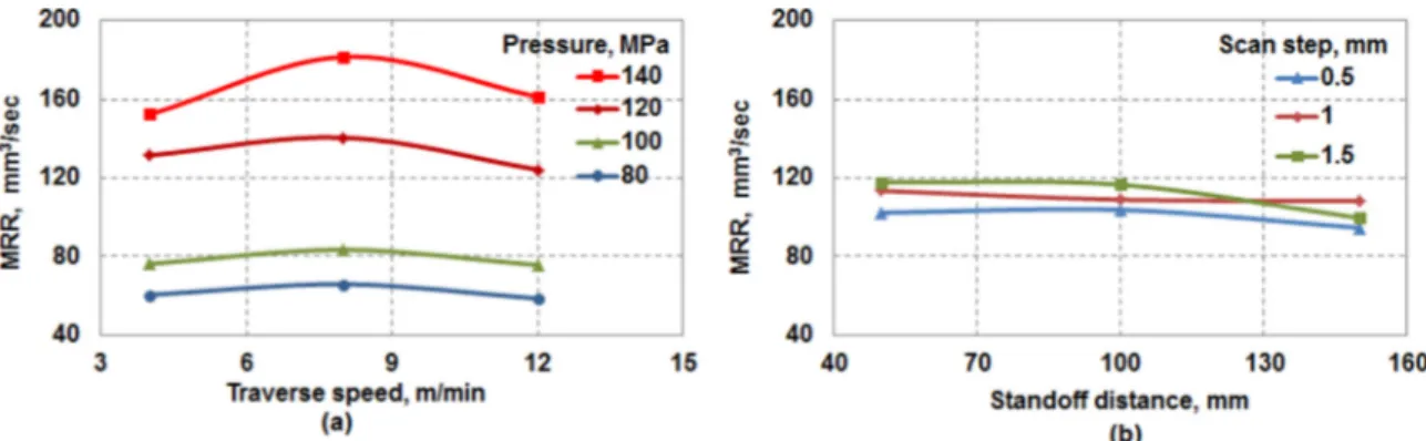
The variations in these results can be explained by the fact that, the material is removed in the form of a channel along the jet traverse path. Scan step determines how close the 2 adjacent channels are, and the geometry of these channels depends on the jet diameter, pressure and traverse speed. If the scan step is smaller than the jet diameter then the two adjacent scanning paths overlap, thereby removing the material at the overlapping zone twice, this implies a higher milled depth. But when the scan step is high, there will be no overlapping of the channels, which accounts for lower milled depth. In addition, when the pressure increases, the kinetic energy of the water and the abrasive parti-cles increase, which in turn increases the impact energy. With the increases of the impact energy, the material removal rate increases too. This can be confirmed by theFig. 4, which depicts the mean effect of the machining parameters on the material removal rate (MRR). It is clear that, when the pressure varies from 80 MPa to 140 MPa, the mean MRR varies from 60 mm3/sec to 150 mm3/sec (for a transverse speed of 4 m/min). It can also be seen that there is critical value of speed for which MRR is the highest for the given set of parameters deviating from it will result in lower MRR (Fig. 4
(a)). However, the rise in the scan step for a standoff distance in-ferior or equal to 100 mm induces a small variation in the MRR. In the case of standoff distance superior to 100 mm a non-negligible
reduction of the MMR is recorded.
3.2. Influence of machining parameters on machined surface quality The mean effect of the machining parameters on the surface quality characteristics viz. average surface roughness (Ra) and root mean square waviness (Wq) along the longitudinal and transverse direction is illustrated in theFigs. 5and6respectively. The surface roughness in the transverse direction of milling is highly influ-enced by the jet pressure and traverse speed (Fig. 5(a)). High pressure increases the energy available to the abrasive particles due to which localized material removal will be vigorous there by creating a rugged surface with high roughness compared to the surface milled with lower pressure. This can be confirmed by SEM observation that broken fibers are found in abundance on the surface milled with high pressure compared to low pressure mil-led surface which is elaborately discussed in later section. Also, influence of scan step on Ra along transverse direction is promi-nent, where increase in scan step contributes to higher surface roughness (Fig. 5(b)). The mean effect of the jet pressure, traverse speed and standoff distance on the surface roughness along the longitudinal direction follows the similar trend as in transverse direction, but the role of scan step is negligible in longitudinal direction.
The mean effect of root mean square surface waviness (Wq) along the transverse and longitudinal direction is highly influ-enced by scan step and standoff distance respectively (Fig. 6). The evolution of surface waviness (Wq) along the transverse direction demonstrates a critical behavior with respect to scan step (Fig. 6
(a)). Here, the waviness decreases to the lower most value when scan step is 1 mm, which is equivalent to the focusing tube dia-meter. This phenomenon suggests that over lapping or separation of scan paths will generate surface waviness. ANOVA acknowl-edges this fact by showing that scan step alone accounts to 52.11% of the total variance for waviness along the transverse direction. It is interesting to note that standoff distance does not play a sig-nificant role in material removal where as it happens to be an important parameter when surface characteristics are considered (Figs. 5(b) and6(b)).
3.3. Scanning electron microscopy and damage
Scanning electron microscope (SEM) imaging done on the milled surface revealed various kinds of damages in the form of craters, ridges, broken fibers and sparing amount of embedded abrasive particles. Craters were the most common damage ob-served across all specimens, however, their magnitude varied with machining parameters (Fig. 7). Inspection of the SEM images af-firmed that the jet pressure and traverse speed were the most influential parameters in deciding the form of the crater whereas
Fig. 3. The mean effect of the machining parameters on the milled depth. With: (a) influence of the pressure & traverse speed and (b) influence of the scan step & standoff distance.
scan step was influential in defining the nature of ridges. Fig. 7
shows SEM images of section of surfaces machined with varying parameters. Presence of broken fibers (Fig. 7(a2), (b3) and (c3)) was wide spread across the milled surface and was common to all types of specimens which is also a vital damage causing a huge impact on the material integrity of the machined component. Specimens milled with high pressure (140 MPa) and high traverse speed (12 m/min) reveals damages inform of fiber-matrix de-bonding and embedded abrasive particles (Fig. 8(b) and (c)). This damage is due to the increased kinetic energy available to the abrasive particles at higher pressure which will in turn increase the impact energy.
The craters were present in 2 different scales which are clas-sified as micro and macro craters. Micro craters (Fig. 7(a3) and (b3)) have a diameter in the range of 50–80 mm and macro craters (Fig. 7(a2) and (b2)) are of diameter in the range of 1–2 mm. Micro
craters are basically formed due to brittle fracture of few fibers due to solid abrasive impact and macro craters are majorly due to the effect of jet pressure and scanning strategy. From the SEM images (Fig. 7(a2) and (b2)) we can see that macro craters appears in specimens milled with pressures equal and superior to 100 MPa and closer standoff distance (50mm) whereas micro craters are present in all specimens. Noticeably, craters placed periodically (Fig. 7(c1)) were found in specimens milled with least scan step (0.5 mm) and least standoff distance (50 mm) and their magnitude increased with increasing pressure. Craters were also found in other specimens but the size was not as significant when compare to high pressure milled specimens and they were randomly dis-tributed. For the same pressure and standoff distance the diameter of macro craters increased with increasing traverse speed which is confirmed from the SEM images inFig. 7(a).
Another interesting correlation was observed between surface Fig. 4. The mean effect of the machining parameters on the material removal rate (MRR). With: (a) Influence of the pressure & traverse speed and (b) Influence of the scan step & standoff distance.
Fig. 5. The mean effect of the machining parameters (a) Pressure & traverse speed on roughness in transverse direction, (b) Scan step & standoff distance on surface roughness in transverse direction.
Fig. 6. The mean effect of machining parameters (a) Scan step & standoff distance on waviness in transverse direction (b) Scan Step & standoff distance with on waviness in longitudinal direction.
parameters and damage. The broken fibers and micro craters contribute to the surface roughness and macro craters contribute to the surface waviness. From the previous section we know that increase in pressure increased surface roughness and also surface waviness significantly (Fig. (5a)).
3.4. 3D topography and x-ray tomography
The topography profiles provide the information on the di-mensions of the damage features observed in SEM images. The
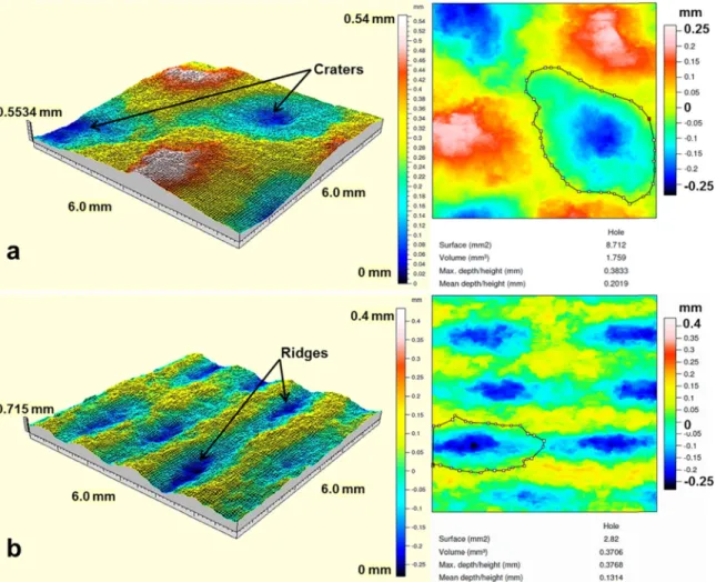
depth, area and volume of the craters calculated gives clear in-dication that their magnitudes were influenced by machining parameters. TheFig. 9shows the topologies of surface machined at jet pressure 120 Mpa, traverse speed 8 mm/min, standoff distance 50 mm with varying scan step. Craters are formed when scan step is 0.5 mm (Fig 9(a)) also ridges and valleys are seen in specimen machined with scan step 1.5 mm (Fig 9(b)) along with the scheme of crater volume measurement. A specific pattern is observed in the crater and ridge formation as seen from both SEM images (Fig. 7(c1)) and topography contours (Fig. 9), this pattern is direct Fig. 7. SEM Images showing the nature of damage observed. Specimens milled at TS – 8 m/min, SO – 50 mm, and SS – 0.5 mm, (a) P – 80 MPa and, showing broken fibers and micro craters, (b) P – 100 MPa showing micro and macro craters, (c) P – 140 MPa showing periodically placed macro craters.
implication of the surface waviness. As discussed previously in section the waviness in transverse direction increases with scan step and pressure whereas in longitudinal direction it increases with pressure which is confirmed from topography analysis. The effect of jet pressure and scan step on the crater volume is shown in Fig. 10, it is very clear that jet pressure increases the crater volume. It is also seen that increase in scan step increases the crater volume however the evolution is random at values of high pressure.
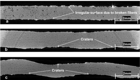
X-ray tomography performed on the AWJ milled specimens did not reveal any underlying internal damages. However this was useful in exactly calculating the load bearing cross sectional area of milled specimens used for tensile tests. Approximation of
rectangular load bearing area would give rise to erroneous tensile strength results with was avoided by using the X-ray tomography images. Fig. 11shows cross sectional X-ray images of machined specimens with best, medium and poor machining quality. The irregular milled surface (Fig. 11(a)) is clearly seen which is due to the presence of micro craters and broken fibers, also the wavy surface which is the outcome of macro craters are seen inFig. 11
(b) and (c).
3.5. Tensile strength
In order to understand the influence of machining quality and damage on the mechanical behavior tensile tests were conducted on the milled specimens. For the sake of comparison 3 specimens with varying machining quality were considered: best, medium and poor quality. The quality was decided based on the surface roughness and crater volume. The machining parameters and average surface properties of the specimens selected for tensile test are shown inTable 2.
The Stress-Strain curves obtained from the tensile tests are il-lustrated inFig. 12. It is clearly noticeable that the specimen with the best machining quality yields the highest tensile strength, which is still inferior to the unmachined specimen tensile strength (2000 MPa). This can be attributed to the fact that the machined surface is full of broken fibers (Fig. 7(a3)) which in actual does not contribute to load carrying capacity. Also from the SEM images (Fig. 7(a2)) we have seen that the machined surface contains nu-merous micro craters which induce discontinuity in the long fibers there by reducing its strength. In the medium quality specimens Fig. 9. Topography of the machined surface and crater volume measurement scheme obtained by optical profilometer system after machining with: P¼120 MPa, TS¼8 mm/ min, SO¼50 mm, (a) SS¼1 mm, (b) SS¼1.5 mm.
Fig. 10. Evolution of total crater volume in the scanned region with respect to jet pressure and scan step.
machined at 100 MPa macro craters start appearing along with broken fibers and micro craters. As discussed in the Sections 3.2and3.3, due to increase in jet pressure there is rise in surface roughness which represents increase in broken fibers and micro craters. These accumulated damages results in a steep 25% de-crease of tensile strength compared to best quality specimen. Further, the specimen with poor machining quality, its tensile strength decreases drastically by 32% compared to specimen with good quality machining which is clearly explainable due to the fact that these specimens machined at 120 MPa have fiber-matrix de-bonding damages along with micro and macro craters. Also, em-bedded abrasive particles act as stress concentration points which further weaken the specimen. Evaluation of tensile modulus re-veals that all the 3 specimens have different tensile modulus va-lues where the specimen with best machining quality has the highest stiffness (126.8 GPa) and the poor machining quality the least (102.7 GPa). This degradation of stiffness suggests the
deteriorating effect of machining quality on mechanical behavior of machined specimens. In all the cases the failure was due to long splitting along the gauge at various locations (Brittle failure with debonding and matrix cracking).
4. Conclusions
This paper presents the experimental study on AWJ milling of unidirectional CFRP composite. The influence of machining para-meters (jet traverse speed, jet pressure, scan step and stand-off distance) on the surface quality and damage is demonstrated. Machining damage in the form of craters was quantified by cal-culating the volume of the craters which was a novel attempt and proved to be effective. The following critical observations can be drawn:
Fig. 11. X-Ray tomography images showing load bearing cross section of specimens with varying machining quality, (a) Best, (b) Medium and (c) Poor quality. Table 2
Machining parameters and resulting surface roughness and waviness of specimens considered for tensile tests.
Quality Pressure (MPa) Speed (mm/min) Scan step (mm) Standoff(mm) Ra (lm) Wq (lm) Crater volume (mm3)
Best 80 12 1.0 100 6.74 8.3 0.432
Medium 100 12 0.5 50 10.3 17.6 1.152
Poor 120 12 0.5 50 9.8 21.5 2.088
#
The milled depth is strongly influenced by scan step, jet pres-sure and jet traverse speed in the increasing order of sig-nificance. In addition, jet pressure and traverse speed are the crucial factors in the case of material removal rate. Whereas standoff distance is an insignificant parameter for both milled depth and material removal rate.#
The jet pressure is most influential factor for 2D surface roughness (Ra) in both transverse and longitudinal directions. However, traverse speed and scan step are next in the order of significance. Also it is to be noted that scan step has minimal influence in evolution of surface roughness in transverse direction.#
Surface waviness (Wq) in transverse direction is influenced by scan step, jet pressure and standoff distance in the order of significance and jet traverse speed is insignificant. It should be noted that surface waviness along transverse direction has the least value for scan step of 1 mm which is close to the focusing tube diameter (1.016 mm). In longitudinal direction the order of significant factors is jet pressure and standoff distance. How-ever, Wq along the longitudinal direction reaches high value at medium traverse speed (8 m/min). It should be noted that waviness is the outcome of periodic pattern of crater formation. Hence, jet pressure, scan step and standoff distance are factors aiding the crater formation.#
Craters (micro and macro) and broken fibers were the most significant form of damage. For the first time, the damage in the form of crater associated with the broken fibers was quantified by introducing crater volume measurement. It was found that the crater volume increases with increase in jet pressure and scan step.#
The behavior of machined specimens under tensile loading have shown that, with best machining quality exhibits highest tensile strength however, it is around 30% less than the strength of the UD ply recommended by the manufactured of composite (Hexcel Composite). Further, tensile strength drastically reduces with reducing quality, which is due the increasing presence of craters.#
The difference in surface roughness of medium and poor quality specimens is negligible, however the difference in their tensile strength is huge, this shows that extent of damage plays an important role in mechanical behavior prediction rather than the surface roughness.References
[1]J.Y. Sheikh-Ahmad, Machining of Polymer Composites, Springer, New York, 2009.
[2]R. Komunduri, Machining of fiber reinforced composites, Mach. Sci. Technol. 1 (1) (1997) 113–152.
[3]R. Teti, Machining of composite materials, CIRP Ann.-Manuf. Technol. 51 (2) (2002) 611–634.
[4]K.B. Katnam, L.F.M. Da Silva, T.M. Young, Bonded repair of composite aircraft structures: a review of scientific challenges and opportunities, Progress. Aerosp. Sci. 61 (2013) 26–42.
[5]F. Collombet, Y.-H. Grunevald, L. Crouzeix, B. Douchin, R. Zitoune, Y. Davila, A. Cerisier, R. Thévenin, Advances in Composites Manufacturing and Process
Design, Elsevier Ltd 2015, pp. 197–227 (Chap. 10).
[6]M. Haddad, R. Zitoune, F. Eyma, B. Castanié, Study of the surface defects and dust generated during trimming of CFRP: influence of tool geometry, ma-chining parameters and cutting speed range, Compos. - Part A: Appl. Sci. Manuf. 66 (2014) 142–154.
[7]A. Hejjaji, D. Singh, S. Kubher, D. Kalyanasundaram, S. Gururaja, Machining damage in FRPs: laser versus conventional drilling, Compos.: Part A 82 (2016) 42–52.
[8]M. Haddad, R. Zitoune, H. Bougherara, F. Eyma, B. Castanié, Study of trimming damages of CFRP structures in function of the machining processes and their impact on the mechanical behavior, Compos. Part B: Eng. 57 (2014) 136–143. [9]J. Paulo Davim, Pedro Reis, Damage and dimensional precision on milling
carbon fiber- reinforced plastics using design experiments, J. Mater. Process. Technol. 160 (2005) 160–167.
[10]M. Ramulu, D. Arola, The influence of abrasive water jet cutting conditions on the surface quality of graphite/epoxy laminates, Int. J. Mach. Tools Manuf. 34 (3) (1994) 295–313.
[11] Jun Wang, A machinability study of polymer matrix composites using abrasive water jet cutting technology, J. Mater. Process. Technol. 94 (1999) 30–35. [12]J.H. Olsen, Cutting with Water Jet, Flow Systems, Kent, USA, 1980. [13] M. Ramulu, K. Colligan. Edge Finishing and Delamination Effects Induced
during Abrasive Water Jet Machining on the Compression Strength of a Gra-phite/epoxy Composite, in: Proceedings of the ASME International Mechanical Engineering Congress and Exposition, Florida, 2005.
[14]S. Paul, A.M. Hoogstrate, C.A. van Luttervelt, H.J.J. Kals, An experimental in-vestigation of rectangular pocket milling with abrasive water jet, J. Mater. Process. Technol. 73 (1998) 179–188.
[15]G. Fowler, P.H. Shipway, I.R. Pashby, A technical note on grit embedment fol-lowing abrasive water-jet milling of a titanium alloy, J. Mater. Process. Technol. 159 (2005) 356–368.
[16] M. Hashish, Controlled-Depth Milling of Isogrid Structures with AWJs Journal of Manufacturing Science and Engineering, vol. 120(1), 1998, pp. 21–27. [17] F. Cenac, Usinage non débouchant par jet d'eau abrasif de matériaux
compo-sites (Ph.D. thesis), Université Paul Sabatier (Toulouse III), 2011.
[18]M. Hashish, An investigation of milling with abrasive-waterjets, J. Eng. Ind. 111 (2) (1989) 158–166.
[19]D.S. Srinivasu, D.A. Axinte, Surface integrity analysis of plain water jet milled advanced engineering composite materials, Procedia CIRP 13 (2014) 371–376. [20] G.L. Sheldon, I. Finnie, The mechanism of material removal in the erosive
cutting of brittle materials, ASME J. Eng. Ind. 88 (4) (1996) 393–400. [21]D. Arola, Mechanisms of material removal in abrasive water jet machining of
common aerospace materials, in: M. Hashish (Ed.), Proc. 7th Amer. Water Jet Conf., 1, Water Jet Techn. Ass., St. Louis, 1993, pp. 43–64.
[22] D. Arola, M. Ramulu, A study of kerf characteristics in abrasive water jet machining of graphite/epoxy composite, J. Eng. Mater. Technol. 118 (1996) 256–265.
[23] M. Ramulu, D. Arola, Water jet and abrasive water jet cutting of undirected graphite/epoxy composite, Composites 24 (1993) 299–308.
[24] M. Haddad, R. Zitoune, F. Eyma, B. Castanié, Influence of machining process and machining induced surface roughness on mechanical properties of con-tinuous fiber composites, Exp. Mech. 55 (2015) 519–528.
[25] D. Arola, M. Ramulu, Machining induced surface texture effects on the flexural properties of graphite/epoxy laminates, Composites 25 (8) (1994) 822–834. [26] D. Arola, M. Ramulu, Net shape manufacturing and the performance of
poly-mer composites under dynamic loads, Exp. Mech. 37 (4) (1997) 379–385. [27] D. Arola, M. Ramulu, Net-shape machining and the process-dependent failure
of fiber-reinforced plastics under static loads, J. Compos., Technol. Res. 20 (4) (1998) 210–220.
[28] Dirk Herzog, Peter Jaeschke, Oliver Meier, Heinz Haferkamp. Investigations on the thermal effect caused by laser cutting with respect to static strength of CFRP International Journal of Machine Tools and Manufacture, vol. 48, 2008, pp. 1464–1473.
[29] P. Ghidossi, M. El Mansori, Pierron Fabrice. Edge machining effects on the failure of polymer matrix composite coupons, Compos.: Part A 35 (7/8) (2004) 989–999.
[30] C.A. Squires, et al., Understanding the factors affecting the compressive testing of unidirectional carbon fibre composites, Compos. Part B 38 (4) (2006) 481–487.
[31]P.H. Shipway, G. Fowler, I.R. Pashby, Characteristics of the surface of a titanium alloy following milling with abrasive waterjets, Wear 258 (2005) 123–132.